EP2990206A1 - Tête d'éjection de liquide et appareil d'éjection de liquide - Google Patents
Tête d'éjection de liquide et appareil d'éjection de liquide Download PDFInfo
- Publication number
- EP2990206A1 EP2990206A1 EP15182385.3A EP15182385A EP2990206A1 EP 2990206 A1 EP2990206 A1 EP 2990206A1 EP 15182385 A EP15182385 A EP 15182385A EP 2990206 A1 EP2990206 A1 EP 2990206A1
- Authority
- EP
- European Patent Office
- Prior art keywords
- space
- vibration
- unit
- liquid ejecting
- pressure chamber
- Prior art date
- Legal status (The legal status is an assumption and is not a legal conclusion. Google has not performed a legal analysis and makes no representation as to the accuracy of the status listed.)
- Granted
Links
- 239000007788 liquid Substances 0.000 title claims abstract description 77
- 239000000758 substrate Substances 0.000 claims abstract description 36
- 238000004891 communication Methods 0.000 claims description 61
- 229910052751 metal Inorganic materials 0.000 claims description 52
- 239000002184 metal Substances 0.000 claims description 52
- 230000004308 accommodation Effects 0.000 claims description 9
- 239000010410 layer Substances 0.000 description 60
- 230000008901 benefit Effects 0.000 description 16
- 238000007639 printing Methods 0.000 description 14
- 239000012790 adhesive layer Substances 0.000 description 12
- 239000011241 protective layer Substances 0.000 description 12
- 239000000463 material Substances 0.000 description 9
- 230000004048 modification Effects 0.000 description 9
- 238000012986 modification Methods 0.000 description 9
- 230000000694 effects Effects 0.000 description 8
- 239000000853 adhesive Substances 0.000 description 7
- 230000001070 adhesive effect Effects 0.000 description 7
- 230000008859 change Effects 0.000 description 7
- 238000004519 manufacturing process Methods 0.000 description 7
- 238000005516 engineering process Methods 0.000 description 5
- 238000005304 joining Methods 0.000 description 5
- 238000003860 storage Methods 0.000 description 5
- 238000010586 diagram Methods 0.000 description 4
- XUIMIQQOPSSXEZ-UHFFFAOYSA-N Silicon Chemical compound [Si] XUIMIQQOPSSXEZ-UHFFFAOYSA-N 0.000 description 3
- 230000000052 comparative effect Effects 0.000 description 3
- 229910052710 silicon Inorganic materials 0.000 description 3
- 239000010703 silicon Substances 0.000 description 3
- 230000007723 transport mechanism Effects 0.000 description 3
- 239000004020 conductor Substances 0.000 description 2
- 239000013078 crystal Substances 0.000 description 2
- 239000010931 gold Substances 0.000 description 2
- 238000000465 moulding Methods 0.000 description 2
- 229910001120 nichrome Inorganic materials 0.000 description 2
- TWNQGVIAIRXVLR-UHFFFAOYSA-N oxo(oxoalumanyloxy)alumane Chemical compound O=[Al]O[Al]=O TWNQGVIAIRXVLR-UHFFFAOYSA-N 0.000 description 2
- 238000005192 partition Methods 0.000 description 2
- 230000002093 peripheral effect Effects 0.000 description 2
- 239000011347 resin Substances 0.000 description 2
- 229920005989 resin Polymers 0.000 description 2
- 239000004065 semiconductor Substances 0.000 description 2
- 230000032258 transport Effects 0.000 description 2
- 239000004593 Epoxy Substances 0.000 description 1
- 239000004642 Polyimide Substances 0.000 description 1
- VYPSYNLAJGMNEJ-UHFFFAOYSA-N Silicium dioxide Chemical compound O=[Si]=O VYPSYNLAJGMNEJ-UHFFFAOYSA-N 0.000 description 1
- 229910045601 alloy Inorganic materials 0.000 description 1
- 239000000956 alloy Substances 0.000 description 1
- 238000003491 array Methods 0.000 description 1
- 230000015572 biosynthetic process Effects 0.000 description 1
- 230000000903 blocking effect Effects 0.000 description 1
- 230000008094 contradictory effect Effects 0.000 description 1
- 238000006073 displacement reaction Methods 0.000 description 1
- 239000013013 elastic material Substances 0.000 description 1
- 238000005530 etching Methods 0.000 description 1
- PCHJSUWPFVWCPO-UHFFFAOYSA-N gold Chemical compound [Au] PCHJSUWPFVWCPO-UHFFFAOYSA-N 0.000 description 1
- 229910052737 gold Inorganic materials 0.000 description 1
- 229910010272 inorganic material Inorganic materials 0.000 description 1
- 239000011147 inorganic material Substances 0.000 description 1
- 239000011810 insulating material Substances 0.000 description 1
- 239000004973 liquid crystal related substance Substances 0.000 description 1
- 238000000034 method Methods 0.000 description 1
- 239000011368 organic material Substances 0.000 description 1
- RVTZCBVAJQQJTK-UHFFFAOYSA-N oxygen(2-);zirconium(4+) Chemical compound [O-2].[O-2].[Zr+4] RVTZCBVAJQQJTK-UHFFFAOYSA-N 0.000 description 1
- 229920001721 polyimide Polymers 0.000 description 1
- 230000000644 propagated effect Effects 0.000 description 1
- 230000001902 propagating effect Effects 0.000 description 1
- 229910052814 silicon oxide Inorganic materials 0.000 description 1
- 238000004544 sputter deposition Methods 0.000 description 1
- 239000000126 substance Substances 0.000 description 1
- 229910001928 zirconium oxide Inorganic materials 0.000 description 1
Images


Classifications
-
- B—PERFORMING OPERATIONS; TRANSPORTING
- B41—PRINTING; LINING MACHINES; TYPEWRITERS; STAMPS
- B41J—TYPEWRITERS; SELECTIVE PRINTING MECHANISMS, i.e. MECHANISMS PRINTING OTHERWISE THAN FROM A FORME; CORRECTION OF TYPOGRAPHICAL ERRORS
- B41J2/00—Typewriters or selective printing mechanisms characterised by the printing or marking process for which they are designed
- B41J2/005—Typewriters or selective printing mechanisms characterised by the printing or marking process for which they are designed characterised by bringing liquid or particles selectively into contact with a printing material
- B41J2/01—Ink jet
- B41J2/135—Nozzles
- B41J2/14—Structure thereof only for on-demand ink jet heads
- B41J2/14201—Structure of print heads with piezoelectric elements
- B41J2/14233—Structure of print heads with piezoelectric elements of film type, deformed by bending and disposed on a diaphragm
- B41J2002/14241—Structure of print heads with piezoelectric elements of film type, deformed by bending and disposed on a diaphragm having a cover around the piezoelectric thin film element
-
- B—PERFORMING OPERATIONS; TRANSPORTING
- B41—PRINTING; LINING MACHINES; TYPEWRITERS; STAMPS
- B41J—TYPEWRITERS; SELECTIVE PRINTING MECHANISMS, i.e. MECHANISMS PRINTING OTHERWISE THAN FROM A FORME; CORRECTION OF TYPOGRAPHICAL ERRORS
- B41J2202/00—Embodiments of or processes related to ink-jet or thermal heads
- B41J2202/01—Embodiments of or processes related to ink-jet heads
- B41J2202/11—Embodiments of or processes related to ink-jet heads characterised by specific geometrical characteristics
Definitions
- the present invention relates to a technology of ejecting a liquid such as an ink.
- the first pressurized liquid chamber and the second pressurized liquid chamber are controlled into flow path properties which are the same to each other, by the configuration that positions and shapes of narrowing units which apply flow path resistance to the ink by being formed on a downstream side of the common liquid chamber in the first pressurized liquid chamber and the second pressurized liquid chamber are different from each other.
- An advantage of some aspects of the invention is to control flow path properties of a pressure chamber by a simple configuration.
- a liquid ejecting head including: a pressure chamber substrate where a plurality of spaces to be a pressure chamber along a first direction are formed in a second direction which is perpendicular to the first direction; a vibration plate that seals the space by being stacked in the pressure chamber substrate; and a piezoelectric element and a vibration restraint unit that are stacked in the vibration plate on an opposite side to the pressure chamber substrate, wherein positions at one end in the first direction are different from each other in a first space and a second space among the plurality of spaces, and the vibration restraint unit suppresses a vibration of the vibration plate by being formed so as to overlap with at least the one end side portion in the first space in a planar view.
- the vibration restraint unit is stacked in the vibration plate so as to overlap with at least the one end side portion in the first space in the planar view, the vibration (capacity change of the pressure chamber) of the portion correlating with the one end of the first space among the vibration plate is suppressed. Therefore, there is an advantage that the flow path properties (for example, excluded volume) of the pressure chamber can be controlled by the simple configuration, in comparison with the configuration of JP-A-2011-140173 of controlling the flow path properties of each pressurized liquid chamber by making the positions of the narrowing units be different from each other within the flow path.
- the vibration restraint unit overlaps with the one end side portion in the first space, and does not overlap with the second space in the planar view. Moreover, in a second aspect, the vibration restraint unit overlaps with the one end side portion in both of the first space and the second space in the planar view.
- an excluded volume is preferably aligned by the vibration restraint unit, in the first space and the second space.
- the excluded volume of the first space and the excluded volume of the second space can be equalized by the simple configuration of suppressing the vibration due to the vibration restraint unit.
- the excluded volume means a change amount (capacity change amount) of the volume of the pressure chamber by the vibration of the vibration plate.
- positions at the other end in the first direction are preferably the same to each other, in the first space and the second space.
- the positions at the other end in the first direction are common in the first space and the second space, there is the advantage that the structure of the flow path for supplying the liquid to each space is simplified.
- the capacities are different from each other by making the positions at the one end be different from each other in the first space and the second space, but as described above, the excluded volumes can be equalized in the first space and the second space, by the simple configuration of suppressing the vibration due to the vibration restraint unit.
- the piezoelectric element includes an upper electrode, a piezoelectric body layer, and a lower electrode
- the vibration restraint unit includes a metal layer which is stacked in the upper electrode.
- the vibration restraint unit includes a protection member that has an accommodation place where the piezoelectric element is displaceable on an inside, and is stacked in the vibration plate so as to cover the piezoelectric element.
- the protection member which protects the piezoelectric element is used as a vibration restraint unit, there is the advantage that the configuration of the liquid ejecting head is simplified, in comparison with the case where the element which is dedicated to suppressing the vibration of the vibration plate is used as a vibration restraint unit.
- the liquid ejecting head preferably further includes: a communication plate that is stacked in the pressure chamber substrate on an opposite side to the vibration plate, and has a communication hole communicating with the space and a nozzle on the one end side, wherein a flow path diameter of the communication hole is greater than the space in the second direction, and one end of the communication hole is positioned on an outside of the space in the first direction.
- a communication plate that is stacked in the pressure chamber substrate on an opposite side to the vibration plate, and has a communication hole communicating with the space and a nozzle on the one end side, wherein a flow path diameter of the communication hole is greater than the space in the second direction, and one end of the communication hole is positioned on an outside of the space in the first direction.
- a liquid ejecting apparatus includes the liquid ejecting head according to each aspect described above.
- a good example of the liquid ejecting head is the printing apparatus of ejecting the ink, but usefulness of the liquid ejecting apparatus according to the aspect of the invention is not limited to the printing.
- Fig. 1 is a partial configuration diagram of an ink jet type printing apparatus 10 according to a first embodiment of the invention.
- the printing apparatus 10 of the first embodiment is a liquid ejecting apparatus of ejecting an ink being an example of a liquid onto a medium (ejecting target) 12 such as printing paper, and includes a control apparatus 22, a transport mechanism 24, and a liquid ejecting module 26.
- a liquid container (cartridge) 14 accommodating the ink is mounted on the printing apparatus 10.
- the control apparatus 22 controls overall the respective elements of the printing apparatus 10.
- the transport mechanism 24 transports the medium 12 in a Y direction, based on the control by the control apparatus 22.
- the liquid ejecting module 26 includes a plurality of liquid ejecting heads 100.
- the liquid ejecting module 26 of the first embodiment is a line head where the plurality of liquid ejecting heads 100 are arrayed (so-called zigzag arrangement or so-called staggered arrangement) along an X direction intersecting with (which is typically orthogonal to) the Y direction.
- Each liquid ejecting head 100 ejects the ink which is supplied from the liquid container 14 onto the medium 12, based on the control by the control apparatus 22.
- Each liquid ejecting head 100 forms a desired image on a surface of the medium 12 by ejecting the ink onto the medium 12 in parallel with the transport of the medium 12 by the transport mechanism 24.
- a direction that is perpendicular to an X-Y plane (plane which is parallel to the surface of the medium 12) is designated as a Z direction.
- An ejecting direction (downward side of a vertical direction) of the ink by each liquid ejecting head 100 correlates with the Z direction.
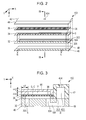
- Fig. 2 is an exploded perspective view of any one of the liquid ejecting heads 100.
- Fig. 3 is a sectional (section which is parallel to a Y-Z plane) view taken along III-III line in Fig. 2 .
- the liquid ejecting head 100 of the first embodiment is a structure where a pressure chamber substrate 34, a vibration plate 36, a case 42, and a protection member 44 are installed on a negative side plane of the Z direction of a communication plate 32, and a nozzle plate 46 and a compliance unit 48 are installed on a positive side plane of the Z direction of the communication plate 32.
- the respective elements of the liquid ejecting head 100 are almost flat plate-shaped members which are schematically long in the X direction, and are joined to each other, for example, by using an adhesive.
- Fig. 4 is a plan view of the nozzle plate 46 when seen from the negative side (communication plate 32 side) of the Z direction.
- the nozzle plate 46 of the first embodiment is a flat plate where a plurality of nozzles (ejecting holes) N are formed, and is fixed on the surface of the positive side of the Z direction of the communication plate 32, for example, by using the adhesive.
- the plurality of nozzles N are arrayed along the X direction.
- the plurality of nozzles N of the first embodiment are divided into a first nozzle array G1 and a second nozzle array G2 which are arrayed in parallel at intervals to each other in the Y direction.
- the first nozzle array G1 is positioned on the positive side of the Y direction with respect to the second nozzle array G2.
- Each of the first nozzle array G1 and the second nozzle array G2 is a set of the plurality of nozzles N which are arrayed by a predetermined pitch p along the X direction. Positions of the respective nozzles N in the X direction are different from each other in the first nozzle array G1 and the second nozzle array G2. Specifically, the respective nozzles N of the second nozzle array G2 are positioned in the middle of the respective nozzles N of the first nozzle array G1 which are adjacent to each other in the X direction. That is, the plurality of nozzles N are arrayed (so-called staggered arrangement) into a zigzag shape along the X direction.
- Fig. 5 is a plan view of the pressure chamber substrate 34.
- the pressure chamber substrate 34 of the first embodiment is a flat plate where a plurality of spaces S (S1, S2) to be a pressure chamber (cavity) are formed.
- the plurality of spaces S are arrayed along the X direction (second direction) so as to correlate with the respective nozzles N.
- Each of the plurality of spaces S is a through hole along the Y direction (first direction) in a planar view.
- each space S is formed into a long shape which is extended along the Y direction in the planar view, throughout one end (referred to as "first end”, hereinafter) EA of the positive side of the Y direction and the other end (referred to as “second end”, hereinafter) EB of the negative side.
- first end hereinafter
- second end hereinafter
- a material and a manufacturing method of the pressure chamber substrate 34 are arbitrary, for example, by selectively removing a substrate which is formed of a silicon single crystal due to a semiconductor manufacturing technology such as an etching, it is possible to form the pressure chamber substrate 34 of the intended shape simply and highly accurately.
- the plurality of spaces S which are formed in the pressure chamber substrate 34 are divided into a plurality of first spaces S1 and a plurality of second spaces S2.
- the first space S1 and the second space S2 are alternately arrayed along the X direction. If being focused on a portion (referred to as "end unit”, hereinafter) P which is positioned on the first end EA side among each space S in the planar view, the end unit P of the first space S1 overlaps with one nozzle N of the first nozzle array G1 in the planar view, and the end unit P of the second space S2 overlaps with one nozzle N of the second nozzle array G2 in the planar view.
- end unit P of the first space S1 overlaps with one nozzle N of the first nozzle array G1 in the planar view
- the end unit P of the second space S2 overlaps with one nozzle N of the second nozzle array G2 in the planar view.
- the first end EA of the first space S1 is positioned on the positive side in the Y direction in comparison with the first end EA of the second space S2. That is, the positions at the first end EA in the Y direction are different from each other in the first space S1 and the second space S2.
- the positions at the second end EB in the Y direction are common in the first space S1 and the second space S2. That is, as illustrated in Fig. 5 , the second end EB of each first space S1 and the second end EB of each second space S2 are positioned on a straight line which is parallel to the X direction.
- the full lengths (distances between the first end EA and the second end EB) of the first space S1 and the second space S2 are different from each other in the Y direction. Furthermore, a flow path diameter (width) ⁇ A of each space S in the X direction is the same in the first space S1 and the second space S2.
- the communication plate 32 of Fig. 2 is a flat plate for forming a flow path.
- an opening unit 322 a plurality of supply holes 324, and a plurality of communication holes 326 are formed in the communication plate 32 of the first embodiment.
- the opening unit 322 is a through hole which is formed into a long shape along the X direction in the planar view, so as to continue throughout the plurality of nozzles N.
- each of the plurality of supply holes 324 and communication holes 326 are through holes which are individually formed per a respective one of the plurality of the nozzles N.
- a groove-shaped branch path (manifold) 328 which is extended in Y direction is formed per the supply hole 324 on the surface of the positive side (opposite side to the pressure chamber substrate 34) of the Z direction among the communication plate 32, so as to communicate with the supply hole 324 and the opening unit 322.
- Figure 3 illustrates for simplicity a single groove-shaped branch path 328 and supply hole 324 but it is to be understood that one such groove-shaped branch path 328 is provided for each of the plurality of supply holes 324, in the manner shown in Figure 3 .
- the material and the manufacturing method of the communication plate 32 are arbitrary, for example, in the same manner as the pressure chamber substrate 34 as described above, by selectively removing a substrate which is formed of the silicon single crystal due to the semiconductor manufacturing technology, it is possible to form the communication plate 32 of the intended shape simply and highly accurately.
- each supply hole 324 of the communication plate 32 is formed per the space S, so as to overlap with a region of the second end EB side among the respective spaces S (S1, S2) of the pressure chamber substrate 34 in the planar view.
- the plurality of supply holes 324 of the communication plate 32 are arrayed into a straight line shape along the X direction.
- the flow path of the ink which branches off into each branch path 328 from the opening unit 322 of the communication plate 32 and reaches the space S through the supply hole 324 of a downstream side is individually formed per the nozzle N.
- each communication hole 326 is formed per the space S, so as to overlap with the end unit P of the first end EA side among the respective spaces S (S1, S2) of the pressure chamber substrate 34 in the planar view. Therefore, the respective spaces S of the pressure chamber substrate 34 communicate with the nozzle N through the communication hole 326.
- the first space S1 communicates with the nozzles N of the first nozzle array G1 through the communication hole 326
- the second space S2 communicates with the nozzle N of the second nozzle array G2 through the communication hole 326.
- each communication hole 326 correlating with the first space S1 is positioned on the positive side of the Y direction with respect to each communication hole 326 correlating with the second space S2. That is, the plurality of communication holes 326 are arrayed (zigzag arrangement or staggered arrangement) into two arrays correlating with the first space S1 and the second space S2 along the X direction.
- a flow path diameter ⁇ B of the communication hole 326 in the X direction is greater than the flow path diameter ⁇ A of the space S in the X direction ( ⁇ B > ⁇ A).
- one end of the positive side of the Y direction among the communication hole 326 is positioned on an outside of each space S in the planar view. That is, a margin (inner wall plane) of the positive side of the Y direction among the communication hole 326 is positioned on the positive side of the Y direction when seen from the first end EA of the space S correlating with the communication hole 326.
- the flow path that reaches the nozzle N through the communication hole 326 of which the flow path diameter is enlarged in comparison with the space S is formed on the downstream side of the space S. Therefore, the flow path resistance on the downstream side of the space S is reduced, in comparison with the configuration that the flow path diameter ⁇ B of the communication hole 326 is less than the flow path diameter ⁇ A of the space S, and the ink within the space S may smoothly flow into the nozzle N.
- the case 42 is installed on the surface of the negative side of the Z direction of the communication plate 32.
- the case 42 is a structure which is integrally molded by an ejection molding of a resin material.
- an accommodation unit 422 and an introduction hole 424 are formed in the case 42 of the first embodiment.
- the accommodation unit 422 is a concave unit having an outer shape correlating with the opening unit 322 of the communication plate 32 in the planar view
- the introduction hole 424 is a through hole communicating with the accommodation unit 422.
- the opening unit 322 of the communication plate 32 and the accommodation unit 422 of the case 42 communicate with each other, and the space functions as a liquid storage chamber (reservoir) R.
- the ink passing through the introduction hole 424 which is supplied from the liquid container 14, is stored in the liquid storage chamber R.
- the compliance unit 48 of Fig. 2 and Fig. 3 is an element for absorbing a pressure change of the liquid storage chamber R, and includes, for example, a flexible sheet member.
- the compliance unit 48 is installed on the surface of the positive side of the Z direction of the communication plate 32, so as to configure a bottom plane of the liquid storage chamber R by blocking the opening unit 322 of the communication plate 32, each branch path 328, and each supply hole 324.
- the vibration plate 36 is stacked on the surface of the side of the pressure chamber substrate 34 opposite to the communication plate 32 . That is, each space S of the pressure chamber substrate 34 is sealed by the vibration plate 36.
- the vibration plate 36 of the first embodiment is a flat plate which is elastically vibratile.
- the vibration plate 36 is configured by stacking an elastic film which is formed of an elastic material such as a silicon oxide, and an insulating film which is formed of an insulating material such as a zirconium oxide.
- the vibration plate 36 and the communication plate 32 are positioned counter to each other by interposing each space S of the pressure chamber substrate 34 therebetween, and thereby, a pressure chamber C of using the vibration plate 36 as an upper plane and the communication plate 32 as a lower plane is formed.
- the ink which is stored in the liquid storage chamber R is parallelly supplied to each pressure chamber C by branching off into the plurality of branch paths 328, and passing through the supply hole 324, and each pressure chamber C is filled with the ink.
- the ink is ejected to the outside by passing through the communication hole 326 and the nozzle N from the pressure chamber C depending on the vibration of the vibration plate 36.
- volume of the pressure chamber C correlating with the first space S1 and the pressure chamber C correlating with the second space S2 are different from each other. Specifically, the volume of the pressure chamber C correlating with the first space S1 is greater than the volume of the pressure chamber C correlating with the second space S2.
- the Y direction position of the communication hole 326 correlating with the first space S1 and the Y direction position of the communication hole 326 correlating with the second space S2 are different from each other. That is, the interval between the respective communication holes 326 is enlarged in comparison with Comparative Example. Therefore, there is an advantage that the above-described problem of propagating the internal pressure change of the communication hole 326 to the adjacent communication hole 326 may be reduced.
- a plurality of piezoelectric elements 38 are formed on the surface of the side of the vibration plate 36 opposite to the pressure chamber substrate 34.
- Fig. 6 is a plan view and a sectional (section taken along VI-VI line) view in a case of enlarging the surface of the side of the vibration plate 36 opposite to the pressure chamber substrate 34.
- a plurality of first electrodes 382, a piezoelectric body layer 384, and a second electrode 386 are stacked on the surface of the side of the vibration plate 36 opposite to the pressure chamber substrate 34.
- Each of the plurality of first electrodes 382 is an individual electrode of the long shape along the Y direction which is individually formed per the space S (per the pressure chamber C) so as to overlap with the space S in the planar view, and is arrayed along the X direction at the intervals to each other.
- the piezoelectric body layer 384 is a film body that covers the plurality of first electrodes 382 by being formed of a piezoelectric material so as to continue throughout the plurality of spaces S.
- the piezoelectric body layer 384 of the first embodiment is formed throughout the positive side position of the Y direction when seen from the first end EA of each space S, and the negative side position of the Y direction when seen from the second end EB of each space S.
- a notch (slit) 385 which is extended along the Y direction, is formed in the position of the interval between the respective first electrodes 382 which are adjacent to each other among the piezoelectric body layer 384 in the planar view.
- the second electrode 386 is a common electrode that covers the plurality of first electrodes 382 and the piezoelectric body layer 384 by being formed so as to continue throughout the plurality of spaces S.
- Each piezoelectric element 38 is displaced depending on a drive signal which is supplied to the first electrode 382 from an external apparatus.
- the pressure of the pressure chamber C is changed by the vibration of the vibration plate 36 which is coupled with the displacement of the piezoelectric element 38, and thereby, the ink filling in the pressure chamber C is ejected to the outside from the nozzle N by passing through the communication hole 326. Since the notch 385 is formed between the respective piezoelectric elements 38 which are adjacent to each other, the propagation of the vibration throughout the piezoelectric elements 38 which are adjacent to each other is suppressed.
- the protection member 44 of Fig. 2 and Fig. 3 is a flat plate-shaped structure for protecting each piezoelectric element 38, and is stacked on the vibration plate 36 by being integrally formed, for example, due to the ejection molding of the resin material.
- the protection member 44 of the first embodiment is fixed to the vibration plate 36 so as to cover the plurality of piezoelectric elements 38, for example, by using the adhesive.
- a space referred to as "accommodation space", hereinafter
- V is formed on the surface of the vibration plate 36 side among the protection member 44.
- the protection member 44 includes a flat plate-shaped covering unit 442 that covers the plurality of piezoelectric elements 38, and a frame-shaped joining unit 444 protruding from the periphery of the covering unit 442 toward the vibration plate 36 side.
- the covering unit 442 is positioned counter to the vibration plate 36 at a predetermined interval. That is, the joining unit 444 of the protection member 44 functions as a leg unit which supports the covering unit 442.
- the accommodating space V of the first embodiment is formed into a rectangular shape that encloses the plurality of piezoelectric elements 38 which are formed on the surface of the vibration plate 36 in the planar view. Each piezoelectric element 38 is displaced depending on the drive signal, in a state of being accommodated in the accommodation space V.
- the joining unit 444 of the protection member 44 includes a portion (referred to as "supporting unit”, hereinafter) 52 which is positioned on the positive side of the Y direction in the planar view and is extended along the X direction.
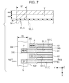
- Fig. 7 is a plan view and a sectional (section taken along VII-VII line) view illustrating a relationship between the supporting unit 52 of the protection member 44 and each space S (each pressure chamber C) of the pressure chamber substrate 34. Furthermore, the illustration of each piezoelectric element 38 is conveniently omitted in Fig. 7 .
- the supporting unit 52 of the first embodiment is arranged so as to overlap with the end unit P of the first end EA side in each first space S1 in the planar view, and not to overlap with the end unit P of each second space S2. That is, the supporting unit 52 is extended along the X direction so as to continue throughout the end units P of the plurality of first spaces S1, and a margin (inner peripheral plane) 522 of the supporting unit 52 is extended into the straight line shape along the X direction between the end unit P of each first space S1 and the end unit P of each second space S2. Furthermore, each notch 385 of the piezoelectric body layer 384 is positioned on the negative side of the Y direction when seen from the margin 522 of the supporting unit 52.
- a region (referred to as "counter region”, hereinafter) A which overlaps with each space S among the vibration plate 36 in the planar view is conveniently illustrated by a mesh in Fig. 7 .
- a counter region A1 is a region which overlaps with the first space S1
- a counter region A2 is a region which overlaps with the second space S2 in Fig. 7 . Since the supporting unit 52 is fixed to the surface of the vibration plate 36, the vibration is suppressed in the region which overlaps with the supporting unit 52 among each counter region A of the vibration plate 36 in the planar view, in comparison with the region which does not overlap with the supporting unit 52 among the counter region A.
- the supporting unit 52 of the protection member 44 overlaps with the end unit P of the first end EA side among the first space S1 as described above, the portion correlating with the end unit P among the counter region A1 correlating with the first space S1 is restrained by the supporting unit 52, and the vibration is suppressed thereat. That is, the vibration of the region which overlaps with the supporting unit 52 is suppressed by the supporting unit 52, and only the region which does not overlap with the supporting unit 52 is vibrated as being coupled with the piezoelectric element 38 in the counter region A1 correlating with the first space S1 among the vibration plate 36, in contrast with the case where the counter region A2 correlating with the second space S2 is vibrated throughout the whole region as being coupled with the piezoelectric element 38.
- the partial region which is defined by the supporting unit 52 selectively functions as a vibration region in the counter region A1, in contrast with the case where the whole of the counter region A2 functions as a vibration region (region which is actually vibrated).
- the capacity of the first space S1 is greater than the capacity of the second space S2 as described above, but the vibration of the counter region A1 among the vibration plate 36 is partially suppressed by the supporting unit 52 of the protection member 44, and thereby, a change amount (excluded volume) of the volume of the pressure chamber C by the vibration of the vibration plate 36, is adjusted to be almost the same in the first space S1 and the second space S2.
- the supporting unit 52 of the protection member 44 is stacked on the vibration plate 36 so as to overlap with the end unit P of the first end EA side of the first space S1 in the planar view, and thereby, the vibration of the counter region A1 is partially suppressed among the vibration plate 36. Therefore, there is the advantage that the flow path properties (for example, the excluded volume described above) of each pressure chamber C may be suppressed by the simple configuration, in comparison with the technology of JP-A-2011-140173 of adjusting the flow path properties of each pressurized liquid chamber by making the positions of the narrowing units be different from each other within the flow path.
- the positions at the second end EB are common in each of the first space S1 and the second space S2. That is, the second end EB of each first space S1 and the second end EB of each second space S2 are positioned on the straight line which is parallel to the X direction. Therefore, there is the advantage that the structure of the flow path for supplying the ink to each space S may be simplified, in comparison with the configuration of making the positions at the second end EB be different from each other in the first space S1 and the second space S2.
- the plurality of supply holes 324 of the communication plate 32 may be arrayed into the straight line shape in the X direction, and the full lengths of the plurality of branch paths 328 may be the same. Still more, for example, there is the advantage that a bubble which is mixed into the ink is easily discharged to the outside, by simplify the structure of the flow path.
- the positions at the first end EA are different from each other in the first space S1 and the second space S2 on the basis of the configuration that the positions at the second end EB are common in the first space S1 and the second space S2 as described above, since a difference between the volumes of the first space S1 and the second space S2 becomes apparent, the difference between the flow path properties of the first space S1 and the second space S2 may be particularly a problem.
- the protection member 44 for protecting the piezoelectric element 38 is used as a unit (vibration restraint unit) that suppresses the vibration of the vibration plate 36. Therefore, there is the advantage that the configuration of the liquid ejecting head 100 is simplified (for example, the number of components is reduced), in comparison with the case of installing an element which is dedicated to suppressing the vibration of the vibration plate 36.
- Fig. 8 is a plan view and a sectional (section taken along VIII-VIII line) view illustrating a relationship between the supporting unit 52 of the protection member 44 and each space S of the pressure chamber substrate 34 in the second embodiment.
- the supporting unit 52 of the protecting member 44 of the second embodiment is arranged so as to overlap with the end unit P of the first end EA side in both of the first space S1 and the second space S2 in the planar view. That is, the margin 522 of the supporting unit 52 is extended into the straight line shape along the X direction in the negative side position of the Y direction when seen from each end unit P of the first space S1 and the second space S2.
- an area of the region which overlaps with the supporting unit 52 among the first space S1 in the planar view is greater than an area of the region which overlaps with the supporting unit 52 among the second space S2.
- the vibration of the portion including the end unit P of the first end EA side is also suppressed by the supporting unit 52 in the counter region A2 correlating with the second space S2, in addition to that the vibration of the portion including the end unit P among the counter region A1 correlating with the first space S1 is suppressed by the supporting unit 52 in the same manner as the first embodiment. That is, the vibration region is defined by the supporting unit 52 in both of the counter region A1 and the counter region A2.
- the same effects as the first embodiment are realized.
- the supporting unit 52 is repeated in both of the first space S1 and the second space S2, it is possible to make conditions of the vibration of the vibration plate 36 be similar to each other in the first space S1 and the second space S2, in comparison with the first embodiment where the counter region A2 is not influenced by the supporting unit 52 while the vibration of the counter region A1 is suppressed by the supporting unit 52. Therefore, there is the advantage that each pressure chamber C is highly accurately controlled into the same flow path properties (for example, the excluded volume), in comparison with the first embodiment.
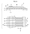
- Fig. 9 is a plan view and a sectional (section taken along IX-IX line) view which are obtained by enlarging the surface of the vibration plate 36 in a third embodiment.
- a metal layer 54 is formed on the plane of the vibration plate 36.
- the metal layer 54 is a conductive film that is stacked on the second electrode 386.
- the metal layer 54 is extended into the straight line shape (belt shape) along the X direction so as to cover the periphery of the positive side of the Y direction among the second electrode 386.
- the material of the metal layer 54 is arbitrary, for example, a single substance metal such as gold (Au) or nichrome (NiCr), or an alloy containing such the metal is suitably adopted as a material of the metal layer 54.
- the manufacturing method of the metal layer 54 is arbitrary, for example, it is possible to form the metal layer 54 into a film thickness of 50 nm or more by a known film forming method such as a sputtering. Since the metal layer 54 is stacked on the second electrode 386 in the third embodiment as described above, the influence of the resistance of the second electrode 386 is reduced. From a viewpoint of realizing the above effects, the configuration of forming the metal layer 54 by the conductive material of the low resistance in comparison with the second electrode 386 is suitable.
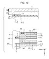
- Fig. 10 is a plan view and a sectional (section taken along X-X line) view illustrating a relationship between the metal layer 54 and each space S in the third embodiment.
- the metal layer 54 of the third embodiment is formed so as to overlap with the end unit P of the first end EA side in each first space S1 in the planar view, and not to overlap with the end unit P of each second space S2, in the same manner as the supporting unit 52 of the first embodiment. That is, a margin 542 on the negative side of the Y direction among the metal layer 54 is extended into the straight line shape along the X direction between the end unit P of each first space S1 and the end unit P of each second space S2.
- the supporting unit 52 of the protection member 44 of the third embodiment does not overlap with any of the first space S1 and the second space S2 in the planar view. That is, the margin 522 of the supporting unit 52 is positioned on the positive side of the Y direction when seen from each first end EA of the first space S1 and the second space S2.
- the metal layer 54 since the metal layer 54 overlaps with the end unit P of the first space S1, the portion correlating with the end unit P among the counter region A1 correlating with the first space S1 is restrained by the metal layer 54, and thereby, the vibration is suppressed. That is, the metal layer 54 functions as a sinker (deadweight) for suppressing the vibration of the counter region A1.
- the partial region which is defined by the metal layer 54 selectively functions as a vibration region in the counter region A1 correlating with the first space S1, in contrast with the case where the whole of the counter region A2 functions as a vibration region, in the same manner as the first embodiment. Therefore, the same effects as the first embodiment are also realized in the third embodiment.
- there is no need of using the protection member 44 for suppressing the vibration of the vibration plate 36 in the third embodiment there is the advantage that the freedom degrees of the shape and the dimension of the protection member 44 are increased in comparison with the first embodiment.
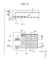
- the liquid ejecting head 100 of a fourth embodiment includes the metal layer 54 which is stacked on the second electrode 386, in the same manner as the third embodiment.
- Fig. 11 is a plan view and a sectional (section take along XI-XI line) view illustrating a relationship between the metal layer 54 and each space S in the fourth embodiment.
- the metal layer 54 of the fourth embodiment is arranged so as to overlap with the end unit P in both of the first space S1 and the second space S2 in the planar view. That is, the margin 542 of the metal layer 54 is extended into the straight line shape along the X direction on the negative side of the Y direction when seen from each end unit P of the first space S1 and the second space S2.
- the area of the region which overlaps with the metal layer 54 among the first space S1 in the planar view is greater than the area of the region which overlaps with the metal layer 54 among the second space S2.
- the vibration of the portion including the end unit P is also suppressed by the metal layer 54 in the counter region A2 correlating with the second space S2, in addition to that the vibration of the portion including the end unit P among the counter region A1 correlating with the first space S1 is suppressed by the metal layer 54 in the same manner as the third embodiment. That is, the vibration region is defined by the metal layer 54 in both of the counter region A1 and the counter region A2.
- the same effects as the third embodiment are realized. Moreover, in the fourth embodiment, since the metal layer 54 is repeated in both of the first space S1 and the second space S2, it is possible to make the conditions of the vibration of the vibration plate 36 be similar to each other in the first space S1 and the second space S2, in the same manner as the second embodiment. Therefore, there is the advantage that each pressure chamber C is highly accurately controlled into the same flow path properties, in comparison with the third embodiment.
- a fifth embodiment is an embodiment in which both of the supporting unit 52 ( Fig. 7 ) of the first embodiment and the metal layer 54 ( Fig. 10 ) of the third embodiment are installed.
- Fig. 12 is a plan view and a sectional (section taken along XII-XII line) view illustrating a relationship between the supporting unit 52, the metal layer 54 and each space S of the pressure chamber substrate 34 in the fifth embodiment.
- both of the supporting unit 52 which configures the protection member 44 and the metal layer 54 which is stacked in the second electrode 386 overlap with the end unit P of the first end EA side among each first space S1 in the planar view. Therefore, the same effects as the first embodiment and the third embodiment are realized therein.
- the vibration of the counter region A1 among the vibration plate 36 may be sufficiently suppressed, in comparison with the first embodiment in which only the supporting unit 52 overlaps with the first space S1, and the third embodiment in which only the metal layer 54 overlaps with the first space S1.
- a sixth embodiment is an embodiment in which both of the supporting unit 52 ( Fig. 8 ) of the second embodiment and the metal layer 54 ( Fig. 11 ) of the fourth embodiment are installed.
- Fig. 13 is a plan view and a sectional (section taken along XIII-XIII line) view illustrating a relationship between the supporting unit 52, the metal layer 54 and each space S of the pressure chamber substrate 34 in the sixth embodiment.
- the supporting unit 52 and the metal layer 54 overlap with the end unit P of the first end EA side among both of the first space S1 and the second space S2 in the planar view. Therefore, the same effects as the second embodiment and the fourth embodiment are realized therein.
- the vibration of the respective counter regions A (A1, A2) among the vibration plate 36 may be sufficiently suppressed, in comparison with the configuration that only one of the supporting unit 52 and the metal layer 54 overlaps with each space S.
- the unit (vibration restraint unit) that suppresses the vibration of the vibration plate 36 is not limited to the supporting unit 52 or the metal layer 54 illustrated in each embodiment described above.
- an element (adhesive layer 56, protective layer 58) illustrated hereinafter may be used as a vibration restraint unit.
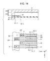
- Fig. 14 an embodiment in which the adhesive layer 56 which is formed by an adhesive used for bonding of each element of the liquid ejecting head 100 is used as a vibration restraint unit is illustrated.
- the adhesive layer 56 of Fig. 14 is used for fixing the protection member 44 to the surface of the vibration plate 36.
- the material of the adhesive layer 56 is arbitrary, for example, the adhesive such as an epoxy-based adhesive or a silicon-based adhesive is suitably used.
- the adhesive layer 56 overlaps with the end unit P of the first end EA side among each first space S1 in the planar view, and the vibration of the region correlating with the end unit P of the first space S1 among the counter region A1 of the vibration plate 36 is suppressed.
- a configuration that the adhesive layer 56 overlaps with the end unit P of the first end EA side in both of the first space S1 and the second space S2, or a configuration that the supporting unit 52 or the metal layer 54 along with the adhesive layer 56 overlaps with one or both of the first space S1 and the second space S2 may be adopted.
- the protective layer 58 for protecting each piezoelectric element 38 is illustrated.
- the protective layer 58 of Fig. 15 is an insulating layer which is stacked on the second electrode 386 so as to overlap with the periphery portion of each piezoelectric element 38 in the planar view.
- the protective layer 58 is formed into the film thickness of 25 nm or more by an organic material such as polyimide, or an inorganic material such as an aluminum oxide (Al 2 O 3 ).
- the protective layer 58 overlaps with the end unit P of the first end EA side among each first space S1 in the planar view, and the vibration of the region correlating with the end unit P of the first space S1 among the counter region A1 of the vibration plate 36 is suppressed.
- a configuration that the protective layer 58 overlaps with the end unit P in both of the first space S1 and the second space S2, or a configuration that the supporting unit 52 or the metal layer 54 along with the protective layer 58 overlaps with the first space S1 or the second space S2 may be adopted.
- the vibration restraint unit is overall expressed as an element which suppresses the partial vibration of the vibration plate 36.
- the supporting unit 52, the metal layer 54, the adhesive layer 56 and the protective layer 58 are examples of the vibration restraint unit.
- a combination of the plurality of elements may be used as a vibration restraint unit.
Landscapes
- Particle Formation And Scattering Control In Inkjet Printers (AREA)
Applications Claiming Priority (1)
| Application Number | Priority Date | Filing Date | Title |
|---|---|---|---|
| JP2014176997A JP6337703B2 (ja) | 2014-09-01 | 2014-09-01 | 液体噴射ヘッドおよび液体噴射装置 |
Publications (2)
| Publication Number | Publication Date |
|---|---|
| EP2990206A1 true EP2990206A1 (fr) | 2016-03-02 |
| EP2990206B1 EP2990206B1 (fr) | 2019-10-02 |
Family
ID=54007604
Family Applications (1)
| Application Number | Title | Priority Date | Filing Date |
|---|---|---|---|
| EP15182385.3A Active EP2990206B1 (fr) | 2014-09-01 | 2015-08-25 | Tête d'éjection de liquide et appareil d'éjection de liquide |
Country Status (4)
| Country | Link |
|---|---|
| US (1) | US9346270B2 (fr) |
| EP (1) | EP2990206B1 (fr) |
| JP (1) | JP6337703B2 (fr) |
| TW (1) | TWI581978B (fr) |
Cited By (2)
| Publication number | Priority date | Publication date | Assignee | Title |
|---|---|---|---|---|
| WO2018180595A1 (fr) * | 2017-03-29 | 2018-10-04 | Brother Kogyo Kabushiki Kaisha | Tête d'éjection de liquide |
| GB2621322A (en) * | 2022-08-03 | 2024-02-14 | Xaar Technology Ltd | Actuator unit |
Families Citing this family (2)
| Publication number | Priority date | Publication date | Assignee | Title |
|---|---|---|---|---|
| TWI650284B (zh) * | 2017-09-30 | 2019-02-11 | Microjet Technology Co., Ltd | 流體裝置之控制方法 |
| CN109590032B (zh) * | 2017-09-30 | 2021-09-07 | 研能科技股份有限公司 | 流体装置的控制方法 |
Citations (7)
| Publication number | Priority date | Publication date | Assignee | Title |
|---|---|---|---|---|
| EP1733883A2 (fr) * | 2005-06-16 | 2006-12-20 | Canon Kabushiki Kaisha | Tête d'éjection de liquide et dispositif d'enregistrement |
| US20070058005A1 (en) * | 2005-09-13 | 2007-03-15 | Seiko Epson Corporation | Liquid-jet head and liquid-jet apparatus |
| JP2011131571A (ja) * | 2009-11-26 | 2011-07-07 | Ricoh Co Ltd | 液体吐出ヘッド及び画像形成装置 |
| JP2011140173A (ja) | 2010-01-07 | 2011-07-21 | Ricoh Co Ltd | 液体吐出ヘッド及び画像形成装置 |
| US20110221832A1 (en) * | 2010-03-11 | 2011-09-15 | Seiko Epson Corporation | Liquid ejecting head and liquid ejecting apparatus |
| US20120212547A1 (en) * | 2011-02-18 | 2012-08-23 | Ricoh Company, Ltd. | Droplet discharging head and image forming apparatus |
| US20130127955A1 (en) * | 2011-11-18 | 2013-05-23 | Seiko Epson Corporation | Liquid Ejecting Head and Liquid Ejecting Apparatus |
Family Cites Families (4)
| Publication number | Priority date | Publication date | Assignee | Title |
|---|---|---|---|---|
| JP2005034997A (ja) * | 2003-07-15 | 2005-02-10 | Seiko Epson Corp | 液体噴射ヘッド |
| KR101257840B1 (ko) * | 2006-07-19 | 2013-04-29 | 삼성디스플레이 주식회사 | 리스트릭터용 압전 액츄에이터를 구비한 잉크젯 헤드 |
| JP2008168438A (ja) * | 2007-01-09 | 2008-07-24 | Seiko Epson Corp | 静電アクチュエータ、液滴吐出ヘッド及びそれらの製造方法並びに液滴吐出装置 |
| JP2010082939A (ja) * | 2008-09-30 | 2010-04-15 | Fujifilm Corp | 液体吐出ヘッドの製造方法 |
-
2014
- 2014-09-01 JP JP2014176997A patent/JP6337703B2/ja active Active
-
2015
- 2015-08-25 US US14/835,219 patent/US9346270B2/en active Active
- 2015-08-25 EP EP15182385.3A patent/EP2990206B1/fr active Active
- 2015-08-28 TW TW104128523A patent/TWI581978B/zh not_active IP Right Cessation
Patent Citations (7)
| Publication number | Priority date | Publication date | Assignee | Title |
|---|---|---|---|---|
| EP1733883A2 (fr) * | 2005-06-16 | 2006-12-20 | Canon Kabushiki Kaisha | Tête d'éjection de liquide et dispositif d'enregistrement |
| US20070058005A1 (en) * | 2005-09-13 | 2007-03-15 | Seiko Epson Corporation | Liquid-jet head and liquid-jet apparatus |
| JP2011131571A (ja) * | 2009-11-26 | 2011-07-07 | Ricoh Co Ltd | 液体吐出ヘッド及び画像形成装置 |
| JP2011140173A (ja) | 2010-01-07 | 2011-07-21 | Ricoh Co Ltd | 液体吐出ヘッド及び画像形成装置 |
| US20110221832A1 (en) * | 2010-03-11 | 2011-09-15 | Seiko Epson Corporation | Liquid ejecting head and liquid ejecting apparatus |
| US20120212547A1 (en) * | 2011-02-18 | 2012-08-23 | Ricoh Company, Ltd. | Droplet discharging head and image forming apparatus |
| US20130127955A1 (en) * | 2011-11-18 | 2013-05-23 | Seiko Epson Corporation | Liquid Ejecting Head and Liquid Ejecting Apparatus |
Cited By (4)
| Publication number | Priority date | Publication date | Assignee | Title |
|---|---|---|---|---|
| WO2018180595A1 (fr) * | 2017-03-29 | 2018-10-04 | Brother Kogyo Kabushiki Kaisha | Tête d'éjection de liquide |
| CN110461609A (zh) * | 2017-03-29 | 2019-11-15 | 兄弟工业株式会社 | 液体喷射头 |
| US10875304B2 (en) | 2017-03-29 | 2020-12-29 | Brother Kogyo Kabushiki Kaisha | Liquid ejecting head including substrate and rigid layer having convex parts and concave parts |
| GB2621322A (en) * | 2022-08-03 | 2024-02-14 | Xaar Technology Ltd | Actuator unit |
Also Published As
| Publication number | Publication date |
|---|---|
| EP2990206B1 (fr) | 2019-10-02 |
| US20160059558A1 (en) | 2016-03-03 |
| JP6337703B2 (ja) | 2018-06-06 |
| US9346270B2 (en) | 2016-05-24 |
| JP2016049728A (ja) | 2016-04-11 |
| TW201609437A (zh) | 2016-03-16 |
| TWI581978B (zh) | 2017-05-11 |
Similar Documents
| Publication | Publication Date | Title |
|---|---|---|
| CN100366430C (zh) | 喷墨头 | |
| EP2727732B1 (fr) | Tête de rejet de liquide et dispositif d'enregistrement utilisant celle-ci | |
| JP7371381B2 (ja) | 液体吐出ヘッドおよび液体吐出装置 | |
| EP2990206B1 (fr) | Tête d'éjection de liquide et appareil d'éjection de liquide | |
| JP4179099B2 (ja) | インクジェットヘッド | |
| US11077660B2 (en) | Liquid discharge head | |
| JP6364984B2 (ja) | 液体噴射ヘッドおよび液体噴射装置 | |
| US11260662B2 (en) | Liquid discharge head and liquid discharge apparatus | |
| CN103660577B (zh) | 液体喷射头及液体喷射装置 | |
| US9527283B2 (en) | Liquid ejection head and liquid ejection apparatus | |
| US9889657B2 (en) | Liquid ejecting head and liquid ejecting apparatus | |
| JP6390092B2 (ja) | 液体噴射ヘッドおよび液体噴射装置 | |
| JP6322980B2 (ja) | 液体噴射ヘッドおよび液体噴射装置 | |
| EP3000603B1 (fr) | Élément piézo-électrique, tête d'éjection de liquide et appareil d'éjection de liquide | |
| US9120312B2 (en) | Liquid ejecting head and liquid ejecting apparatus | |
| CN111347784B (zh) | 液体喷出头以及液体喷出装置 | |
| CN111347783B (zh) | 液体喷出头以及液体喷出装置 | |
| CN112918109B (zh) | 液体喷出装置 | |
| JP2016179611A (ja) | 液体噴射ヘッドおよび液体噴射装置 | |
| JP2015107578A (ja) | 液体噴射ヘッドおよび液体噴射装置 |
Legal Events
| Date | Code | Title | Description |
|---|---|---|---|
| PUAI | Public reference made under article 153(3) epc to a published international application that has entered the european phase |
Free format text: ORIGINAL CODE: 0009012 |
|
| AK | Designated contracting states |
Kind code of ref document: A1 Designated state(s): AL AT BE BG CH CY CZ DE DK EE ES FI FR GB GR HR HU IE IS IT LI LT LU LV MC MK MT NL NO PL PT RO RS SE SI SK SM TR |
|
| AX | Request for extension of the european patent |
Extension state: BA ME |
|
| 17P | Request for examination filed |
Effective date: 20160902 |
|
| RBV | Designated contracting states (corrected) |
Designated state(s): AL AT BE BG CH CY CZ DE DK EE ES FI FR GB GR HR HU IE IS IT LI LT LU LV MC MK MT NL NO PL PT RO RS SE SI SK SM TR |
|
| GRAP | Despatch of communication of intention to grant a patent |
Free format text: ORIGINAL CODE: EPIDOSNIGR1 |
|
| STAA | Information on the status of an ep patent application or granted ep patent |
Free format text: STATUS: GRANT OF PATENT IS INTENDED |
|
| INTG | Intention to grant announced |
Effective date: 20190619 |
|
| GRAS | Grant fee paid |
Free format text: ORIGINAL CODE: EPIDOSNIGR3 |
|
| GRAA | (expected) grant |
Free format text: ORIGINAL CODE: 0009210 |
|
| STAA | Information on the status of an ep patent application or granted ep patent |
Free format text: STATUS: THE PATENT HAS BEEN GRANTED |
|
| AK | Designated contracting states |
Kind code of ref document: B1 Designated state(s): AL AT BE BG CH CY CZ DE DK EE ES FI FR GB GR HR HU IE IS IT LI LT LU LV MC MK MT NL NO PL PT RO RS SE SI SK SM TR |
|
| REG | Reference to a national code |
Ref country code: GB Ref legal event code: FG4D |
|
| REG | Reference to a national code |
Ref country code: AT Ref legal event code: REF Ref document number: 1185741 Country of ref document: AT Kind code of ref document: T Effective date: 20191015 Ref country code: CH Ref legal event code: EP |
|
| REG | Reference to a national code |
Ref country code: DE Ref legal event code: R096 Ref document number: 602015038967 Country of ref document: DE |
|
| REG | Reference to a national code |
Ref country code: IE Ref legal event code: FG4D |
|
| REG | Reference to a national code |
Ref country code: NL Ref legal event code: MP Effective date: 20191002 |
|
| REG | Reference to a national code |
Ref country code: LT Ref legal event code: MG4D |
|
| REG | Reference to a national code |
Ref country code: AT Ref legal event code: MK05 Ref document number: 1185741 Country of ref document: AT Kind code of ref document: T Effective date: 20191002 |
|
| PG25 | Lapsed in a contracting state [announced via postgrant information from national office to epo] |
Ref country code: LT Free format text: LAPSE BECAUSE OF FAILURE TO SUBMIT A TRANSLATION OF THE DESCRIPTION OR TO PAY THE FEE WITHIN THE PRESCRIBED TIME-LIMIT Effective date: 20191002 Ref country code: ES Free format text: LAPSE BECAUSE OF FAILURE TO SUBMIT A TRANSLATION OF THE DESCRIPTION OR TO PAY THE FEE WITHIN THE PRESCRIBED TIME-LIMIT Effective date: 20191002 Ref country code: PL Free format text: LAPSE BECAUSE OF FAILURE TO SUBMIT A TRANSLATION OF THE DESCRIPTION OR TO PAY THE FEE WITHIN THE PRESCRIBED TIME-LIMIT Effective date: 20191002 Ref country code: GR Free format text: LAPSE BECAUSE OF FAILURE TO SUBMIT A TRANSLATION OF THE DESCRIPTION OR TO PAY THE FEE WITHIN THE PRESCRIBED TIME-LIMIT Effective date: 20200103 Ref country code: NO Free format text: LAPSE BECAUSE OF FAILURE TO SUBMIT A TRANSLATION OF THE DESCRIPTION OR TO PAY THE FEE WITHIN THE PRESCRIBED TIME-LIMIT Effective date: 20200102 Ref country code: PT Free format text: LAPSE BECAUSE OF FAILURE TO SUBMIT A TRANSLATION OF THE DESCRIPTION OR TO PAY THE FEE WITHIN THE PRESCRIBED TIME-LIMIT Effective date: 20200203 Ref country code: BG Free format text: LAPSE BECAUSE OF FAILURE TO SUBMIT A TRANSLATION OF THE DESCRIPTION OR TO PAY THE FEE WITHIN THE PRESCRIBED TIME-LIMIT Effective date: 20200102 Ref country code: FI Free format text: LAPSE BECAUSE OF FAILURE TO SUBMIT A TRANSLATION OF THE DESCRIPTION OR TO PAY THE FEE WITHIN THE PRESCRIBED TIME-LIMIT Effective date: 20191002 Ref country code: NL Free format text: LAPSE BECAUSE OF FAILURE TO SUBMIT A TRANSLATION OF THE DESCRIPTION OR TO PAY THE FEE WITHIN THE PRESCRIBED TIME-LIMIT Effective date: 20191002 Ref country code: AT Free format text: LAPSE BECAUSE OF FAILURE TO SUBMIT A TRANSLATION OF THE DESCRIPTION OR TO PAY THE FEE WITHIN THE PRESCRIBED TIME-LIMIT Effective date: 20191002 Ref country code: LV Free format text: LAPSE BECAUSE OF FAILURE TO SUBMIT A TRANSLATION OF THE DESCRIPTION OR TO PAY THE FEE WITHIN THE PRESCRIBED TIME-LIMIT Effective date: 20191002 Ref country code: SE Free format text: LAPSE BECAUSE OF FAILURE TO SUBMIT A TRANSLATION OF THE DESCRIPTION OR TO PAY THE FEE WITHIN THE PRESCRIBED TIME-LIMIT Effective date: 20191002 |
|
| PG25 | Lapsed in a contracting state [announced via postgrant information from national office to epo] |
Ref country code: IS Free format text: LAPSE BECAUSE OF FAILURE TO SUBMIT A TRANSLATION OF THE DESCRIPTION OR TO PAY THE FEE WITHIN THE PRESCRIBED TIME-LIMIT Effective date: 20200224 Ref country code: CZ Free format text: LAPSE BECAUSE OF FAILURE TO SUBMIT A TRANSLATION OF THE DESCRIPTION OR TO PAY THE FEE WITHIN THE PRESCRIBED TIME-LIMIT Effective date: 20191002 Ref country code: HR Free format text: LAPSE BECAUSE OF FAILURE TO SUBMIT A TRANSLATION OF THE DESCRIPTION OR TO PAY THE FEE WITHIN THE PRESCRIBED TIME-LIMIT Effective date: 20191002 Ref country code: RS Free format text: LAPSE BECAUSE OF FAILURE TO SUBMIT A TRANSLATION OF THE DESCRIPTION OR TO PAY THE FEE WITHIN THE PRESCRIBED TIME-LIMIT Effective date: 20191002 |
|
| PG25 | Lapsed in a contracting state [announced via postgrant information from national office to epo] |
Ref country code: AL Free format text: LAPSE BECAUSE OF FAILURE TO SUBMIT A TRANSLATION OF THE DESCRIPTION OR TO PAY THE FEE WITHIN THE PRESCRIBED TIME-LIMIT Effective date: 20191002 |
|
| REG | Reference to a national code |
Ref country code: DE Ref legal event code: R097 Ref document number: 602015038967 Country of ref document: DE |
|
| PG2D | Information on lapse in contracting state deleted |
Ref country code: IS |
|
| PG25 | Lapsed in a contracting state [announced via postgrant information from national office to epo] |
Ref country code: IS Free format text: LAPSE BECAUSE OF FAILURE TO SUBMIT A TRANSLATION OF THE DESCRIPTION OR TO PAY THE FEE WITHIN THE PRESCRIBED TIME-LIMIT Effective date: 20200202 Ref country code: EE Free format text: LAPSE BECAUSE OF FAILURE TO SUBMIT A TRANSLATION OF THE DESCRIPTION OR TO PAY THE FEE WITHIN THE PRESCRIBED TIME-LIMIT Effective date: 20191002 Ref country code: DK Free format text: LAPSE BECAUSE OF FAILURE TO SUBMIT A TRANSLATION OF THE DESCRIPTION OR TO PAY THE FEE WITHIN THE PRESCRIBED TIME-LIMIT Effective date: 20191002 Ref country code: RO Free format text: LAPSE BECAUSE OF FAILURE TO SUBMIT A TRANSLATION OF THE DESCRIPTION OR TO PAY THE FEE WITHIN THE PRESCRIBED TIME-LIMIT Effective date: 20191002 |
|
| PLBE | No opposition filed within time limit |
Free format text: ORIGINAL CODE: 0009261 |
|
| STAA | Information on the status of an ep patent application or granted ep patent |
Free format text: STATUS: NO OPPOSITION FILED WITHIN TIME LIMIT |
|
| PG25 | Lapsed in a contracting state [announced via postgrant information from national office to epo] |
Ref country code: SM Free format text: LAPSE BECAUSE OF FAILURE TO SUBMIT A TRANSLATION OF THE DESCRIPTION OR TO PAY THE FEE WITHIN THE PRESCRIBED TIME-LIMIT Effective date: 20191002 Ref country code: IT Free format text: LAPSE BECAUSE OF FAILURE TO SUBMIT A TRANSLATION OF THE DESCRIPTION OR TO PAY THE FEE WITHIN THE PRESCRIBED TIME-LIMIT Effective date: 20191002 Ref country code: SK Free format text: LAPSE BECAUSE OF FAILURE TO SUBMIT A TRANSLATION OF THE DESCRIPTION OR TO PAY THE FEE WITHIN THE PRESCRIBED TIME-LIMIT Effective date: 20191002 |
|
| 26N | No opposition filed |
Effective date: 20200703 |
|
| PG25 | Lapsed in a contracting state [announced via postgrant information from national office to epo] |
Ref country code: SI Free format text: LAPSE BECAUSE OF FAILURE TO SUBMIT A TRANSLATION OF THE DESCRIPTION OR TO PAY THE FEE WITHIN THE PRESCRIBED TIME-LIMIT Effective date: 20191002 |
|
| PG25 | Lapsed in a contracting state [announced via postgrant information from national office to epo] |
Ref country code: MC Free format text: LAPSE BECAUSE OF FAILURE TO SUBMIT A TRANSLATION OF THE DESCRIPTION OR TO PAY THE FEE WITHIN THE PRESCRIBED TIME-LIMIT Effective date: 20191002 |
|
| REG | Reference to a national code |
Ref country code: CH Ref legal event code: PL |
|
| GBPC | Gb: european patent ceased through non-payment of renewal fee |
Effective date: 20200825 |
|
| PG25 | Lapsed in a contracting state [announced via postgrant information from national office to epo] |
Ref country code: LU Free format text: LAPSE BECAUSE OF NON-PAYMENT OF DUE FEES Effective date: 20200825 Ref country code: LI Free format text: LAPSE BECAUSE OF NON-PAYMENT OF DUE FEES Effective date: 20200831 Ref country code: CH Free format text: LAPSE BECAUSE OF NON-PAYMENT OF DUE FEES Effective date: 20200831 |
|
| REG | Reference to a national code |
Ref country code: BE Ref legal event code: MM Effective date: 20200831 |
|
| PG25 | Lapsed in a contracting state [announced via postgrant information from national office to epo] |
Ref country code: FR Free format text: LAPSE BECAUSE OF NON-PAYMENT OF DUE FEES Effective date: 20200831 |
|
| PG25 | Lapsed in a contracting state [announced via postgrant information from national office to epo] |
Ref country code: BE Free format text: LAPSE BECAUSE OF NON-PAYMENT OF DUE FEES Effective date: 20200831 Ref country code: IE Free format text: LAPSE BECAUSE OF NON-PAYMENT OF DUE FEES Effective date: 20200825 Ref country code: GB Free format text: LAPSE BECAUSE OF NON-PAYMENT OF DUE FEES Effective date: 20200825 |
|
| PG25 | Lapsed in a contracting state [announced via postgrant information from national office to epo] |
Ref country code: TR Free format text: LAPSE BECAUSE OF FAILURE TO SUBMIT A TRANSLATION OF THE DESCRIPTION OR TO PAY THE FEE WITHIN THE PRESCRIBED TIME-LIMIT Effective date: 20191002 Ref country code: MT Free format text: LAPSE BECAUSE OF FAILURE TO SUBMIT A TRANSLATION OF THE DESCRIPTION OR TO PAY THE FEE WITHIN THE PRESCRIBED TIME-LIMIT Effective date: 20191002 Ref country code: CY Free format text: LAPSE BECAUSE OF FAILURE TO SUBMIT A TRANSLATION OF THE DESCRIPTION OR TO PAY THE FEE WITHIN THE PRESCRIBED TIME-LIMIT Effective date: 20191002 |
|
| PG25 | Lapsed in a contracting state [announced via postgrant information from national office to epo] |
Ref country code: MK Free format text: LAPSE BECAUSE OF FAILURE TO SUBMIT A TRANSLATION OF THE DESCRIPTION OR TO PAY THE FEE WITHIN THE PRESCRIBED TIME-LIMIT Effective date: 20191002 |
|
| PGFP | Annual fee paid to national office [announced via postgrant information from national office to epo] |
Ref country code: DE Payment date: 20220621 Year of fee payment: 8 |
|
| REG | Reference to a national code |
Ref country code: DE Ref legal event code: R119 Ref document number: 602015038967 Country of ref document: DE |
|
| PG25 | Lapsed in a contracting state [announced via postgrant information from national office to epo] |
Ref country code: DE Free format text: LAPSE BECAUSE OF NON-PAYMENT OF DUE FEES Effective date: 20240301 |