EP1733982A1 - Dispositif d'enroulage de bobines et méthode pour l'enroulement simultané de plusieurs parties de bande de materiau en mouvement côte à côte - Google Patents
Dispositif d'enroulage de bobines et méthode pour l'enroulement simultané de plusieurs parties de bande de materiau en mouvement côte à côte Download PDFInfo
- Publication number
- EP1733982A1 EP1733982A1 EP06111424A EP06111424A EP1733982A1 EP 1733982 A1 EP1733982 A1 EP 1733982A1 EP 06111424 A EP06111424 A EP 06111424A EP 06111424 A EP06111424 A EP 06111424A EP 1733982 A1 EP1733982 A1 EP 1733982A1
- Authority
- EP
- European Patent Office
- Prior art keywords
- winding
- sleeve
- roll
- tubes
- winding device
- Prior art date
- Legal status (The legal status is an assumption and is not a legal conclusion. Google has not performed a legal analysis and makes no representation as to the accuracy of the status listed.)
- Withdrawn
Links
- 238000004804 winding Methods 0.000 title claims abstract description 104
- 238000000034 method Methods 0.000 title claims abstract description 9
- 239000000463 material Substances 0.000 title claims description 15
- 239000011324 bead Substances 0.000 claims description 24
- 238000000926 separation method Methods 0.000 claims description 9
- 238000004806 packaging method and process Methods 0.000 claims description 6
- 238000009434 installation Methods 0.000 claims 1
- 239000011111 cardboard Substances 0.000 abstract description 6
- 239000000123 paper Substances 0.000 abstract description 3
- 239000011087 paperboard Substances 0.000 abstract description 2
- 238000003780 insertion Methods 0.000 description 4
- 230000037431 insertion Effects 0.000 description 4
- 238000012856 packing Methods 0.000 description 2
- 238000012545 processing Methods 0.000 description 2
- 239000006228 supernatant Substances 0.000 description 2
- 239000002131 composite material Substances 0.000 description 1
- 230000001419 dependent effect Effects 0.000 description 1
- 238000013461 design Methods 0.000 description 1
- 238000011161 development Methods 0.000 description 1
- 230000018109 developmental process Effects 0.000 description 1
- 230000000694 effects Effects 0.000 description 1
- 239000002783 friction material Substances 0.000 description 1
- 238000003825 pressing Methods 0.000 description 1
Images
Classifications
-
- B—PERFORMING OPERATIONS; TRANSPORTING
- B65—CONVEYING; PACKING; STORING; HANDLING THIN OR FILAMENTARY MATERIAL
- B65H—HANDLING THIN OR FILAMENTARY MATERIAL, e.g. SHEETS, WEBS, CABLES
- B65H75/00—Storing webs, tapes, or filamentary material, e.g. on reels
- B65H75/02—Cores, formers, supports, or holders for coiled, wound, or folded material, e.g. reels, spindles, bobbins, cop tubes, cans, mandrels or chucks
- B65H75/18—Constructional details
- B65H75/185—End caps, plugs or adapters
-
- B—PERFORMING OPERATIONS; TRANSPORTING
- B65—CONVEYING; PACKING; STORING; HANDLING THIN OR FILAMENTARY MATERIAL
- B65H—HANDLING THIN OR FILAMENTARY MATERIAL, e.g. SHEETS, WEBS, CABLES
- B65H18/00—Winding webs
- B65H18/08—Web-winding mechanisms
- B65H18/14—Mechanisms in which power is applied to web roll, e.g. to effect continuous advancement of web
- B65H18/20—Mechanisms in which power is applied to web roll, e.g. to effect continuous advancement of web the web roll being supported on two parallel rollers at least one of which is driven
-
- B—PERFORMING OPERATIONS; TRANSPORTING
- B65—CONVEYING; PACKING; STORING; HANDLING THIN OR FILAMENTARY MATERIAL
- B65H—HANDLING THIN OR FILAMENTARY MATERIAL, e.g. SHEETS, WEBS, CABLES
- B65H19/00—Changing the web roll
- B65H19/22—Changing the web roll in winding mechanisms or in connection with winding operations
- B65H19/2284—Simultaneous winding at several stations, e.g. slitter-rewinders
-
- B—PERFORMING OPERATIONS; TRANSPORTING
- B65—CONVEYING; PACKING; STORING; HANDLING THIN OR FILAMENTARY MATERIAL
- B65H—HANDLING THIN OR FILAMENTARY MATERIAL, e.g. SHEETS, WEBS, CABLES
- B65H2301/00—Handling processes for sheets or webs
- B65H2301/40—Type of handling process
- B65H2301/41—Winding, unwinding
- B65H2301/414—Winding
- B65H2301/4148—Winding slitting
Definitions
- the invention relates to a roll winding device, in particular for a slitter, for simultaneously winding a plurality of juxtaposed partial material webs, in particular paper or board webs, on winding tubes to winding rollers each having a winding position for each winding roll, wherein a plurality of winding positions are arranged in the axial direction one behind the other, and with a winding bed forming a support roller assembly below the winding positions.
- the invention relates to a method for the simultaneous winding of several juxtaposed partial material webs according to the preamble of claim 8.
- Roll winding devices in particular carrier roll winding machines, are used for winding material webs, in particular paper or cardboard webs, into winding rolls.
- the carrier roll winding machines have a first and a second support roller, which are adjacent to each other and form a winding bed for receiving cores, on which the material webs (partial webs) are wound side by side.
- the webs are usually produced as partial webs of a single, wound on a full roll of material web by the wound on the full-drum material web during its unwinding longitudinal cutting devices for generating the partial webs passes.
- the partial webs produced are then wound side by side on cores.
- the elongation of the cores is for example 1 per thousand of their length. Since all adjacent cores are "fixed” by the clamping heads in position, so can not expand freely, large axial forces and vibrations in the cores. These forces and different winding diameters, among other things due to profile variations of the material web in the cross-machine direction, lead to the offset of the sleeve centers to each other, whereby the smoothness during winding is significantly disturbed. It can come to a "swinging" of the winding rolls and / or vibrations, which forces to a reduction of the winding speed and thus leads to a loss of productivity. A very disadvantageous effect is that the adjacent winding rolls are not centrally fixed. Therefore, they do not rotate about a common axis, but offset in the middle, which can lead to non-centric sitting cores. The corresponding bobbins then run in the settlement of printing machines out of round, which is unacceptable.
- the invention is therefore the object of developing a slitter of the type mentioned in such a way that disturbances in the winding of the bobbins and in the further processing of the bobbins are avoided. Furthermore, a corresponding method should be specified.
- This object is achieved in a slitter according to the invention in that the cores are connected at their joints by sleeves together, which are preferably automatically introduced before the insertion of the cores in the reel winding devices and which are preferably automatically removed after the ejection of the cores from the reel winding device.
- At least one half of the sleeve is preferably provided on its circumference with a plurality of beads, so that it clamps different degrees in the two cores.
- the beads in this case have a preferred bead height in the range of 0.1 to 2 mm, preferably from 0.5 to 1 mm.
- the beads are introduced into the sleeve surveys any cross-sectional contour.
- the beads may have rectilinear and / or curved bead contours, which are preferably aligned in or at least substantially in the longitudinal direction of the sleeve.
- the beads may be interrupted sporadically.
- the measures create ideal conditions for optimized and versatile use of the sleeve.
- the sleeve preferably has at least three, preferably at least six beads arranged on its circumference. This is an ideal and preferable full clamping of two adjacent cores given by an introduced sleeve.
- the sleeve is not undefined pulled out during the axial separation of the two contacting rolls and even falls out, is provided in the second preferred embodiment, that one half of the sleeve has a different diameter than the other half of the sleeve, so that they vary in strength in the two Winding sleeves stuck.
- the difference in diameter is preferably in the range of 0.1 to 0.5 mm.
- the object of the invention is procedurally achieved in that the cores are connected at their joints by sleeves with each other, which are introduced before the insertion of the cores in the reel winding devices and which are preferably automatically removed after the out of the reel winding device of the cores.
- Such cores 1, 2 are used in a known roll winding device, in particular for a slitter, for simultaneously winding a plurality of juxtaposed partial material webs, in particular paper or board webs, to bobbins.
- a winding position is provided for each winding roll, wherein a plurality of winding positions are arranged in the axial direction one behind the other.
- a winding roller forming a winding bed arrangement is provided below the winding positions.
- the finished roll throw is ejected. Thanks to the sleeves, it now rolls as a closed composite ("cardboard box") on a conveyor belt, which - seen in the direction of travel - is installed behind the slitter and arranged at right angles to the center line of the cutting machine. This leading to the roll packaging plant transport path is divided into at least two sections. The litter is now removed so that the downstream first finishing roll comes to lie on the second transport section, while the rest of the rolls still remain on the first section. In this situation, the conveyor belt of the first section is stopped while the Follower conveyor continues to run and takes the first role. Here are narrow rolls in addition to hold or support.
- the sleeve which has the first and the second role connected to each other, thanks to the Muffenwülste the first role stuck. If the second roll is then separated in an analogous manner, then it reaches the packing plant together with its sleeve facing the packing machine.
- the "disturbing" sleeve either manually or be removed by a robot - automatic roll packaging machines usually have robots for the creation of the front cover anyway; These robots could be used to pull the sleeves out of the sleeves.
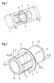
- the sleeve 5 has both a cylindrical, preferably hollow cylindrical body 6 as a preferably centrally arranged collar 7.
- the collar 7 has a collar width B 7 in the region of a cut separation between two partial material webs. Furthermore, the maximum collar diameter D 7 is smaller than or equal to the two outer diameter sleeves D 1 , D 2 (see FIG.
- the beads 10 which can be seen in FIG. 2 have straight-line bead contours 11, which are preferably aligned in or at least substantially in the longitudinal direction L (double arrow) of the sleeve 5.
- the bead contours 11 may also assume other contour shapes, for example curved, alone or in combination with each other.
- the sleeve 5 has six arranged on its circumference 9 and only partially visible beads 10. From a practical point of view, the sleeve 5 should have at least three such beads 10.
- the sleeve 5 is provided at its two-sided ends 12, 13, each with a chamfer 14, 15, which have a chamfer angle ⁇ in the range of 30 to 60 °.
- one half of the sleeve 5 have a different diameter than the other half of the sleeve 5, so that it clamps different degrees in the two winding tubes 1, 2.
- the sleeve 5 during the axial separation of the two contacting winding rolls 1, 2 is not undefined pulled out.
- the illustrated cores 1, 2 together with sleeve 5 are also particularly suitable for carrying out the method according to the invention.
- the invention provides a reel cutting machine of the type mentioned in such a way that disturbances in the winding of the winding rolls and in the further processing of the winding rolls are avoided.
Landscapes
- Replacement Of Web Rolls (AREA)
Applications Claiming Priority (1)
| Application Number | Priority Date | Filing Date | Title |
|---|---|---|---|
| DE200510000076 DE102005000076A1 (de) | 2005-06-15 | 2005-06-15 | Rollenvorrichtung und Verfahren zum gleichzeitigen Aufwickeln von mehreren nebeneinander laufenden Teil-Materialbahnen |
Publications (1)
| Publication Number | Publication Date |
|---|---|
| EP1733982A1 true EP1733982A1 (fr) | 2006-12-20 |
Family
ID=36975546
Family Applications (1)
| Application Number | Title | Priority Date | Filing Date |
|---|---|---|---|
| EP06111424A Withdrawn EP1733982A1 (fr) | 2005-06-15 | 2006-03-21 | Dispositif d'enroulage de bobines et méthode pour l'enroulement simultané de plusieurs parties de bande de materiau en mouvement côte à côte |
Country Status (2)
| Country | Link |
|---|---|
| EP (1) | EP1733982A1 (fr) |
| DE (1) | DE102005000076A1 (fr) |
Cited By (7)
| Publication number | Priority date | Publication date | Assignee | Title |
|---|---|---|---|---|
| WO2013022615A1 (fr) * | 2011-08-08 | 2013-02-14 | Eastman Kodak Company | Cœur sans encoche |
| EP2436628A3 (fr) * | 2010-09-30 | 2014-07-09 | Voith Patent GmbH | Procédé d'enroulement et dispositif de découpage de rouleaux |
| CN104495523A (zh) * | 2014-11-29 | 2015-04-08 | 东电化日东(上海)电能源有限公司 | 分切机用管芯结构及其转接器 |
| CN105417289A (zh) * | 2015-12-14 | 2016-03-23 | 东电化(上海)电能源有限公司 | 一种用于管芯与卷绕轴间的适配器 |
| CN110817594A (zh) * | 2019-11-06 | 2020-02-21 | 宁波爵盛科技有限公司 | 一种电线卷绕装置 |
| CN119218795A (zh) * | 2024-11-28 | 2024-12-31 | 浙江兆泽实业有限公司 | 一种pet膜生产用收卷设备 |
| CN120793608A (zh) * | 2025-09-12 | 2025-10-17 | 江西惠美兴科技有限公司 | 一种适用性强的感光干膜卷绕装置 |
Families Citing this family (1)
| Publication number | Priority date | Publication date | Assignee | Title |
|---|---|---|---|---|
| DE102019109640A1 (de) * | 2019-04-11 | 2020-10-15 | Guido Schneider | Modulare Mehrwegwickelhülse |
Citations (6)
| Publication number | Priority date | Publication date | Assignee | Title |
|---|---|---|---|---|
| US3371776A (en) * | 1967-04-27 | 1968-03-05 | Badger Plug Comp | Double plug for roll-supporting cores |
| GB1153885A (en) * | 1965-09-17 | 1969-05-29 | Pershke Ltd Frank F | Device for Locking a Hollow Core to a Drive Shaft |
| US4440357A (en) * | 1982-07-15 | 1984-04-03 | Visual Graphics Corporation | Mandrel and core assembly for large format cameras |
| EP0694494A1 (fr) * | 1994-07-28 | 1996-01-31 | Hoechst Aktiengesellschaft | Boulon de centrage |
| DE19960000A1 (de) * | 1999-12-13 | 2001-07-05 | Voith Sulzer Papiertech Patent | Rollenwickelvorrichtung, insbesondere für eine Rollenschneidmaschine |
| EP1314674A2 (fr) * | 2001-11-22 | 2003-05-28 | Saimatec Engineering Oy | Procédé et dispositif pour connecter entre eux des objets adjacents équipés de trous |
-
2005
- 2005-06-15 DE DE200510000076 patent/DE102005000076A1/de not_active Withdrawn
-
2006
- 2006-03-21 EP EP06111424A patent/EP1733982A1/fr not_active Withdrawn
Patent Citations (6)
| Publication number | Priority date | Publication date | Assignee | Title |
|---|---|---|---|---|
| GB1153885A (en) * | 1965-09-17 | 1969-05-29 | Pershke Ltd Frank F | Device for Locking a Hollow Core to a Drive Shaft |
| US3371776A (en) * | 1967-04-27 | 1968-03-05 | Badger Plug Comp | Double plug for roll-supporting cores |
| US4440357A (en) * | 1982-07-15 | 1984-04-03 | Visual Graphics Corporation | Mandrel and core assembly for large format cameras |
| EP0694494A1 (fr) * | 1994-07-28 | 1996-01-31 | Hoechst Aktiengesellschaft | Boulon de centrage |
| DE19960000A1 (de) * | 1999-12-13 | 2001-07-05 | Voith Sulzer Papiertech Patent | Rollenwickelvorrichtung, insbesondere für eine Rollenschneidmaschine |
| EP1314674A2 (fr) * | 2001-11-22 | 2003-05-28 | Saimatec Engineering Oy | Procédé et dispositif pour connecter entre eux des objets adjacents équipés de trous |
Cited By (7)
| Publication number | Priority date | Publication date | Assignee | Title |
|---|---|---|---|---|
| EP2436628A3 (fr) * | 2010-09-30 | 2014-07-09 | Voith Patent GmbH | Procédé d'enroulement et dispositif de découpage de rouleaux |
| WO2013022615A1 (fr) * | 2011-08-08 | 2013-02-14 | Eastman Kodak Company | Cœur sans encoche |
| CN104495523A (zh) * | 2014-11-29 | 2015-04-08 | 东电化日东(上海)电能源有限公司 | 分切机用管芯结构及其转接器 |
| CN105417289A (zh) * | 2015-12-14 | 2016-03-23 | 东电化(上海)电能源有限公司 | 一种用于管芯与卷绕轴间的适配器 |
| CN110817594A (zh) * | 2019-11-06 | 2020-02-21 | 宁波爵盛科技有限公司 | 一种电线卷绕装置 |
| CN119218795A (zh) * | 2024-11-28 | 2024-12-31 | 浙江兆泽实业有限公司 | 一种pet膜生产用收卷设备 |
| CN120793608A (zh) * | 2025-09-12 | 2025-10-17 | 江西惠美兴科技有限公司 | 一种适用性强的感光干膜卷绕装置 |
Also Published As
| Publication number | Publication date |
|---|---|
| DE102005000076A1 (de) | 2006-12-21 |
Similar Documents
| Publication | Publication Date | Title |
|---|---|---|
| DE60105027T2 (de) | Wickelwelle und wickler zum wickeln einer papierbahn | |
| EP3031758A1 (fr) | Arbre d'enroulement et procédé d'insertion d'un arbre d'enroulement dans un dispositif d'enroulement | |
| EP1733982A1 (fr) | Dispositif d'enroulage de bobines et méthode pour l'enroulement simultané de plusieurs parties de bande de materiau en mouvement côte à côte | |
| DE1574438A1 (de) | Dehnbarer Spanndorn fuer rohrfoermige Kerne | |
| EP1434731B1 (fr) | Bobine | |
| WO2019224370A1 (fr) | Douille, équipement d'enroulement et procédé destiné à enrouler plusieurs fois les unes sur les autres des bandes en enroulements de matériau | |
| EP1921034A2 (fr) | Bobineuse destinée à enrouler des bandes de matériaux de pièces fabriquées à partir d'une bande de matériau | |
| EP0886620B1 (fr) | Dispositif d'enroulement continu de bandes de papier coupees longitudinalement avec changement automatique des rouleaux a vitesse de la machine | |
| EP1176110B1 (fr) | Procédé et noyau d'enroulement pour éviter les erreurs d'enroulement dans une bande de matériau | |
| DE102011113182A1 (de) | Doppeltragwalzenroller | |
| EP1757545B1 (fr) | Dispositif d'enroulement d'une bande | |
| EP0876898B1 (fr) | Dispositif pour fabriquer une gaine tubulaire | |
| EP1818298B1 (fr) | Méthode et dispositif pour enrouler des bandes de parties de matériau sur des noyaux, pour former des rouleaux de partie de matériau | |
| EP0166795B1 (fr) | Procédé pour enrouler des bandes refendues | |
| EP1048773B1 (fr) | Support pour enroulement de fil textile | |
| EP3962848B1 (fr) | Poste de déroulement | |
| EP1876119B1 (fr) | Dispositif d'enroulement à rouleaux et procédé destiné à enrouler une bande de matériau | |
| EP1897831A2 (fr) | Procédé destiné au changement de rouleau dans un dispositif d'enroulement de rouleaux et dispositif d'enroulement de rouleaux pour l'enroulement d'une bande de matériau | |
| DE202008009998U1 (de) | Wickelmaschine zum kontinuierlichen Aufwickeln einer Materialbahn | |
| DE102008040350A1 (de) | Verfahren zum Aufwickeln einer laufenden Materialbahn sowie Wickelmaschine zur Durchführung des Verfahrens | |
| DE9418081U1 (de) | Wickelhilfe für Wickelmaschinen | |
| DE60021776T2 (de) | Kernrohrkonstruktion für wickelrollen aus papier oder anderem bahnförmigem material | |
| EP1847495A1 (fr) | Procédé, mandrin de bobinage et bobineuse destinés à l'embobinage d'au moins deux bandes de matériau passant l'une à côté de l'autre | |
| EP1650146A2 (fr) | Machine d'enroulement et noyau d'enroulement pour l'utilisation dans une machine d'enroulement | |
| DE10002022A1 (de) | Vorrichtung zum Einfügen eines Zwischenstreifens zwischen auf eine Transportspule aufzuwickelnde Lagen eines Profilstranges |
Legal Events
| Date | Code | Title | Description |
|---|---|---|---|
| PUAI | Public reference made under article 153(3) epc to a published international application that has entered the european phase |
Free format text: ORIGINAL CODE: 0009012 |
|
| AK | Designated contracting states |
Kind code of ref document: A1 Designated state(s): AT BE BG CH CY CZ DE DK EE ES FI FR GB GR HU IE IS IT LI LT LU LV MC NL PL PT RO SE SI SK TR |
|
| AX | Request for extension of the european patent |
Extension state: AL BA HR MK YU |
|
| 17P | Request for examination filed |
Effective date: 20070620 |
|
| AKX | Designation fees paid |
Designated state(s): AT DE FI IT |
|
| GRAP | Despatch of communication of intention to grant a patent |
Free format text: ORIGINAL CODE: EPIDOSNIGR1 |
|
| RTI1 | Title (correction) |
Free format text: REEL WINDING DEVICE FOR SIMULTANEOUSLY WINDING A PLURALITY OF SIDE BY SIDE RUNNING PARTIAL WEBS OF MATERIAL |
|
| STAA | Information on the status of an ep patent application or granted ep patent |
Free format text: STATUS: THE APPLICATION IS DEEMED TO BE WITHDRAWN |
|
| 18D | Application deemed to be withdrawn |
Effective date: 20090901 |