EP1734191A2 - Barrière de sécurité avec éléments en bois - Google Patents
Barrière de sécurité avec éléments en bois Download PDFInfo
- Publication number
- EP1734191A2 EP1734191A2 EP06009649A EP06009649A EP1734191A2 EP 1734191 A2 EP1734191 A2 EP 1734191A2 EP 06009649 A EP06009649 A EP 06009649A EP 06009649 A EP06009649 A EP 06009649A EP 1734191 A2 EP1734191 A2 EP 1734191A2
- Authority
- EP
- European Patent Office
- Prior art keywords
- restraint system
- vehicle restraint
- armierungsgurt
- wood
- profile
- Prior art date
- Legal status (The legal status is an assumption and is not a legal conclusion. Google has not performed a legal analysis and makes no representation as to the accuracy of the status listed.)
- Granted
Links
Images


Classifications
-
- E—FIXED CONSTRUCTIONS
- E01—CONSTRUCTION OF ROADS, RAILWAYS, OR BRIDGES
- E01F—ADDITIONAL WORK, SUCH AS EQUIPPING ROADS OR THE CONSTRUCTION OF PLATFORMS, HELICOPTER LANDING STAGES, SIGNS, SNOW FENCES, OR THE LIKE
- E01F15/00—Safety arrangements for slowing, redirecting or stopping errant vehicles, e.g. guard posts or bollards; Arrangements for reducing damage to roadside structures due to vehicular impact
- E01F15/02—Continuous barriers extending along roads or between traffic lanes
- E01F15/04—Continuous barriers extending along roads or between traffic lanes essentially made of longitudinal beams or rigid strips supported above ground at spaced points
- E01F15/0453—Rails of materials other than metal or concrete, e.g. wood, plastics; Rails of different materials, e.g. rubber-faced metal profiles, concrete-filled steel tubes
-
- E—FIXED CONSTRUCTIONS
- E01—CONSTRUCTION OF ROADS, RAILWAYS, OR BRIDGES
- E01F—ADDITIONAL WORK, SUCH AS EQUIPPING ROADS OR THE CONSTRUCTION OF PLATFORMS, HELICOPTER LANDING STAGES, SIGNS, SNOW FENCES, OR THE LIKE
- E01F15/00—Safety arrangements for slowing, redirecting or stopping errant vehicles, e.g. guard posts or bollards; Arrangements for reducing damage to roadside structures due to vehicular impact
- E01F15/02—Continuous barriers extending along roads or between traffic lanes
- E01F15/04—Continuous barriers extending along roads or between traffic lanes essentially made of longitudinal beams or rigid strips supported above ground at spaced points
- E01F15/0461—Supports, e.g. posts
Definitions
- the present invention relates to a vehicle restraint system for securing a roadway having at least one longitudinally extending restraint string and a plurality of posts supporting the restraint strand at a predetermined mounting height above a ground, the restraint strand comprising at least one solid wood element and at least one at least partially connected thereto Arm michsgurt and wherein the reinforcing belt is at least partially received in the wood element.
- Such a vehicle restraint system is known, for example, from the prior art according to the specification "GLISSI ⁇ RE DE SÉCURITÉ MIXTE MÉTAL-BOIS", CIRCULAIRE D 'AGRÉMENT N ° 92-58 DU 5 OCTOBRE 1992 (filed with the application documents for the official file).
- This specification shows in Figures 6 and 7 each have a wooden element which is formed on its side facing away from the roadway back with a milled groove. In this groove, a U-shaped reinforcing belt is used, which can be fastened via connecting struts both on post elements and on an adjacent wooden element Arm istsgurt assembly.
- a vehicle restraint system with wood elements in which the wood elements is provided in a connecting region to a respective post with metal profiles.
- the metal profiles serve on the one hand to reinforce the joint and on the other hand to connect two successive wooden elements.
- the wood elements are not reinforced, so that they can break completely in the event of an impact and therefore have only a very low vehicle retention.
- a vehicle restraint system of the type described in which the at least one wood element is formed with a longitudinally extending receiving slot which opens orthogonal to the longitudinal direction in the region of the underside of the wood element and is dimensioned such that it during assembly the Arm michsgurt receives, so that the wood element rests on the at least one Arm réellesgurt.
- the receiving slot By attaching the receiving slot according to the invention, it is initially possible to ram the post elements to measure in the ground during assembly of the vehicle restraint system at the installation site and then attach the dimensionally reinforcing belt to the post elements. Then individual wooden elements can be pushed onto the Arm michsgurt, wherein the respective receiving slot of a wooden element receives the Arm michsgurt. As a result, the wooden element is already on the Arm réellesgurt due to gravity and needs not to be kept further by a mechanic. Further assembly steps, such as the attachment of mounting screws, can then be easily done without major human effort.
- a development of the invention provides that the reinforcement belt is formed by a longitudinal profile, preferably a steel strip.
- a sufficient retention capacity of the vehicle restraint system can also be achieved.
- containment levels up to H2 according to DIN EN 1317-2 can be achieved, which is a very high value for a vehicle restraint system with wood elements.
- the wood element is formed like a trunk, wherein the receiving slot in which the wood element is arranged eccentrically.
- the eccentric arrangement of the receiving slot in the wooden element means that the slot is oriented, for example, after installation of the vehicle restraint system so that it runs parallel to a vertical center plane of the trunk-like wooden element and the back of the wooden element, that is away from the roadway, offset.
- a development of the invention provides that at least one profile element is provided for the connection of the retaining strand and posts or / and for connecting two successive wooden elements, which can be fastened to the Arm istsgurt.
- the profile element thus serves to connect two successive wooden elements and possibly also to connect the retaining strand with the post.
- posts are attached to each juncture of two successive wooden elements.
- the wood element has at least end-side recess areas, wherein the profile element is arranged in the recess area. This makes it possible to accommodate the profile elements within the contour of the wood elements, so as to reduce the required space of the vehicle restraint system.
- a development of the invention provides that the profile element is designed as a C-profile with successive directed C-legs and that for fastening to the post member a C-leg hintergeifende mounting plate is provided. This has the advantage that the mounting plate can be moved along the entire profile element and so a simple adjustment of the retaining strand is already possible to measure rammed into the ground post. Also by this measure, deformations of the retaining strand during assembly can be readily compensated, so that an additional drilling of mounting holes, as may be required in individual solutions from the prior art due to the deformations, is no longer necessary.
- a development of the invention provides that the mounting plate is connected by means of a breakaway head screw with the post element or connectable. With sufficiently high impact forces, the head of the breakaway head screw loosens from the shaft, so that the restraining strand separates from the post element and is held by adjacent post elements substantially in the mounting height. An impacting vehicle can not easily slide over the vehicle restraint system.
- profile elements with notch area, which facilitate bending deformation of the profile element and thus allow adjustment of the vehicle restraint system to a curvy road course with little effort.
- profile elements allow a deformation both for adaptation to a concave and a convex curve.
- this is provided with a longitudinal groove into which a reinforcement profile can be used.
- the reinforcing belt can be connected to the wood element by means of at least one connecting bolt, wherein the connecting bolt passes through the wood element and the reinforcing belt.
- the Arm istsgurt for receiving the connecting screw has a slot.
- the connecting screw for connecting the Arm michsgurts with the wood element at the same time serves for the connection of profile element and Arm michsgurt.
- a spacer for example a U-washer, can be inserted between the wooden element and the reinforcing belt in order to ensure a sufficient clamping between the profile element and the reinforcing belt.
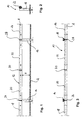
- FIG. 1 a vehicle restraint system according to the invention is shown in front view and generally designated 10.
- This comprises a along a longitudinal axis A extending in the longitudinal direction retaining strand 12, which is held by means of posts 14 and 16 at a predetermined mounting height H above a substrate U.
- the section of the retaining strand 12 shown in FIG. 1 is composed of several wooden elements 18, 20, 22 and 24 in a jerky manner.
- the posts 14 and 16 are attached to joints 26 and 28 at which two successive wooden elements 18 and 20 or 22 and 24 are interconnected in the following to be explained in detail. At a joint 30, however, the two consecutive wooden elements 20 and 22 are connected directly without additional posts.
- FIGS. 2 and 3 show a side view and a top view of the vehicle restraint system 10 according to FIG.
- the post element 20 is shown in detail in various views by way of example. It can be seen that the post element 20 is formed in the longitudinal direction with an eccentrically arranged receiving slot 32.
- This receiving slot 32 extends, as shown in Figure 5, in a substantially vertical direction and thus opens orthogonal to the longitudinal direction of the wood element in the region of its bottom 34.
- the eccentricity is a distance d of the receiving slot from a substantially vertical center plane of the wood element 20 determined. This offset distance d is, for example, in the range of 2 to 3 cm.
- the receiving slot has a base 36 which delimits upward in it.
- the wooden element 20 has end-side recessed areas 38 and 40, into which the receiving slot opens at the front. These recessed areas 38 and 40 are used to accommodate later explained in more detail profile elements, which then serve to connect two successive wooden elements or for attachment of the retaining strand 12 to posts. Further, in the wood element 20 connecting holes 42, 44 are provided, which are each formed at the opening portions with depressions 46. The connection bores 42 and 44 are substantially horizontal and orthogonal to the receiving slot 32.
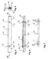
- FIG. 7 shows, in a reduced representation, a reinforcing belt 50, which is designed as a steel strip with a substantially rectangular cross section.
- the reinforcing belt 50 is dimensioned so that it fits into the receiving slot 32 with sufficient play. It has a series of mounting holes 52 and further has two connecting holes 54 and 56.
- the connecting holes 54 and 56 are formed as slots and correspond to the connecting holes 42 and 44 in the wood element 20, so that by inserting a connecting screw wood element 20 and Arm réellesgurt 50 tightly screw together. Possible deformations of the wood element 20 can be compensated over the slots.
- the mounting holes 52 are used to connect two Armsammlungsgurte together, as will be explained in more detail below.
- a C-profile element 62 For fixing the two wooden elements 20 and 22 together, a C-profile element 62, which is shown in Figure 9 in section.
- the C-profile element 62 overlaps with the two ends of Arm michsgurte 50 1 and 50 2 and is connected by fastening screws 64 with these.
- the fastening screws 64 pass through the fastening bores 52 shown in FIG. 7 in the reinforcing belts 50 1 and 50 2 .
- This type of attachment can be a particularly against tensile loads, relatively stable jerky composite restraint string 12 assemble.
- Fig.10 shows the joint area 28 at which the two wood elements 22 and 24 abut each other.
- This joint region 28 is formed in the same manner as the joint region 30, that is, the two Arm istsgurte 50 2 and 50 3 , which are respectively received in the wood element 22 and 24, are on the C-profile element 62 and associated connecting screws 64th screwed together as described with reference to Fig.8 and 9.
- the C-profile member 62 is connected to the post 16, as will be explained in detail below. It can be seen that the post 16 is reinforced with a reinforcing profile 66, which is received in a longitudinal groove 68 on the back of the post 16.
- a predetermined breaking screw 70 for fixing the C-profile element 62 to the post 16 is a predetermined breaking screw 70.
- the predetermined breaking screw is inserted into a mounting plate 72 which engages behind facing leg portions of the C-profile element 62.
- Figures 12 and 13 show this in detail.
- the mounting plate 72 has a slot 74 into which the fastening screw 70 is inserted and within which it is displaceable.
- the fixing plate 72 engages behind the two mutually facing leg sections 76 and 78.
- the predetermined breaking screw 70 has near its head a circumferential recess 80 which acts as a predetermined breaking point and from a certain load, a detachment of the head on the shaft of the predetermined breaking screw 70 allows.
- the posts 14, 16 and other posts are rammed to size in the underground U.
- the reinforcing profiles 66 serve for anchoring in the subsoil U and extend beyond the wooden bodies of the posts 14 and 16 into the underground U.
- the reinforcing straps 50 1 , 50 2 and 50 3 as well as further reinforcing straps on the posts 14, 16 and attached to other posts or fastened together, as shown in Fig.8 and 9.
- the profile elements 62 as shown in Figure 11 to 13 via predetermined breaking screws 70 to the posts 14, 16 and attached to other posts.
- the predetermined breaking screw 70 with the mounting plate 72 can be displaced in the longitudinal direction within the C-profile 62 and so any dimensional inaccuracies between fastening straps 50 1 to 50 3 and the position of rammed to measure posts 14 and 16th and other posts can be compensated.
- height fluctuations can be compensated to a certain extent, in which the fastening screws 70 are displaced within the slot 74 in each case. This allows the individual Armsammlungsgurte be screwed with relatively little installation effort with the post.
- the wooden elements can be pushed onto the Arm réellesgurte by the receiving slot of a wooden element is pushed onto the respective Arm réellesgurt.
- the Arm réellesgurte then come into contact with the base 36 of the respective receiving slot 32 so that the wood elements rest on the Arm réellesgurten.
- the connecting screws are inserted into the wooden elements, so that they pass through the slots 54 and 56.
- the slots 54 and 56 provide appropriate tolerance to compensate for possible deformations of the wood elements can.
- posts can be attached to any joints.
- the vehicle restraint system according to the invention is thus relatively easy to install and has no susceptibility to dimensional inaccuracies, the caused by natural deformation of the wood elements. Due to the variability in the assembly, such deformations can be easily compensated with the vehicle restraint system 10 according to the invention.
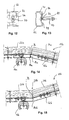
- Figures 14 and 15 show a joint which is slightly modified from the joint of Figure 10. It can be seen that in the joint according to FIGS. 14 and 15, two wood elements 22a and 24a or 22b and 24b are each angled away from one another. Such arrangements are required, for example, when the vehicle restraint system is used to secure curved roads.
- the arrangement according to FIG. 14 shows an installation with a convex course of the vehicle restraint system, whereas the arrangement according to FIG. 15 shows a concave course of the vehicle restraint system.
- the post 16a is no longer located approximately in the region of the center of the profile element 62a, but rather was offset to the left.
- a cut-in region 84a is provided, i. a part of the C-profile is miter cut, leaving the base of the C-profile unchanged.
- the C-profile can be deformed in the manner shown in FIG. 14 about the bending axis B which is orthogonal to the plane of the drawing, so that the two wooden elements 22a and 24a can be curved in a convex shape relative to one another.
- FIG. 14 further shows that the incision region 84 is deformed so strongly that the two cut edges almost come into mutual contact with each other. It is possible to weld the two cut edges together, as indicated at 86a. However, this is only an optional feature to further increase the stability of the vehicle restraint system 10a.
- FIG. 15 now shows a concave profile of the vehicle restraint system 10b.
- the profile element 62b is provided with a notch portion 84b, which allows a corresponding deformation.
- the end portions of the wood members 22b and 24b are chamfered to allow a corresponding deformation.
- Figures 16 to 19 show a second embodiment of the invention.
- the same reference numerals are used for the same effect or the same components, as for the description of the first embodiment according to Figures 1 to 15, but with the lowercase letter "a" readjusted. To avoid repetition, the differences to the first exemplary embodiment should be considered alone.
- FIGS. 16 to 19 Essentially two notable differences from the first embodiment according to FIGS. 1 to 15 can be seen in FIGS. 16 to 19.
- the first difference is that the connecting screws 58a and 60a for connecting the wooden element and reinforcing straps 50a 2 , 50a 3 are not separated Longitudinal holes of the respective Arm michsgurts 50a 2 , and 50a 3 run and are not arranged outside of the recess portion 40 a. Rather, the connecting screws 58a and 60a are also used to connect Arm michsgurt 50a 2 or 50a 3 and profile element 62a.
- a spacer element 90a is inserted between the wooden element 20a or 22a and the reinforcing belt 50a 2 or 50a 3 .
- the same also applies to the post-free connection of the two wood elements 22a and 24a according to FIG. 19.
- FIG. 17 shows that the reinforcement profile 66a in the post 16a does not necessarily have to extend to its upper end, but instead can terminate at a distance from the upper end. As a result, the upper portion of the post element remains nick-free and intact, giving the post element a familiar visual appearance.
- the second embodiment according to FIGS. 16 to 19 is further simplified with respect to the first embodiment according to FIGS. 1 to 15 with regard to assembly, since fewer screwing operations are required.
- One of the connecting screws 64a preferably replaced in each case the middle of a three connecting screws 64a, which serves to connect wood element 20a or 22a and the respective Arm istsgurt 50a 2 and 50a 3 .
Landscapes
- Engineering & Computer Science (AREA)
- Architecture (AREA)
- Civil Engineering (AREA)
- Structural Engineering (AREA)
- Life Sciences & Earth Sciences (AREA)
- Wood Science & Technology (AREA)
- Road Paving Structures (AREA)
- Refuge Islands, Traffic Blockers, Or Guard Fence (AREA)
- Joining Of Building Structures In Genera (AREA)
Applications Claiming Priority (1)
| Application Number | Priority Date | Filing Date | Title |
|---|---|---|---|
| DE102005026969A DE102005026969A1 (de) | 2005-06-10 | 2005-06-10 | Fahrzeugrückhaltesystem mit Holzelementen zum Absichern einer Fahrbahn |
Publications (3)
| Publication Number | Publication Date |
|---|---|
| EP1734191A2 true EP1734191A2 (fr) | 2006-12-20 |
| EP1734191A3 EP1734191A3 (fr) | 2007-01-03 |
| EP1734191B1 EP1734191B1 (fr) | 2010-03-10 |
Family
ID=36954786
Family Applications (1)
| Application Number | Title | Priority Date | Filing Date |
|---|---|---|---|
| EP06009649A Not-in-force EP1734191B1 (fr) | 2005-06-10 | 2006-05-10 | Barrière de sécurité avec éléments en bois |
Country Status (4)
| Country | Link |
|---|---|
| EP (1) | EP1734191B1 (fr) |
| AT (1) | ATE460535T1 (fr) |
| DE (2) | DE102005026969A1 (fr) |
| ES (1) | ES2339958T3 (fr) |
Cited By (1)
| Publication number | Priority date | Publication date | Assignee | Title |
|---|---|---|---|---|
| ES2279734A1 (es) * | 2007-01-19 | 2007-08-16 | Hierros Y Aplanaciones, S.A. (Hiasa) | Barrera de seguridad para carreteras mixta de madera y metal para contencion de impacto alteral de vehiculos, con cualidades esteticas y capacidad de contencion y redireccionamiento. |
Family Cites Families (5)
| Publication number | Priority date | Publication date | Assignee | Title |
|---|---|---|---|---|
| FR2718473B1 (fr) * | 1994-04-07 | 1996-07-19 | France Bois Impregnes Sa | Glissière de sécurité pour bordures de voies de circulation. |
| FR2793822B1 (fr) * | 1999-05-21 | 2001-06-22 | Gaillard Rondino | Glissiere de securite bois sur appuis a entraxes variables |
| FR2811344B1 (fr) * | 2000-07-07 | 2008-05-30 | Claude Alix Georges Pomero | Glissiere de securite routiere en bois avec renfort metal continu insere dans le rondin |
| FR2833630B1 (fr) * | 2001-12-18 | 2004-09-10 | Profiles Du Ct | Glissiere de securite bois |
| DE202004013606U1 (de) * | 2004-08-30 | 2004-10-28 | SGGT Straßenausstattungen GmbH | Passive Schutzeinrichtung neben einer Fahrbahn einer Kraftfahrzeugstraße |
-
2005
- 2005-06-10 DE DE102005026969A patent/DE102005026969A1/de not_active Withdrawn
-
2006
- 2006-05-10 DE DE502006006373T patent/DE502006006373D1/de active Active
- 2006-05-10 AT AT06009649T patent/ATE460535T1/de active
- 2006-05-10 ES ES06009649T patent/ES2339958T3/es active Active
- 2006-05-10 EP EP06009649A patent/EP1734191B1/fr not_active Not-in-force
Cited By (4)
| Publication number | Priority date | Publication date | Assignee | Title |
|---|---|---|---|---|
| ES2279734A1 (es) * | 2007-01-19 | 2007-08-16 | Hierros Y Aplanaciones, S.A. (Hiasa) | Barrera de seguridad para carreteras mixta de madera y metal para contencion de impacto alteral de vehiculos, con cualidades esteticas y capacidad de contencion y redireccionamiento. |
| EP1947244A1 (fr) * | 2007-01-19 | 2008-07-23 | Hierros y Aplanaciones, S.A. (HIASA) | Glissière de sécurité en bois et métal mélangés pour routes pour la contention d'un impact latéral de véhicule, présentant des qualités esthétiques et une capacité de contention et de redirection |
| WO2008087232A1 (fr) * | 2007-01-19 | 2008-07-24 | Hierros Y Aplanaciones, S.A. (Hiasa) | Barrière de sécurité pour routes en bois et métal servant à contenir les chocs latéraux de véhicules, à qualité esthétique et capacité de régulation et de redirectionnement |
| ES2279734B2 (es) * | 2007-01-19 | 2008-11-01 | Hierros Y Aplanaciones, S.A. (Hiasa) | Barrera de seguridad para carreteras mixta de madera y metal para contencion de impacto lateral de vehiculos, con cualidades esteticas y capacidad de contencion y redireccionamiento. |
Also Published As
| Publication number | Publication date |
|---|---|
| DE102005026969A1 (de) | 2006-12-14 |
| DE502006006373D1 (de) | 2010-04-22 |
| ES2339958T3 (es) | 2010-05-27 |
| EP1734191B1 (fr) | 2010-03-10 |
| EP1734191A3 (fr) | 2007-01-03 |
| ATE460535T1 (de) | 2010-03-15 |
Similar Documents
| Publication | Publication Date | Title |
|---|---|---|
| DE102008023340B4 (de) | Aggregateträger für ein Getriebe eines Kraftfahrzeugs | |
| DE102018221183B3 (de) | Justierbeschlag und Tragsystem für Solarmodule | |
| EP1977935B1 (fr) | Structure de cadre d'un véhicule automobile et crashbox correspondante | |
| DE202008011312U1 (de) | Verriegelungssystem zum Verriegeln von flächigen Solarmodulen | |
| EP1647782A2 (fr) | Dispositif de support d'au moins un collecteur solaire | |
| EP2455546A1 (fr) | Agencement de poteau pour une construction de glissière de sécurité et construction de glissière de sécurité pour sécuriser des bandes de roulement sur des chantiers | |
| DE202006020257U1 (de) | Verkehrs-Leit-Einrichtung | |
| DE102013021885B4 (de) | Vorrichtung zur Befestigung eines Fensters oder einer Tür in einer Wandöffnung und Verfahren zum Einbau eines Fensters oder einer Tür in eine Wandöffnung | |
| EP1544377B1 (fr) | Element de coffrage pour murs courbes | |
| DE102005038150B4 (de) | Schlussquerträger für ein Nutzfahrzeug | |
| EP1926859B1 (fr) | Barriere de protection en madriers | |
| DE102017216892A1 (de) | Gerüstelement zur Anbindung an eine scheibenförmige Anschlussplatte sowie Gerüst-Teil mit einem solchen Gerüstelement | |
| EP3527734B1 (fr) | Caniveau d'écoulement des eaux pourvu de cadre de montage | |
| DE20003056U1 (de) | Befestigungsvorrichtung für plattenförmige Fassadenelemente | |
| EP1734191B1 (fr) | Barrière de sécurité avec éléments en bois | |
| DE102007063511B4 (de) | Schutzeinrichtung an Verkehrswegen | |
| DE10356220B4 (de) | Sicherungseinrichtung für befahrbare oder begehbare Flächen | |
| EP2262953A1 (fr) | Système de retenue pour véhicule | |
| DE202013011471U1 (de) | Vorrichtung zur Befestigung eines Fensters oder einer Tür in einer Wandöffnung | |
| DE102021128740A1 (de) | Dachdurchdringungsfreie Anschlaganordnung sowie daraus gebildete Anschlageinheit | |
| DE102018203080B4 (de) | Fundamentsystem für die lagerung von flächig nebeneinander angeordneten solarpaneelen | |
| EP3611305A1 (fr) | Élément mural pour un mur de gestion et/ou d'arrêt de trafic | |
| AT528117B1 (de) | Vorrichtung zur Halterung von in einer Reihe angeordneten Solarmodulen | |
| EP4074917B1 (fr) | Montage d'une structure de protection contre les chutes à un cadre au moyen d'un corps de fixation sans connexion directe à un dispositif de fixation de cadre | |
| DE102006000816B3 (de) | Führungsschiene für den Umlenkbeschlag eines Sicherheitsgurtes für Kraftfahrzeuge |
Legal Events
| Date | Code | Title | Description |
|---|---|---|---|
| PUAI | Public reference made under article 153(3) epc to a published international application that has entered the european phase |
Free format text: ORIGINAL CODE: 0009012 |
|
| PUAL | Search report despatched |
Free format text: ORIGINAL CODE: 0009013 |
|
| AK | Designated contracting states |
Kind code of ref document: A2 Designated state(s): AT BE BG CH CY CZ DE DK EE ES FI FR GB GR HU IE IS IT LI LT LU LV MC NL PL PT RO SE SI SK TR |
|
| AX | Request for extension of the european patent |
Extension state: AL BA HR MK YU |
|
| AK | Designated contracting states |
Kind code of ref document: A3 Designated state(s): AT BE BG CH CY CZ DE DK EE ES FI FR GB GR HU IE IS IT LI LT LU LV MC NL PL PT RO SE SI SK TR |
|
| AX | Request for extension of the european patent |
Extension state: AL BA HR MK YU |
|
| RIC1 | Information provided on ipc code assigned before grant |
Ipc: E01F 15/04 20060101AFI20061124BHEP |
|
| 17P | Request for examination filed |
Effective date: 20070703 |
|
| AKX | Designation fees paid |
Designated state(s): AT BE BG CH CY CZ DE DK EE ES FI FR GB GR HU IE IS IT LI LT LU LV MC NL PL PT RO SE SI SK TR |
|
| 17Q | First examination report despatched |
Effective date: 20070912 |
|
| GRAP | Despatch of communication of intention to grant a patent |
Free format text: ORIGINAL CODE: EPIDOSNIGR1 |
|
| GRAS | Grant fee paid |
Free format text: ORIGINAL CODE: EPIDOSNIGR3 |
|
| GRAA | (expected) grant |
Free format text: ORIGINAL CODE: 0009210 |
|
| AK | Designated contracting states |
Kind code of ref document: B1 Designated state(s): AT BE BG CH CY CZ DE DK EE ES FI FR GB GR HU IE IS IT LI LT LU LV MC NL PL PT RO SE SI SK TR |
|
| REG | Reference to a national code |
Ref country code: GB Ref legal event code: FG4D Free format text: NOT ENGLISH |
|
| REG | Reference to a national code |
Ref country code: CH Ref legal event code: EP |
|
| REG | Reference to a national code |
Ref country code: IE Ref legal event code: FG4D |
|
| REF | Corresponds to: |
Ref document number: 502006006373 Country of ref document: DE Date of ref document: 20100422 Kind code of ref document: P |
|
| REG | Reference to a national code |
Ref country code: ES Ref legal event code: FG2A Ref document number: 2339958 Country of ref document: ES Kind code of ref document: T3 |
|
| REG | Reference to a national code |
Ref country code: NL Ref legal event code: VDEP Effective date: 20100310 |
|
| PG25 | Lapsed in a contracting state [announced via postgrant information from national office to epo] |
Ref country code: LT Free format text: LAPSE BECAUSE OF FAILURE TO SUBMIT A TRANSLATION OF THE DESCRIPTION OR TO PAY THE FEE WITHIN THE PRESCRIBED TIME-LIMIT Effective date: 20100310 |
|
| LTIE | Lt: invalidation of european patent or patent extension |
Effective date: 20100310 |
|
| PG25 | Lapsed in a contracting state [announced via postgrant information from national office to epo] |
Ref country code: PL Free format text: LAPSE BECAUSE OF FAILURE TO SUBMIT A TRANSLATION OF THE DESCRIPTION OR TO PAY THE FEE WITHIN THE PRESCRIBED TIME-LIMIT Effective date: 20100310 Ref country code: SI Free format text: LAPSE BECAUSE OF FAILURE TO SUBMIT A TRANSLATION OF THE DESCRIPTION OR TO PAY THE FEE WITHIN THE PRESCRIBED TIME-LIMIT Effective date: 20100310 Ref country code: LV Free format text: LAPSE BECAUSE OF FAILURE TO SUBMIT A TRANSLATION OF THE DESCRIPTION OR TO PAY THE FEE WITHIN THE PRESCRIBED TIME-LIMIT Effective date: 20100310 Ref country code: FI Free format text: LAPSE BECAUSE OF FAILURE TO SUBMIT A TRANSLATION OF THE DESCRIPTION OR TO PAY THE FEE WITHIN THE PRESCRIBED TIME-LIMIT Effective date: 20100310 |
|
| REG | Reference to a national code |
Ref country code: IE Ref legal event code: FD4D |
|
| PG25 | Lapsed in a contracting state [announced via postgrant information from national office to epo] |
Ref country code: CY Free format text: LAPSE BECAUSE OF FAILURE TO SUBMIT A TRANSLATION OF THE DESCRIPTION OR TO PAY THE FEE WITHIN THE PRESCRIBED TIME-LIMIT Effective date: 20100310 Ref country code: EE Free format text: LAPSE BECAUSE OF FAILURE TO SUBMIT A TRANSLATION OF THE DESCRIPTION OR TO PAY THE FEE WITHIN THE PRESCRIBED TIME-LIMIT Effective date: 20100310 Ref country code: GR Free format text: LAPSE BECAUSE OF FAILURE TO SUBMIT A TRANSLATION OF THE DESCRIPTION OR TO PAY THE FEE WITHIN THE PRESCRIBED TIME-LIMIT Effective date: 20100611 Ref country code: SE Free format text: LAPSE BECAUSE OF FAILURE TO SUBMIT A TRANSLATION OF THE DESCRIPTION OR TO PAY THE FEE WITHIN THE PRESCRIBED TIME-LIMIT Effective date: 20100310 Ref country code: RO Free format text: LAPSE BECAUSE OF FAILURE TO SUBMIT A TRANSLATION OF THE DESCRIPTION OR TO PAY THE FEE WITHIN THE PRESCRIBED TIME-LIMIT Effective date: 20100310 Ref country code: NL Free format text: LAPSE BECAUSE OF FAILURE TO SUBMIT A TRANSLATION OF THE DESCRIPTION OR TO PAY THE FEE WITHIN THE PRESCRIBED TIME-LIMIT Effective date: 20100310 |
|
| BERE | Be: lapsed |
Owner name: VOLKMANN & ROSSBACH G.M.B.H. & CO. KG Effective date: 20100531 |
|
| PG25 | Lapsed in a contracting state [announced via postgrant information from national office to epo] |
Ref country code: SK Free format text: LAPSE BECAUSE OF FAILURE TO SUBMIT A TRANSLATION OF THE DESCRIPTION OR TO PAY THE FEE WITHIN THE PRESCRIBED TIME-LIMIT Effective date: 20100310 Ref country code: BG Free format text: LAPSE BECAUSE OF FAILURE TO SUBMIT A TRANSLATION OF THE DESCRIPTION OR TO PAY THE FEE WITHIN THE PRESCRIBED TIME-LIMIT Effective date: 20100610 Ref country code: CZ Free format text: LAPSE BECAUSE OF FAILURE TO SUBMIT A TRANSLATION OF THE DESCRIPTION OR TO PAY THE FEE WITHIN THE PRESCRIBED TIME-LIMIT Effective date: 20100310 Ref country code: IS Free format text: LAPSE BECAUSE OF FAILURE TO SUBMIT A TRANSLATION OF THE DESCRIPTION OR TO PAY THE FEE WITHIN THE PRESCRIBED TIME-LIMIT Effective date: 20100710 |
|
| PLBI | Opposition filed |
Free format text: ORIGINAL CODE: 0009260 |
|
| PG25 | Lapsed in a contracting state [announced via postgrant information from national office to epo] |
Ref country code: MC Free format text: LAPSE BECAUSE OF NON-PAYMENT OF DUE FEES Effective date: 20100531 |
|
| REG | Reference to a national code |
Ref country code: CH Ref legal event code: PL |
|
| 26 | Opposition filed |
Opponent name: SGGT STRASSENAUSSTATTUNGEN GMBH Effective date: 20101210 |
|
| PLAX | Notice of opposition and request to file observation + time limit sent |
Free format text: ORIGINAL CODE: EPIDOSNOBS2 |
|
| PG25 | Lapsed in a contracting state [announced via postgrant information from national office to epo] |
Ref country code: PT Free format text: LAPSE BECAUSE OF FAILURE TO SUBMIT A TRANSLATION OF THE DESCRIPTION OR TO PAY THE FEE WITHIN THE PRESCRIBED TIME-LIMIT Effective date: 20100712 Ref country code: IE Free format text: LAPSE BECAUSE OF FAILURE TO SUBMIT A TRANSLATION OF THE DESCRIPTION OR TO PAY THE FEE WITHIN THE PRESCRIBED TIME-LIMIT Effective date: 20100310 Ref country code: DK Free format text: LAPSE BECAUSE OF FAILURE TO SUBMIT A TRANSLATION OF THE DESCRIPTION OR TO PAY THE FEE WITHIN THE PRESCRIBED TIME-LIMIT Effective date: 20100310 |
|
| GBPC | Gb: european patent ceased through non-payment of renewal fee |
Effective date: 20100610 |
|
| PG25 | Lapsed in a contracting state [announced via postgrant information from national office to epo] |
Ref country code: CH Free format text: LAPSE BECAUSE OF NON-PAYMENT OF DUE FEES Effective date: 20100531 Ref country code: LI Free format text: LAPSE BECAUSE OF NON-PAYMENT OF DUE FEES Effective date: 20100531 |
|
| PG25 | Lapsed in a contracting state [announced via postgrant information from national office to epo] |
Ref country code: BE Free format text: LAPSE BECAUSE OF NON-PAYMENT OF DUE FEES Effective date: 20100531 |
|
| PLBB | Reply of patent proprietor to notice(s) of opposition received |
Free format text: ORIGINAL CODE: EPIDOSNOBS3 |
|
| PG25 | Lapsed in a contracting state [announced via postgrant information from national office to epo] |
Ref country code: GB Free format text: LAPSE BECAUSE OF NON-PAYMENT OF DUE FEES Effective date: 20100610 |
|
| PG25 | Lapsed in a contracting state [announced via postgrant information from national office to epo] |
Ref country code: HU Free format text: LAPSE BECAUSE OF FAILURE TO SUBMIT A TRANSLATION OF THE DESCRIPTION OR TO PAY THE FEE WITHIN THE PRESCRIBED TIME-LIMIT Effective date: 20100911 Ref country code: LU Free format text: LAPSE BECAUSE OF NON-PAYMENT OF DUE FEES Effective date: 20100510 |
|
| PG25 | Lapsed in a contracting state [announced via postgrant information from national office to epo] |
Ref country code: TR Free format text: LAPSE BECAUSE OF FAILURE TO SUBMIT A TRANSLATION OF THE DESCRIPTION OR TO PAY THE FEE WITHIN THE PRESCRIBED TIME-LIMIT Effective date: 20100310 |
|
| REG | Reference to a national code |
Ref country code: AT Ref legal event code: MM01 Ref document number: 460535 Country of ref document: AT Kind code of ref document: T Effective date: 20110510 |
|
| PLCK | Communication despatched that opposition was rejected |
Free format text: ORIGINAL CODE: EPIDOSNREJ1 |
|
| PGFP | Annual fee paid to national office [announced via postgrant information from national office to epo] |
Ref country code: ES Payment date: 20120525 Year of fee payment: 7 |
|
| PG25 | Lapsed in a contracting state [announced via postgrant information from national office to epo] |
Ref country code: AT Free format text: LAPSE BECAUSE OF NON-PAYMENT OF DUE FEES Effective date: 20110510 |
|
| PLBN | Opposition rejected |
Free format text: ORIGINAL CODE: 0009273 |
|
| STAA | Information on the status of an ep patent application or granted ep patent |
Free format text: STATUS: OPPOSITION REJECTED |
|
| 27O | Opposition rejected |
Effective date: 20121207 |
|
| REG | Reference to a national code |
Ref country code: DE Ref legal event code: R100 Ref document number: 502006006373 Country of ref document: DE Effective date: 20121207 |
|
| PGFP | Annual fee paid to national office [announced via postgrant information from national office to epo] |
Ref country code: IT Payment date: 20130525 Year of fee payment: 8 |
|
| PGFP | Annual fee paid to national office [announced via postgrant information from national office to epo] |
Ref country code: DE Payment date: 20140528 Year of fee payment: 9 |
|
| PGFP | Annual fee paid to national office [announced via postgrant information from national office to epo] |
Ref country code: FR Payment date: 20140528 Year of fee payment: 9 |
|
| PG25 | Lapsed in a contracting state [announced via postgrant information from national office to epo] |
Ref country code: IT Free format text: LAPSE BECAUSE OF NON-PAYMENT OF DUE FEES Effective date: 20140510 |
|
| REG | Reference to a national code |
Ref country code: ES Ref legal event code: FD2A Effective date: 20150626 |
|
| PG25 | Lapsed in a contracting state [announced via postgrant information from national office to epo] |
Ref country code: ES Free format text: LAPSE BECAUSE OF NON-PAYMENT OF DUE FEES Effective date: 20140511 |
|
| REG | Reference to a national code |
Ref country code: DE Ref legal event code: R119 Ref document number: 502006006373 Country of ref document: DE |
|
| REG | Reference to a national code |
Ref country code: FR Ref legal event code: ST Effective date: 20160129 |
|
| PG25 | Lapsed in a contracting state [announced via postgrant information from national office to epo] |
Ref country code: DE Free format text: LAPSE BECAUSE OF NON-PAYMENT OF DUE FEES Effective date: 20151201 |
|
| PG25 | Lapsed in a contracting state [announced via postgrant information from national office to epo] |
Ref country code: FR Free format text: LAPSE BECAUSE OF NON-PAYMENT OF DUE FEES Effective date: 20150601 |