EP1734273A2 - Dispositif de commande pour un embrayage - Google Patents
Dispositif de commande pour un embrayage Download PDFInfo
- Publication number
- EP1734273A2 EP1734273A2 EP06009818A EP06009818A EP1734273A2 EP 1734273 A2 EP1734273 A2 EP 1734273A2 EP 06009818 A EP06009818 A EP 06009818A EP 06009818 A EP06009818 A EP 06009818A EP 1734273 A2 EP1734273 A2 EP 1734273A2
- Authority
- EP
- European Patent Office
- Prior art keywords
- clutch
- release lever
- lever
- actuating
- spring
- Prior art date
- Legal status (The legal status is an assumption and is not a legal conclusion. Google has not performed a legal analysis and makes no representation as to the accuracy of the status listed.)
- Withdrawn
Links
Images




Classifications
-
- F—MECHANICAL ENGINEERING; LIGHTING; HEATING; WEAPONS; BLASTING
- F16—ENGINEERING ELEMENTS AND UNITS; GENERAL MEASURES FOR PRODUCING AND MAINTAINING EFFECTIVE FUNCTIONING OF MACHINES OR INSTALLATIONS; THERMAL INSULATION IN GENERAL
- F16D—COUPLINGS FOR TRANSMITTING ROTATION; CLUTCHES; BRAKES
- F16D28/00—Electrically-actuated clutches
-
- F—MECHANICAL ENGINEERING; LIGHTING; HEATING; WEAPONS; BLASTING
- F16—ENGINEERING ELEMENTS AND UNITS; GENERAL MEASURES FOR PRODUCING AND MAINTAINING EFFECTIVE FUNCTIONING OF MACHINES OR INSTALLATIONS; THERMAL INSULATION IN GENERAL
- F16D—COUPLINGS FOR TRANSMITTING ROTATION; CLUTCHES; BRAKES
- F16D23/00—Details of mechanically-actuated clutches not specific for one distinct type
- F16D23/12—Mechanical clutch-actuating mechanisms arranged outside the clutch as such
-
- F—MECHANICAL ENGINEERING; LIGHTING; HEATING; WEAPONS; BLASTING
- F16—ENGINEERING ELEMENTS AND UNITS; GENERAL MEASURES FOR PRODUCING AND MAINTAINING EFFECTIVE FUNCTIONING OF MACHINES OR INSTALLATIONS; THERMAL INSULATION IN GENERAL
- F16D—COUPLINGS FOR TRANSMITTING ROTATION; CLUTCHES; BRAKES
- F16D23/00—Details of mechanically-actuated clutches not specific for one distinct type
- F16D23/12—Mechanical clutch-actuating mechanisms arranged outside the clutch as such
- F16D2023/126—Actuation by rocker lever; Rocker levers therefor
-
- F—MECHANICAL ENGINEERING; LIGHTING; HEATING; WEAPONS; BLASTING
- F16—ENGINEERING ELEMENTS AND UNITS; GENERAL MEASURES FOR PRODUCING AND MAINTAINING EFFECTIVE FUNCTIONING OF MACHINES OR INSTALLATIONS; THERMAL INSULATION IN GENERAL
- F16D—COUPLINGS FOR TRANSMITTING ROTATION; CLUTCHES; BRAKES
- F16D2125/00—Components of actuators
- F16D2125/18—Mechanical mechanisms
- F16D2125/58—Mechanical mechanisms transmitting linear movement
- F16D2125/64—Levers
-
- F—MECHANICAL ENGINEERING; LIGHTING; HEATING; WEAPONS; BLASTING
- F16—ENGINEERING ELEMENTS AND UNITS; GENERAL MEASURES FOR PRODUCING AND MAINTAINING EFFECTIVE FUNCTIONING OF MACHINES OR INSTALLATIONS; THERMAL INSULATION IN GENERAL
- F16D—COUPLINGS FOR TRANSMITTING ROTATION; CLUTCHES; BRAKES
- F16D2125/00—Components of actuators
- F16D2125/18—Mechanical mechanisms
- F16D2125/58—Mechanical mechanisms transmitting linear movement
- F16D2125/64—Levers
- F16D2125/645—Levers with variable leverage, e.g. movable fulcrum
Definitions
- the present invention relates to a clutch actuating device according to the preamble of patent claim 1.
- clutches have been operated for example by means of a lever which has a fixed lever length and could be driven for example by means of an electric motor drive to open and / or close the clutch. If now over the travel of the clutch actuation a variable actuation force had to be applied, so for this purpose, the electric motor to provide a correspondingly high torque available, supplied with corresponding current values.
- Another possibility of the clutch actuation for example, in the form of a driven by an electric motor Gottausgurers, in which case the electric motor must be energized with high current values in order to provide correspondingly high output torques available.
- the lever system known from this publication is applied to the force application point of the actuating force in the lever arm 7a with a predeterminable force by the energy storage 9 (eg a spring).
- the energy storage 9 eg a spring
- On the output side that is, for example, on the side of a thrust bearing 11, a corresponding reaction force complementary to the spring force introduced into the actuating lever acts. Since the actuating lever is supported on a lever pivot 10, prevails at this support point at a lever length ratio of 1: 1 to form an equilibrium of forces corresponding to the double spring force reaction force.
- the object of the present invention is to provide a release system in the form of a clutch actuator, which requires a small actuation force in confined space conditions.
- the present invention can also be used for an actuation of a transmission brake.
- the clutch actuating device in particular for actuating a clutch or a transmission brake of a vehicle, at least one spring, the spring force for actuating the clutch by means of an associated mechanical power transmission path to the clutch is transferable, wherein the power transmission path comprises at least one displaceable force transmission element which is formed as a tangential to a rotational axis of the clutch bearing release lever.
- the release system is arranged rotatably about the central axis and can also be operated rotationally.
- the one or more release levers are arranged tangentially about the axis of rotation of the clutch.
- the plurality of release levers are provided four to eight times circumferentially evenly distributed, the release levers are preferably operated by a running unit, which forms a point-shaped contact point with the release lever.
- the running unit is preferably moved on a circular path and actuates the release lever, which is mounted linearly at two further support points.
- the circumference of a roller of the running unit, which forms the contact point to the release lever, is preferably profiled arcuate.
- all running units of all release levers are mounted in a common bearing cage, which can advantageously be actuated by means of an electric motor, d. H. is rotatable.
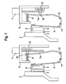
- FIG. 1 the basic structure of a lever system for actuating a clutch in the form of a wet clutch with a disk pack 23 and a transmission brake according to a first embodiment is shown, wherein the clutch actuating device shown therein within a short cylindrical space can be accommodated.
- an energy store 9 preferably in the form of a spring or a plate spring, is provided on a support 8, for example a housing of the coupling, which acts on one end of a lever arm 7a of a release lever (in the top of FIG. 1) and a corresponding actuation - or spring force initiates.
- a roller system 13 is movable by means of an electric motor 1 such that a pivot point 10 along the lever arm 7a can be displaced, as can be seen well in the two representations of Figure 1.
- the roller system 13 In the left-hand illustration of FIG. 1, the roller system 13 is located at the upper end of the lever arm 7a, whereas in the right-hand illustration the roller system 13 is moved downwards.
- the clutch In the right-hand illustration, the clutch is actuated by acting on the upper end of the lever arm 7a by means of the energy accumulator 9, which force is introduced at the lower end, at a support point 12, into the axial bearing 11 of the release spring 5.
- the release spring or disc spring 5 then also presses axially on the pressure plate 4, so that the clutch disc 3 between the pressure plate 4 and the counter-pressure plate 2 is held accordingly.
- the release spring 5 is mounted on a clutch cover 6.
- the roller system 13 runs along the support 8. By displacement of the pivot point 10 by the roller system 13 is moved, the effective Hebelarmin be changed on both sides of the pivot point 10 on the lever arm 7a, so that in this way the translation of the spring force, which is introduced via the energy storage 9, on the clutch actuation force acting on the thrust bearing 11, is variable.
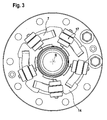
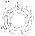
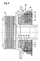
- FIGS. 2 to 4 A preferred embodiment of the present invention is shown in FIGS. 2 to 4, wherein the reference numerals used in the figures are predominantly used for functionally identical components.
- the release levers 7 are distributed tangentially around the circumference and around the rotation axis R evenly spaced around.
- the uniform distribution should be provided in order to obtain a uniform force distribution at the circumference.
- a running unit 17, which consists of three rollers in the preferred embodiment shown, advantageously travels on a circular path over the release lever 7. It is particularly advantageous if the roller which makes contact with the release lever 7 is profiled arcuately on the circumference , as can be clearly seen in Figure 2. Thus, a punctiform contact is made to the release lever 7, which creates a Hertzian pressure contact. By this point contact a third, movable pivot point 10 is provided on the release lever 7.
- the running unit 17 can follow an arcuate travel of the roller over the release lever 7, wherein a small proportion of drilling friction occurs.
- the running units 17 are preferably mounted in a common bearing cage 16, so that by rotation of the bearing cage 16 all running units 17 can be moved together.
- the actuation of the release lever 7 takes place by turning the bearing cage 16, in which the running units 17 are received.
- a spring force is applied by a plate spring 5 via an intermediate plate 18 with cam 19 on one side or one end of the release lever 7, as can be clearly seen in Figure 2.
- the other end of the release lever 7 is rotatably supported by a pin on a lever carrier 14. There then arises the lever rotation axis B, as shown in the figure 4.
- the lever carrier 14 is supported in part and in sections on a pressure plate 15 via a support 22, so that the contact pressure by turning the bearing cage 16 and So that displacement of the support point or pivot point 10 of the rollers of the running unit 17 is changed continuously on the lever.
- the energy from the plate spring 5 is used to actuate the clutch.
- five running units 17 are used for the displacement of the third support point, each consisting of three rollers, which are mounted in a common bearing cage 16.
- a roller - in Figures 2 to 4 the roller with the largest diameter - runs on the release lever 7, while the other two rollers, which are arranged on both sides of the largest role, are supported on the bearing sleeve 20.
- rollers thereby transfer the entire support force over their bearings, which can be seen in the figure 2 in a broken-away partial sectional view.
- a wear adjustment is carried out in the embodiment shown by turning the bearing sleeve 20, against a base flange and an adjusting thread 21, which is preferably designed as a fine thread. The movement is transmitted by a stop between the bearing cage 16 and the lever carrier 14 in the zero position.
- FIG. 4 the direction of rotation A for the engagement is shown in a plan view; the running unit (s) 17 are displaced in the direction of the arrow A, so that the release lever 7 can be pivoted about the lever rotation axis B.
- FIG. 5 again shows a basic structure of a lever system for actuating a clutch or a transmission brake according to the second embodiment, wherein the clutch actuating device shown there can be installed within a short cylindrical installation space.
- a roller system 13 is supported on a support 8, for example a housing of the clutch, which preferably has an energy store 9 in the form of a spring.
- the one end of a lever arm 7a of a disengagement lever (in the top of FIG. 5) is also supported on the support 8.
- the roller system 13 is displaceable such that a pivot point 10 along the lever arm 7a can be moved, as shown in the two representations of Figure 5.
- FIG. 5 again shows a basic structure of a lever system for actuating a clutch or a transmission brake according to the second embodiment, wherein the clutch actuating device shown there can be installed within a short cylindrical installation space.
- a roller system 13 is supported on a support 8, for example a housing of the clutch, which preferably has an energy store 9 in the form of
- the roller system 13 is located at the upper end of the lever arm 7a, so that the pivot point 10 coincides or aligns with the support point on the support 8, whereas in the right-hand illustration of FIG is moved down.
- the clutch is actuated by means of the energy storage 9 a force acting on the lever arm 7a, which is introduced at the lower end, at a support point 12 in the recorded from the bearing shell 26 thrust bearing 11 of the release spring 5.
- the release spring or disc spring 5 then also presses axially on the pressure plate 4, so that the clutch disc 3 between the pressure plate 4 and the counter-pressure plate 2 is held accordingly.
- the release spring 5 is mounted on a clutch cover 6.
- the roller system 13 runs along the support 8. By shifting the pivot point 10 by the roller system 13 is moved, the effective Hebelarmin be changed on both sides of the pivot point 10 on the lever arm 7a, so that in this way the translation of the spring force, the is introduced via the energy storage 9, on the clutch actuation force acting on the thrust bearing 11, is variable.
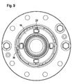
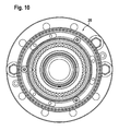
- FIGS. 6 to 10 the reference symbols used in the figures are again used essentially for functionally identical components.
- a particular advantage of the second embodiment is that all components used for contact pressure are arranged axially one behind the other. As a result, the space required in the radial direction is reduced.
- each release lever 7 only one roller 25 is used, which is guided in a two-part bearing cage 16.
- an axial bearing 11 is additionally provided, which is designed as an axial ball bearing.
- a space-saving arrangement can be selected when a ball race is provided directly between a support plate and the plate spring 5. For this purpose, a corresponding career is impressed in the plate spring.
- a plate spring package can also be installed.
- the release lever 7 is mounted with its axis of rotation 24 in the lever carrier 14, which directly to the main body via an adjusting thread 21st connected is.
- the Nachstellgewinde 21 is used for wear adjustment, as in the first embodiment.
- the second bearing axis on the release lever 7 is determined by a cam 19 in the pressure plate 15.
- the third, the (force) translation determining support point is formed by the roller 25.
- a punctiform contact is provided, since the axes of rotation of the release lever 7 and the roller 25 fall apart and are parallel only in one position. For this reason, the roller 25 is also profiled, with respect to the occurring drilling friction is to select a smallest possible profiling radius.
- the illustrated second embodiment it can be represented that the smallest possible normal force acts on the roller 25.
- the second support point, the cam 19 is placed on the pressure plate 15 as close as possible to the pivot point of the release lever 7. In the example shown, this distance is 15 mm. Since the release lever length is a total of 35 mm, can be driven with the roller 25 over this second edition or support point out, so that there is a power gain by about a factor of 2.5. Thus, the plate spring force and thus the normal force can be kept small on the roller 25.
- a dual planetary gearset 28, consisting of a first ring gear 33, a first sun gear 35 and a first planetary gear 34, and a second ring gear 30, a second sun gear 32 and a second planetary gear 31 is provided to form a rotational decoupling to minimize friction losses.
- a ring gear 33 is supported on the housing, while the second ring gear 30 is rotated by an electric motor at 29 (drive), whereby the bearing cage 16 against the lever 7 from the back is rotated.
- the release lever 7 is pivoted and actuated, which in turn pass on the introduced through the plate spring 5 force to the clutch (not shown).
- An end ring 27 is firmly welded.
- FIG 7 is a plan view of the clutch actuating device according to the invention is shown, wherein a release lever 7 has been omitted in order to represent the underlying structure of the lever carrier 14 and (support) cam 19 can.
- the release lever 7 rotates about the axis of rotation 24 and the roller 25 runs on the tangentially arranged release lever 7 preferably on a circular path.
- a stop 36 can be seen, which is provided by a bent tab in the bearing cage 16 for the wear adjustment.
- the top view according to FIG. 10 finally shows the planetary gear set 28, as already described in connection with FIG.
- the rotational decoupling by means of a double planetary gear set is preferably provided in order to reduce losses on the otherwise required thrust bearings.
- a ring gear is supported on the housing, while the second ring gear is rotated by an electric motor, whereby the bearing cage 16 is rotated relative to the release levers 7.
- the release lever 7 are actuated, which in turn pass the force introduced to the clutch.
- the clutch actuating device according to the invention can be used in an all-wheel wet clutch, preferably in a rear differential for distributing the driving forces between the two sides of a motor vehicle or in a longitudinal differential for distributing the driving forces between a rear axle and a front axle.
- the present invention provides a clutch actuating device, in particular for actuating a clutch or a transmission brake of a vehicle, having at least one spring whose spring force for actuating the clutch by means of an associated mechanical power transmission path is transferable to the clutch, wherein the power transmission path at least one comprises displaceable power transmission element, which is designed as a tangential to a rotational axis of the clutch mounted release lever.
- the power transmission path at least one comprises displaceable power transmission element, which is designed as a tangential to a rotational axis of the clutch mounted release lever.
- several power transmission elements are distributed uniformly over the circumference and provided fourfold to eightfold.
Landscapes
- Engineering & Computer Science (AREA)
- General Engineering & Computer Science (AREA)
- Mechanical Engineering (AREA)
- Physics & Mathematics (AREA)
- Electromagnetism (AREA)
- Mechanical Operated Clutches (AREA)
- Braking Arrangements (AREA)
Applications Claiming Priority (1)
| Application Number | Priority Date | Filing Date | Title |
|---|---|---|---|
| DE102005027611 | 2005-06-15 |
Publications (2)
| Publication Number | Publication Date |
|---|---|
| EP1734273A2 true EP1734273A2 (fr) | 2006-12-20 |
| EP1734273A3 EP1734273A3 (fr) | 2009-11-11 |
Family
ID=36956061
Family Applications (1)
| Application Number | Title | Priority Date | Filing Date |
|---|---|---|---|
| EP06009818A Withdrawn EP1734273A3 (fr) | 2005-06-15 | 2006-05-12 | Dispositif de commande pour un embrayage |
Country Status (2)
| Country | Link |
|---|---|
| EP (1) | EP1734273A3 (fr) |
| JP (1) | JP5076089B2 (fr) |
Cited By (5)
| Publication number | Priority date | Publication date | Assignee | Title |
|---|---|---|---|---|
| EP1775494A1 (fr) * | 2005-10-15 | 2007-04-18 | LuK Lamellen und Kupplungsbau Beteiligungs KG | Actionneur de frein |
| EP1832771A1 (fr) * | 2006-03-07 | 2007-09-12 | LuK Lamellen und Kupplungsbau Beteiligungs KG | Actionneur de levier à ressort doté d'un dispositif de réglage |
| CN101457799B (zh) * | 2007-12-13 | 2013-04-17 | 卢克摩擦片和离合器两合公司 | 用于离合器的分离装置 |
| US20130292224A1 (en) * | 2012-05-07 | 2013-11-07 | Hyundai Motor Company | Clutch actuator for a vehicle |
| CN108425961A (zh) * | 2018-05-03 | 2018-08-21 | 泰安泰山国泰拖拉机制造有限公司 | 用于农业机械的挡位离合器装置 |
Families Citing this family (2)
| Publication number | Priority date | Publication date | Assignee | Title |
|---|---|---|---|---|
| JP5272089B1 (ja) * | 2012-03-09 | 2013-08-28 | 株式会社エクセディ | モータサイクル用クラッチ装置 |
| KR101417417B1 (ko) * | 2012-11-20 | 2014-07-08 | 현대자동차주식회사 | 차량용 클러치 액추에이터 |
Family Cites Families (5)
| Publication number | Priority date | Publication date | Assignee | Title |
|---|---|---|---|---|
| JPH11247883A (ja) * | 1998-03-05 | 1999-09-14 | Honda Motor Co Ltd | クラッチリフターカムプレート |
| JP3426524B2 (ja) * | 1999-02-01 | 2003-07-14 | 本田技研工業株式会社 | クラッチレリーズ機構 |
| JP2001132779A (ja) * | 1999-11-02 | 2001-05-18 | Daihatsu Motor Co Ltd | 自動クラッチ装置 |
| DE102004009832A1 (de) * | 2003-03-03 | 2004-09-16 | Luk Lamellen Und Kupplungsbau Beteiligungs Kg | Ausrücksysteme |
| US7147093B2 (en) * | 2003-06-30 | 2006-12-12 | Zf Sachs Ag | Centrifugal clutch |
-
2006
- 2006-05-12 EP EP06009818A patent/EP1734273A3/fr not_active Withdrawn
- 2006-06-14 JP JP2006164533A patent/JP5076089B2/ja not_active Expired - Fee Related
Cited By (8)
| Publication number | Priority date | Publication date | Assignee | Title |
|---|---|---|---|---|
| EP1775494A1 (fr) * | 2005-10-15 | 2007-04-18 | LuK Lamellen und Kupplungsbau Beteiligungs KG | Actionneur de frein |
| EP1992833A3 (fr) * | 2005-10-15 | 2008-11-26 | LuK Lamellen und Kupplungsbau Beteiligungs KG | Dispositif d'actionnement de frein |
| EP1832771A1 (fr) * | 2006-03-07 | 2007-09-12 | LuK Lamellen und Kupplungsbau Beteiligungs KG | Actionneur de levier à ressort doté d'un dispositif de réglage |
| CN101457799B (zh) * | 2007-12-13 | 2013-04-17 | 卢克摩擦片和离合器两合公司 | 用于离合器的分离装置 |
| US20130292224A1 (en) * | 2012-05-07 | 2013-11-07 | Hyundai Motor Company | Clutch actuator for a vehicle |
| US8887885B2 (en) * | 2012-05-07 | 2014-11-18 | Hyundai Motor Company | Clutch actuator for a vehicle |
| CN108425961A (zh) * | 2018-05-03 | 2018-08-21 | 泰安泰山国泰拖拉机制造有限公司 | 用于农业机械的挡位离合器装置 |
| CN108425961B (zh) * | 2018-05-03 | 2024-01-05 | 泰安泰山国泰拖拉机制造有限公司 | 用于农业机械的挡位离合器装置 |
Also Published As
| Publication number | Publication date |
|---|---|
| JP2006349175A (ja) | 2006-12-28 |
| EP1734273A3 (fr) | 2009-11-11 |
| JP5076089B2 (ja) | 2012-11-21 |
Similar Documents
| Publication | Publication Date | Title |
|---|---|---|
| DE102008006024B4 (de) | Freilaufkupplung | |
| DE112011103541B4 (de) | Elektrischer Linearbewegungsaktuator und elektrisches Scheibenbremssystem | |
| DE10392252B4 (de) | Scheibenbremse | |
| DE10112570B4 (de) | Elektrisch betätigbare Scheibenbremse | |
| EP3622194A1 (fr) | Actionneur de frein électromécanique | |
| EP1047874A1 (fr) | Moteur electrique avec engrenage | |
| EP1455106A1 (fr) | Systéme de débrayage | |
| DE102011080498A1 (de) | Parksperre | |
| DE102022120333B4 (de) | Elektromechanische bremse und fahrzeug, das diese umfasst | |
| DE60000438T2 (de) | Getriebeeinheit mit stufenloser drehzahländerung | |
| DE2817389A1 (de) | Mechanische bremsbetaetigungsvorrichtung | |
| EP1963700B1 (fr) | Frein a tambour | |
| DE102014226120A1 (de) | Kennungswandler mit Kurvenscheibe und Lagerpendel zur Betätigung einer Kupplung | |
| WO2007134563A1 (fr) | Système de levier pour l'actionnement d'un embrayage | |
| DE102023115292A1 (de) | Aktor zur Bereitstellung eines Drehmoments mit einem Linearantrieb | |
| DE102006012440A1 (de) | Bremse mit Spindel und Kurvenscheiben-Anordnung | |
| DE2703972A1 (de) | Freilaufeinrichtung | |
| DE10317949B4 (de) | Elektrisch betätigte Bremsanordnung für ein Getriebe | |
| DE102014214137A1 (de) | Betätigungseinrichtung für eine Reibungskupplungsreinrichtung und Reibungskupplungseinrichtung mit einer Betätigungseinrichtung | |
| DE102013215849A1 (de) | Antriebswandlervorrichtung und Achsgetriebevorrichtung mit einer Antriebswandlervorrichtung | |
| DE102005021460A1 (de) | Verstelleinrichtung für Kupplungen und Getriebebremsen, insbesondere von Kraftfahrzeugen zum Verstellen eines einen Auflage- und Drehpunkt eines gebogenen Hebels bildenden Auflagerelements | |
| DE102006022187A1 (de) | Vorrichtung zur Betätigung einer Kupplung | |
| DE112007002890T5 (de) | Lenkvorrichtung mit einer Kugelumlaufspindel | |
| DE102008011338A1 (de) | Automatisches Schaltgetriebe mit abbremsbarer Planeteneinheit | |
| EP3927997B1 (fr) | Entraînement à vis à billes avec dispositif d'antirotation |
Legal Events
| Date | Code | Title | Description |
|---|---|---|---|
| PUAI | Public reference made under article 153(3) epc to a published international application that has entered the european phase |
Free format text: ORIGINAL CODE: 0009012 |
|
| AK | Designated contracting states |
Kind code of ref document: A2 Designated state(s): AT BE BG CH CY CZ DE DK EE ES FI FR GB GR HU IE IS IT LI LT LU LV MC NL PL PT RO SE SI SK TR |
|
| AX | Request for extension of the european patent |
Extension state: AL BA HR MK YU |
|
| PUAL | Search report despatched |
Free format text: ORIGINAL CODE: 0009013 |
|
| AK | Designated contracting states |
Kind code of ref document: A3 Designated state(s): AT BE BG CH CY CZ DE DK EE ES FI FR GB GR HU IE IS IT LI LT LU LV MC NL PL PT RO SE SI SK TR |
|
| AX | Request for extension of the european patent |
Extension state: AL BA HR MK YU |
|
| STAA | Information on the status of an ep patent application or granted ep patent |
Free format text: STATUS: THE APPLICATION IS DEEMED TO BE WITHDRAWN |
|
| 18D | Application deemed to be withdrawn |
Effective date: 20091201 |
|
| P01 | Opt-out of the competence of the unified patent court (upc) registered |
Effective date: 20230519 |