EP1734372A1 - Entraînement pour actionner un battant mobile, particulièrement pour une porte - Google Patents
Entraînement pour actionner un battant mobile, particulièrement pour une porte Download PDFInfo
- Publication number
- EP1734372A1 EP1734372A1 EP06115432A EP06115432A EP1734372A1 EP 1734372 A1 EP1734372 A1 EP 1734372A1 EP 06115432 A EP06115432 A EP 06115432A EP 06115432 A EP06115432 A EP 06115432A EP 1734372 A1 EP1734372 A1 EP 1734372A1
- Authority
- EP
- European Patent Office
- Prior art keywords
- circuit
- control device
- motor
- output
- drive according
- Prior art date
- Legal status (The legal status is an assumption and is not a legal conclusion. Google has not performed a legal analysis and makes no representation as to the accuracy of the status listed.)
- Withdrawn
Links
- 125000004122 cyclic group Chemical group 0.000 claims abstract description 6
- 238000001514 detection method Methods 0.000 claims abstract description 5
- 230000033001 locomotion Effects 0.000 claims description 12
- 239000003990 capacitor Substances 0.000 claims description 7
- 230000005540 biological transmission Effects 0.000 claims description 2
- 230000000903 blocking effect Effects 0.000 description 8
- 230000001419 dependent effect Effects 0.000 description 8
- 230000000694 effects Effects 0.000 description 6
- 230000007257 malfunction Effects 0.000 description 3
- 238000004146 energy storage Methods 0.000 description 2
- 230000001172 regenerating effect Effects 0.000 description 1
- 238000004804 winding Methods 0.000 description 1
Images


Classifications
-
- H—ELECTRICITY
- H02—GENERATION; CONVERSION OR DISTRIBUTION OF ELECTRIC POWER
- H02P—CONTROL OR REGULATION OF ELECTRIC MOTORS, ELECTRIC GENERATORS OR DYNAMO-ELECTRIC CONVERTERS; CONTROLLING TRANSFORMERS, REACTORS OR CHOKE COILS
- H02P3/00—Arrangements for stopping or slowing electric motors, generators, or dynamo-electric converters
- H02P3/06—Arrangements for stopping or slowing electric motors, generators, or dynamo-electric converters for stopping or slowing an individual dynamo-electric motor or dynamo-electric converter
- H02P3/08—Arrangements for stopping or slowing electric motors, generators, or dynamo-electric converters for stopping or slowing an individual dynamo-electric motor or dynamo-electric converter for stopping or slowing a DC motor
- H02P3/12—Arrangements for stopping or slowing electric motors, generators, or dynamo-electric converters for stopping or slowing an individual dynamo-electric motor or dynamo-electric converter for stopping or slowing a DC motor by short-circuit or resistive braking
-
- E—FIXED CONSTRUCTIONS
- E05—LOCKS; KEYS; WINDOW OR DOOR FITTINGS; SAFES
- E05F—DEVICES FOR MOVING WINGS INTO OPEN OR CLOSED POSITION; CHECKS FOR WINGS; WING FITTINGS NOT OTHERWISE PROVIDED FOR, CONCERNED WITH THE FUNCTIONING OF THE WING
- E05F15/00—Power-operated mechanisms for wings
- E05F15/60—Power-operated mechanisms for wings using electrical actuators
- E05F15/603—Power-operated mechanisms for wings using electrical actuators using rotary electromotors
-
- G—PHYSICS
- G01—MEASURING; TESTING
- G01R—MEASURING ELECTRIC VARIABLES; MEASURING MAGNETIC VARIABLES
- G01R31/00—Arrangements for testing electric properties; Arrangements for locating electric faults; Arrangements for electrical testing characterised by what is being tested not provided for elsewhere
- G01R31/34—Testing dynamo-electric machines
- G01R31/346—Testing of armature or field windings
-
- G—PHYSICS
- G01—MEASURING; TESTING
- G01R—MEASURING ELECTRIC VARIABLES; MEASURING MAGNETIC VARIABLES
- G01R31/00—Arrangements for testing electric properties; Arrangements for locating electric faults; Arrangements for electrical testing characterised by what is being tested not provided for elsewhere
- G01R31/50—Testing of electric apparatus, lines, cables or components for short-circuits, continuity, leakage current or incorrect line connections
- G01R31/52—Testing for short-circuits, leakage current or ground faults
-
- G—PHYSICS
- G01—MEASURING; TESTING
- G01R—MEASURING ELECTRIC VARIABLES; MEASURING MAGNETIC VARIABLES
- G01R31/00—Arrangements for testing electric properties; Arrangements for locating electric faults; Arrangements for electrical testing characterised by what is being tested not provided for elsewhere
- G01R31/50—Testing of electric apparatus, lines, cables or components for short-circuits, continuity, leakage current or incorrect line connections
- G01R31/54—Testing for continuity
-
- E—FIXED CONSTRUCTIONS
- E05—LOCKS; KEYS; WINDOW OR DOOR FITTINGS; SAFES
- E05F—DEVICES FOR MOVING WINGS INTO OPEN OR CLOSED POSITION; CHECKS FOR WINGS; WING FITTINGS NOT OTHERWISE PROVIDED FOR, CONCERNED WITH THE FUNCTIONING OF THE WING
- E05F15/00—Power-operated mechanisms for wings
- E05F15/40—Safety devices, e.g. detection of obstructions or end positions
-
- E—FIXED CONSTRUCTIONS
- E05—LOCKS; KEYS; WINDOW OR DOOR FITTINGS; SAFES
- E05F—DEVICES FOR MOVING WINGS INTO OPEN OR CLOSED POSITION; CHECKS FOR WINGS; WING FITTINGS NOT OTHERWISE PROVIDED FOR, CONCERNED WITH THE FUNCTIONING OF THE WING
- E05F15/00—Power-operated mechanisms for wings
- E05F15/70—Power-operated mechanisms for wings with automatic actuation
-
- E—FIXED CONSTRUCTIONS
- E05—LOCKS; KEYS; WINDOW OR DOOR FITTINGS; SAFES
- E05Y—INDEXING SCHEME ASSOCIATED WITH SUBCLASSES E05D AND E05F, RELATING TO CONSTRUCTION ELEMENTS, ELECTRIC CONTROL, POWER SUPPLY, POWER SIGNAL OR TRANSMISSION, USER INTERFACES, MOUNTING OR COUPLING, DETAILS, ACCESSORIES, AUXILIARY OPERATIONS NOT OTHERWISE PROVIDED FOR, APPLICATION THEREOF
- E05Y2400/00—Electronic control; Electrical power; Power supply; Power or signal transmission; User interfaces
- E05Y2400/10—Electronic control
- E05Y2400/30—Electronic control of motors
- E05Y2400/302—Electronic control of motors during electric motor braking
-
- E—FIXED CONSTRUCTIONS
- E05—LOCKS; KEYS; WINDOW OR DOOR FITTINGS; SAFES
- E05Y—INDEXING SCHEME ASSOCIATED WITH SUBCLASSES E05D AND E05F, RELATING TO CONSTRUCTION ELEMENTS, ELECTRIC CONTROL, POWER SUPPLY, POWER SIGNAL OR TRANSMISSION, USER INTERFACES, MOUNTING OR COUPLING, DETAILS, ACCESSORIES, AUXILIARY OPERATIONS NOT OTHERWISE PROVIDED FOR, APPLICATION THEREOF
- E05Y2900/00—Application of doors, windows, wings or fittings thereof
- E05Y2900/10—Application of doors, windows, wings or fittings thereof for buildings or parts thereof
- E05Y2900/13—Type of wing
- E05Y2900/132—Doors
Definitions
- the invention relates to a drive for actuating a movable wing, in particular a door, according to the preamble of patent claim 1.
- a drive for actuating a movable pivoting wing of a door The output member of an electric motor arranged in a motor circuit is operatively connected to the vane via a power transmission device, so that a movement of the output member causes the vane to move.
- a mechanical spring device ensures the closure of the wing in case of failure of the electrical power supply.
- a braking device is provided by the electric motor is operated as a generator. The output voltage of the generator-operated electric motor is applied to an arranged in a brake circuit, electrical resistance.
- the electric motor is short-circuited for this purpose, so that the output voltage of the generator-operated electric motor is applied to a low ohmic resistance. If there is an interruption of the motor circuit or the braking circuit, the generator-operated electric motor is no longer connected to the resistor, so that the braking device is ineffective. An interruption of the motor windings can lead to failure of the braking device.
- the control device of the drive described in the publication does not detect such disturbances.
- the invention has for its object to further develop a generic drive so that disturbances of the motor circuit and the brake circuit can be detected.
- the control device of the drive is designed so that cyclic tests of the motor circuit and the brake circuit can be carried out, wherein upon detection of a fault of the motor circuit or the brake circuit, a safety reaction takes place.
- a safety reaction takes place upon detection of a fault of the motor circuit or the brake circuit.
- the control device may have a test signal input for a test signal that can be generated when testing the motor circuit or the braking circuit.
- the control device Since the control device has an output for driving the electric motor, the output signal of this output can be used to test the motor circuit or brake circuit, so that no further, separate output of the control device is required for the test signal.
- the brake circuit has a switching device, by which the motor circuit with the brake circuit is electrically connectable or decoupled from this.
- a simply constructed and at the same time reliable switching device can be achieved by having a relay with a relay contact.
- the control device may have an output.
- the brake circuit may have a further switch device designed as a switch, by which the current direction in the brake circuit can be switched. In addition to a reversal of the direction of current flow in the brake circuit This switch device also enables the generation of various test circuits within the brake circuit.
- the brake circuit may comprise a voltage divider formed from two resistors connected in series.
- the voltage divider may for example be arranged between a point of the braking circuit and the ground potential.
- the test signal input of the control device may be connected to the center tap of the voltage divider.
- potentials can be detected at specific points of the brake circuit by means of the voltage divider and converted into a signal detectable for the test signal input of the control device.
- Parallel to the resistor of the voltage divider arranged between the center tap and the ground potential, a capacitor can be arranged which serves to smooth the voltage which can be tapped off here.
- the output shaft of the electric motor or a motion connected to the output shaft of the electric motor part of the drive may be connected to a braking device.
- the control device may have an output for controlling the braking device.
- the braking device ensures that movements of the output shaft of the electric motor and thus of the connected wing can be safely braked and possibly blocked, in particular in the detection of safety-relevant faults or in the performance of the cyclic tests.
- the output shaft of the electric motor can be connected to an encoder device, wherein the control device can have an input for a signal of the encoder device.
- control device can have an input for a signal which indicates the current flowing through the electric motor.
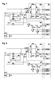
- Fig. 1 shows a circuit arrangement of the drive in a first operating state.
- the components of the circuit arrangement are shown summarized with dashed frames to form units: A motor unit ME, a motor circuit MS, a control device SE and a brake circuit BS.
- a motor unit ME motor unit
- MS motor circuit
- SE brake circuit
- BS brake circuit
- the control device SE has an output A-PWM for outputting a pulse width modulated signal.
- This is the motor circuit MS, which has, inter alia, a bridge rectifier BG and a transistor bridge supplied.
- the output terminals A-MS1, A-MS2 of the motor circuit MS are connected to relay contacts K1.1, K2.1 of the brake circuit BS.
- the relay contacts K1.1, K2.1 can be switched by the relays K1, K2 between two switch positions A, B, C, D respectively.
- the switching coils of the relays K1, K2 are, in each case connected in series with the drain-source path of a transistor T1, T2, connected between an operating voltage U B and the ground potential.
- the gate terminals of the transistors T1, T2 are each connected to an output A-K1, A-K2 of the control device SE.
- the transistors T1, T2 are each blocking, so that the switching coils of the relay K1, K2 are not current-carrying and the relay contacts K1.1, K2.1 in the lower in the drawing Switch positions B, D are located.
- the drain-source path of the respective transistor T1, T2 is conductive, which energization of the switching coil of the respective relay K1, K2 and thus switching the respective Relay contacts K1.1, K2.1 of the one switching position B, D causes the second switching position A, C.
- the motor unit ME comprises an electric motor M, which is arranged in the motor circuit and designed as a direct-current motor, whose rotational speed can be detected by an encoder device IG.
- the output signal of the rotary encoder device IG which may be embodied as an incremental encoder, for example, is fed to the input E-IG of the control device SE, so that in the control device SE, the speed of the electric motor and stored drive parameters and the position of the connected wing can be detected.
- the motor unit ME also comprises a mechanical braking device MB, which is coupled to an output shaft of the electric motor M.
- the braking device MB may be formed as a magnetic brake, wherein the coil of the electromagnet is connected in series with the drain-source path of a transistor T3 between an operating voltage U B and the ground potential.
- the gate terminal of the transistor T3 is connected to an output A-MB of the control device SE. If there is no signal of the output A-MB, the transistor T3 is blocking, so that the coil of the magnetic brake is not current-carrying and therefore the brake has no braking effect.
- the drain-source path of the transistor T3 In the presence of an output signal of the output A-MB of the control device SE, the drain-source path of the transistor T3 is conductive, which causes an energization of the coil of the magnetic brake and thus the braking effect on the electric motor M.
- the brake circuit BS has a brake circuit which is connected to the electric motor M at the lower positions B, D of the relay contacts K1.1, K2.1 of the relays K1, K2 in the drawing.
- a series circuit of a diode D1 and a braking resistor RB is arranged in the brake circuit.
- the braking resistor RB is the load resistance for the generator-driven electric motor M.
- the diode D1 causes the braking circuit is effective only in one direction. The function of the brake circuit is thus dependent on the polarity of the voltage applied to it.
- the selected representation with diode D1 and braking resistor RB is representative of all the brake circuits with polarity dependent function, i. There are also deviating components with polarity-dependent behavior in the brake circuit conceivable.
- F switch device S1 is arranged, through which the polarity of the voltage applied to the brake circuit voltage can be switched, so that the brake circuit for both directions of rotation of the generator-operated electric motor can be effectively switched.
- two test voltage taps are also present in the brake circuit BS. These are formed by voltage dividers, which each consist of two series-connected, high-resistance resistors R1, R2, R3, R4. The voltage dividers are each connected between the ground potential and a reference point of the braking circuit, wherein the reference point of the first, left in the drawing voltage divider on one side of the series formed by the diode D1 and the braking resistor RB series circuit and the reference point of the second, in the drawing right voltage divider on the other side.
- the center tap located between the resistors R1, R2 of the first voltage divider is connected to a test signal input E-TS1 of the control device SE.
- a capacitor C1 arranged between the test signal input E-TS1 and the ground potential smoothes the test voltage applied to the test signal input E-TS1.
- the center tap located between the resistors R3, R4 of the second voltage divider is connected to a further test signal input E-TS2 of the control device SE, wherein a capacitor C2 arranged between the test signal input E-TS2 and the ground potential blocks the test voltage applied to the test signal input E-TS2 smoothes.
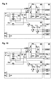
- the circuit arrangement is shown in a second operating state of the drive.
- the outputs A-K1, A-K2 of the control device SE are each inactive, so that the transistors T1, T2 blocking and the switching coils of the relays K1, K2 are not current-carrying.
- the relay contacts K1.1, K2.1 of the relays K1, K2 are thus in the lower switching positions B, D in the drawing, so that the electric motor M is connected to the braking circuit of the brake circuit BS.
- the electric motor M is operated as a generator and induces a voltage whose height and polarity of the rotational speed and direction of rotation of the electric motor M is dependent.
- the motor voltage is in the illustrated operating state of the brake circuit located in the series circuit of the diode D1 and the braking resistor RB.
- the braking current in the braking circuit is thus dependent on the direction of rotation and the rotational speed of the generator-operated electric motor M and on the parameters of the diode D1 and the braking resistor RB.
- the brake circuit is to be effective also in the other regenerative direction of rotation of the electric motor M, the brake circuit is reversed by switching over from the illustrated switching position F to the other switching position E by means of the switch device S1.
- FIG. 3 shows an operating state of the circuit arrangement of the drive containing a first test step.
- the control device SE activates the mechanical braking device via an output signal of its output A-MB MB, so that the electric motor M is blocked in its current position.
- the control device SE outputs a signal to the motor circuit MS, which causes a positive potential located at the upper output A-MS1 of the motor circuit MS in the drawing.
- the control device SE controls via its output A-K1 left in the drawing relay K1, so that this occupies its illustrated switching position A.
- the right in the drawing right relay K2 output A-K2 of the control device SE is inactive, so that this relay K2 assumes the switching position D shown.
- the positive potential located at the upper output A-MS1 of the motor circuit MS in the drawing is thus connected to the ground potential via the electric motor M, the switching device located in switch position F and the series connection of the resistors R3, R4 of the right-hand voltage divider in the drawing a positive voltage is present at the center tap of the voltage divider (referred to below as "high signal") which is detected by the control device SE by means of its second test signal input E-TS2.
- the first test step shown in FIG. 3 thus relates, independently of the brake circuit, solely to the motor circuit.
- a positive result i. High signal at the second test signal input E-TS2, low signal at the first test signal input E-TS1 of the control device SE, thus means that the motor circuit is faultless.
- the operating state of the circuit arrangement of the drive shown in FIG. 4 involves the brake circuit in the test. That of the output signal A-PWM of the controller SE for the motor circuit MS dependent potential at the upper in the drawing output A-MS1 of the motor circuit MS corresponds to that of the test step previously described in Fig. 3, ie it is positive.
- the position of the relay contacts K1.1, K2.1 of the two relays K1, K2, which depends on the signals of the outputs A-K1, A-K2 of the control device SE, corresponds to that of the test step described above in FIG.
- the positive potential located at the upper output A-MS1 of the motor circuit MS in the drawing is thus connected to the ground potential via the electric motor M, the switching device located in switching position E and the series connection of the resistors R1, R2 of the left-hand voltage divider in the drawing a high signal is present at the center tap of the voltage divider, which is detected by the control device SE by means of its first test signal input E-TS1.
- the at the upper in the drawing output A-MS1 of the motor circuit MS positive potential is also on the electric motor M, located in switching position E switching device, the conductive diode D1, the braking resistor RB and the series connection of the resistors R3, R4 of in the Drawing right voltage divider placed against the ground potential, so that even at the center tap of this voltage divider a high signal is present, which is detected by the control device SE by means of its first test signal input E-TS2.
- the second test step shown in FIG. 4 thus relates to the series connection of the motor circuit to the brake circuit.
- the control device SE outputs via its output A-PWM a signal to the motor circuit MS, which is a positive potential located at the lower output A-MS2 of the motor circuit MS in the drawing causes.
- the position of the relays K1, K2 is also changed, i. the output A-K2 of the control device SE assigned to the left-hand relay K2 in the drawing is inactive, so that this relay K2 assumes the switching position B shown.
- the control device SE controls via its output A-K2 the right in the drawing relay K2, so that this occupies its illustrated switching position C.
- the positive potential located at the lower output A-MS2 of the motor circuit MS in the drawing is thus connected to the ground potential via the electric motor M, the switching device located in switch position F and the series connection of the resistors R1, R2 of the left-hand voltage divider in the drawing a high signal is present at the center tap of the voltage divider, which is detected by the control device SE by means of its first test signal input E-TS1.
- the at the lower in the drawing output A-MS2 of the motor circuit MS positive potential is also on the electric motor M, located in switching position F switching device, the conductive diode D1, the braking resistor RB and the series connection of the resistors R3, R4 of in the Drawing right voltage divider placed against the ground potential, so that even at the center tap of this voltage divider a high signal is present, which is detected by the control device SE by means of its first test signal input E-TS2.
- the third test step shown in FIG. 5 thus relates to the series connection of the motor circuit to the brake circuit.
- the operating state of the circuit arrangement illustrated in FIG. 6 comprises a fourth test step.
- the potential dependent on the output signal A-PWM of the control device SE for the motor circuit MS at the lower output A-MS2 of the motor circuit MS in the drawing corresponds to that of the test step described above in FIG. 5, ie it is positive.
- the position of the relay contacts K1.1, K2.1 of the two relays K1, K2, which depends on the signals of the outputs A-K1, A-K2 of the control device SE, corresponds to that of the test step described above in FIG.
- the positive potential located at the lower output A-MS2 of the motor circuit MS in the drawing is thus connected to the ground potential via the electric motor M, the switching device located in switching position E and the series connection of the resistors R3, R4 of the right-hand voltage divider in the drawing a high signal is present at the center tap of the voltage divider, which is detected by the control device SE by means of its second test signal input E-TS2.
- the fourth test step illustrated in FIG. 6 thus relates solely to the motor circuit, independently of the brake circuit.
- a positive result ie high signal at the second test signal input E-TS2 and low signal at the first test signal input E-TS1 of the control device SE, thus means that the motor circuit is error-free even in the second braking direction.
- a fifth test step can be carried out with the circuit arrangement already shown in FIG. 1 and the switch positions A, C of the relay contacts K1.1, K2.1 of the relays K1, K2 and the switch position F of the switch device S1 shown there, in order to improve the functionality of the circuit Motor circuit and the mechanical braking device MB determine.
- the control device SE outputs via its output A-PWM a signal to the motor circuit MS, which causes a corresponding voltage between the outputs A-MS1, A-MS2 of the motor circuit MS.
- the control device SE measures the motor current by means of its input EI Mot . If no motor current is measured, there is a fault, such as interruption of the motor circuit.
- the output A-MB of the control device SE associated with the mechanical braking device MB is active, i.
- the braking device MB is energized via the then conducting transistor T3 and blocks the movement of the electric motor M.
- the control device SE detects the signal of the rotary encoder device IG by means of its input E-IG. This must be zero in this test step with functional braking device MB; otherwise there is a malfunction of the braking device MB.
- FIG. 7 shows a circuit arrangement of the drive deviating from those previously shown in FIGS. 1 to 6 in a first operating state.
- the components of the circuit arrangement are, as in the previously illustrated embodiments, shown in dashed outline to units motor unit ME, motor circuit MS, control device SE and brake circuit BS summarized.
- control device SE the motor circuit MS and the motor unit ME in this case are similar to the previously illustrated and described structural units, so that in this regard reference is made to the description of FIG. Only the brake circuit BS is modified compared to the embodiments already described:
- the output terminal A-MS1 of the motor circuit MS is connected to the relay contacts K1.1, K2.1 of two relays K1, K2 of the brake circuit BS.
- the relay contacts K1.1, K2.1 can be switched by the relays K1, K2 between two switch positions A, B, C, D respectively.
- the switching coils of the relays K1, K2 are, in each case connected in series with the drain-source path of a transistor T1, T2, connected between an operating voltage U B and the ground potential.
- the gate terminals of the transistors T1, T2 are each connected to an output A-K1, A-K2 of the control device SE.
- the transistors T1, T2 are each blocking, so that the switching coils of the relays K1, K2 are not current-carrying.
- the relay contact K1.1 of the left in the drawing relay K1 is then in the lower position in the drawing B, and the relay contact K2.1 of the right in the drawing relay K2 in the right in the drawing position D.
- one or both outputs A-K1, A-K2 of the control device SE is the drain-source path of the respective transistor T1, T2 conductive, which energization of the switching coil of the respective relay K1, K2 and thus switching the respective relay contact K1.1 , K2.1 of the one switching position B, D causes the second switching position A, C.
- the output terminal A-MS2 of the motor circuit MS is directly connected to the arranged in the motor unit ME in the motor circuit, designed as a DC motor electric motor M whose speed is detected by an encoder means IG.
- the output signal of the rotary encoder device IG which For example, can be configured as an incremental encoder, the input E-IG of the control device SE is fed, so that in the control device SE, the speed of the electric motor and stored drive parameters and the position of the connected wing can be detected.
- the motor unit ME also comprises a mechanical braking device MB, which is coupled to an output shaft of the electric motor M.
- the braking device MB may be formed as a magnetic brake, wherein the coil of the electromagnet is connected in series with the drain-source path of a transistor T3 between an operating voltage U B and the ground potential.
- the gate terminal of the transistor T3 is connected to an output A-MB of the control device SE. If there is no signal of the output A-MB, the transistor T3 is blocking, so that the coil of the magnetic brake is not current-carrying and therefore the brake has no braking effect.
- the drain-source path of the transistor T3 In the presence of an output signal of the output A-MB of the control device SE, the drain-source path of the transistor T3 is conductive, which causes an energization of the coil of the magnetic brake and thus the braking effect on the electric motor M.
- the brake circuit BS has a brake circuit, which at the lower in the drawing position B of the relay contact K1.1 of the left in the drawing relay K1 in conjunction with the right in the drawing switching position D of the relay contact K2.1 of the right in the drawing relay K2 is connected to the electric motor M.
- a braking resistor RB is arranged as a load resistor for the generator-operated electric motor M.
- the brake circuit is effective in both current directions, so that an additional switch means for reversing the polarity of the brake circuit is not required.
- a test voltage tap is also present in the brake circuit BS.
- This is formed by a voltage divider, which consists of two series-connected, high-resistance resistors R1, R2.
- the voltage divider is between the ground potential and a reference point the brake circuit is connected, which is located between the braking resistor RB and the relay contact K1.1 of the left in the drawing K1.
- the center tap located between the resistors R1, R2 of the voltage divider is connected to a test signal input E-TS of the control device SE.
- a capacitor C1 arranged between the test signal input E-TS and the ground potential smoothes the test voltage applied to the test signal input E-TS.
- the output A-K1 of the control device SE is active and causes the relay contact K1.1 of the left in the drawing K1 has assumed the upper switching position A in the drawing.
- the electric motor M is thus connected to the output terminals A-MS1, A-MS2 of the motor circuit MS and, depending on the signal of the output A-PWM of the control device SE, can be operated in both directions of rotation.
- the mechanical braking device MB is not active.
- the other components of the brake circuit BS are electrically decoupled from the electric motor M due to the switching position A of the relay contact K1.1 of the relay K1. Tests of the brake circuit BS are not performed in this operating state.
- FIG. 8 the circuit arrangement described above in FIG. 7 is shown in a second operating state of the drive.
- the outputs A-K1, A-K2 of the control device SE are each inactive, so that the transistors T1, T2 blocking and the switching coils of the relays K1, K2 are not current-carrying.
- the relay contacts K1.1, K2.1 of the relays K1, K2 are thus in the left in the drawing, or lower switch positions B, D, so that the electric motor M is connected to the brake circuit of the brake circuit BS.
- the electric motor M If a mechanical movement in the driven member of the electric motor M is initiated, for example by a mechanical energy storage device, the electric motor M is operated as a generator and induces a voltage whose height depends on the speed of the electric motor M.
- the motor voltage is in the illustrated operating state of the braking resistor located in the braking circuit RB.
- the braking current in the brake circuit is thus dependent on the speed of the generator-operated electric motor M and the parameters of the braking resistor RB.
- FIG. 9 shows an operating state of the circuit arrangement of the drive containing a first test step.
- the control device SE activates the mechanical braking device MB via an output signal of its output A-MB, so that the electric motor M is blocked in its current position.
- the control device SE outputs a signal to the motor circuit MS, which causes a voltage applied between the outputs A-MS1, A-MS2 of the motor circuit MS voltage.
- the control device SE controls via its output A-K2 the right in the drawing relay K2, so that this occupies its illustrated switching position C.
- the one in the drawing left relay K1 associated output A-K1 of the control device SE is inactive, so that this relay K1 assumes the switching position B shown.
- the voltage applied between the outputs A-MS1, A-MS2 of the motor circuit MS voltage is thus connected to a series circuit of the braking resistor RB and the electric motor M.
- the current flow through this series circuit is connected via the ground potential switched shunt resistors RS1, RS2 of the motor circuit MS by the Control device SE measured by means of its input EI Mot .
- the parameters of the components ie the internal resistance of the electric motor M, the intermediate circuit voltage of the motor circuit MS, the duty cycle of the signal of the output A-PWM of the control device SE and the maximum value of the braking resistor RB
- can in the control device SE is calculated from the measured current, the actual value of the braking resistor RB and compared with the stored setpoint.
- a safety reaction of the drive takes place, for example, its decommissioning and the generation and possibly emission of an error message.
- a second test step can be carried out with the circuit arrangement already shown in FIG. 7 and the switch positions A, D of the relay contacts K1.1, K2.1 of the relays K1, K2 shown there in order to determine the functionality of the motor circuit and of the mechanical brake device MB ,
- the control device SE outputs via its output A-PWM a signal to the motor circuit MS, which causes a corresponding voltage between the outputs A-MS1, A-MS2 of the motor circuit MS.
- the signal of the output A-PWM of the control device SE is selected such that the upper output A-MS1 of the motor circuit MS in the drawing has a positive potential compared with the lower output A-MS2 of the motor circuit in the drawing and with respect to the ground potential .
- the control device SE measures the motor current by means of its input EI Mot . If no motor current is measured, there is a fault, such as an interruption of the motor circuit.
- the mechanical braking device MB associated output A-MB of the control device SE is active, ie via the then conducting transistor T3, the braking device MB is energized and blocks the movement of the electric motor M.
- the control device SE detected by its input E-IG the signal of the rotary encoder IG. This must be zero in this test step with functional braking device MB; otherwise there is a malfunction of the braking device MB.
- FIG. 7 An operation state of the circuit arrangement of the drive including a third test step is shown in FIG .
- the switching positions A, D of the relay contacts K1.1, K2.1 of the two relays K1, K2 correspond to those of the exemplary embodiments of FIGS. 7 and 9.
- the signal of the output A-PWM of the control device SE is chosen such that the bottom in the drawing output A-MS2 of the motor circuit MS has a relation to the upper in the drawing output A-MS1 of the motor circuit and with respect to the ground potential positive potential.
- the control device SE measures the motor current by means of its input EI Mot . If no motor current is measured, there is a fault, such as an interruption of the motor circuit.
- the output A-MB of the control device SE associated with the mechanical brake device MB is active, i.
- the braking device MB is energized via the then conducting transistor T3 and blocks the movement of the electric motor M.
- the control device SE detects the signal of the rotary encoder device IG by means of its input E-IG. This must be zero in this test step with functional braking device MB; otherwise there is a malfunction of the braking device MB.
Landscapes
- Physics & Mathematics (AREA)
- General Physics & Mathematics (AREA)
- Engineering & Computer Science (AREA)
- Power Engineering (AREA)
- Stopping Of Electric Motors (AREA)
- Control Of Direct Current Motors (AREA)
Applications Claiming Priority (1)
| Application Number | Priority Date | Filing Date | Title |
|---|---|---|---|
| DE102005028058A DE102005028058B3 (de) | 2005-06-16 | 2005-06-16 | Antrieb zum Betätigen eines beweglichen Flügels, insbesondere einer Tür |
Publications (1)
| Publication Number | Publication Date |
|---|---|
| EP1734372A1 true EP1734372A1 (fr) | 2006-12-20 |
Family
ID=36571404
Family Applications (1)
| Application Number | Title | Priority Date | Filing Date |
|---|---|---|---|
| EP06115432A Withdrawn EP1734372A1 (fr) | 2005-06-16 | 2006-06-14 | Entraînement pour actionner un battant mobile, particulièrement pour une porte |
Country Status (2)
| Country | Link |
|---|---|
| EP (1) | EP1734372A1 (fr) |
| DE (1) | DE102005028058B3 (fr) |
Cited By (1)
| Publication number | Priority date | Publication date | Assignee | Title |
|---|---|---|---|---|
| CN110778237A (zh) * | 2019-10-18 | 2020-02-11 | 南京工程学院 | 一种自动关门障碍物类型的分辨方法及自动门控制器 |
Families Citing this family (3)
| Publication number | Priority date | Publication date | Assignee | Title |
|---|---|---|---|---|
| DE102009017114A1 (de) | 2009-04-15 | 2010-10-21 | Dorma Gmbh + Co. Kg | Verfahren zum Betreiben eines Türantriebs bzw. einer automatisierten Türanlage |
| DE102009027239B4 (de) | 2009-06-26 | 2013-08-08 | Geze Gmbh | Türanlage |
| DE102011112273A1 (de) | 2011-09-05 | 2013-03-07 | Brose Fahrzeugteile Gmbh & Co. Kg, Hallstadt | Antriebsanordnung zur motorischen Verstellung eines Verstellelements eines Kraftfahrzeugs |
Citations (6)
| Publication number | Priority date | Publication date | Assignee | Title |
|---|---|---|---|---|
| US4289995A (en) * | 1979-08-01 | 1981-09-15 | Keane Monroe Corporation | Electric door operator with slip clutch and dynamic braking |
| US5018304A (en) * | 1990-05-10 | 1991-05-28 | F. L. Saino Manufacturing Co. | Door operator |
| JPH03218201A (ja) * | 1990-01-24 | 1991-09-25 | Shikoku Seisakusho:Kk | 電動車の故障診断方法 |
| JPH03265401A (ja) * | 1989-12-22 | 1991-11-26 | Shikoku Seisakusho:Kk | 電動車の制御基板点検方法 |
| EP0562153A1 (fr) * | 1992-03-23 | 1993-09-29 | Thomas Industries Inc. | Dispositif de contrôle pour ouverture aisée de porte |
| US5913763A (en) * | 1993-07-19 | 1999-06-22 | Dorma Door Controls, Inc. | Method for controlling the operational modes of a door in conjunction with a mechanical door control mechanism |
Family Cites Families (1)
| Publication number | Priority date | Publication date | Assignee | Title |
|---|---|---|---|---|
| DE4100335C2 (de) * | 1991-01-08 | 1995-11-23 | Tuerautomation Fehraltorf Ag F | Elektromechanischer Drehflügelantrieb für Schwenkflügel von Türen oder dergleichen |
-
2005
- 2005-06-16 DE DE102005028058A patent/DE102005028058B3/de not_active Revoked
-
2006
- 2006-06-14 EP EP06115432A patent/EP1734372A1/fr not_active Withdrawn
Patent Citations (6)
| Publication number | Priority date | Publication date | Assignee | Title |
|---|---|---|---|---|
| US4289995A (en) * | 1979-08-01 | 1981-09-15 | Keane Monroe Corporation | Electric door operator with slip clutch and dynamic braking |
| JPH03265401A (ja) * | 1989-12-22 | 1991-11-26 | Shikoku Seisakusho:Kk | 電動車の制御基板点検方法 |
| JPH03218201A (ja) * | 1990-01-24 | 1991-09-25 | Shikoku Seisakusho:Kk | 電動車の故障診断方法 |
| US5018304A (en) * | 1990-05-10 | 1991-05-28 | F. L. Saino Manufacturing Co. | Door operator |
| EP0562153A1 (fr) * | 1992-03-23 | 1993-09-29 | Thomas Industries Inc. | Dispositif de contrôle pour ouverture aisée de porte |
| US5913763A (en) * | 1993-07-19 | 1999-06-22 | Dorma Door Controls, Inc. | Method for controlling the operational modes of a door in conjunction with a mechanical door control mechanism |
Non-Patent Citations (2)
| Title |
|---|
| PATENT ABSTRACTS OF JAPAN vol. 015, no. 497 (M - 1192) 16 December 1991 (1991-12-16) * |
| PATENT ABSTRACTS OF JAPAN vol. 016, no. 082 (M - 1215) 27 February 1992 (1992-02-27) * |
Cited By (1)
| Publication number | Priority date | Publication date | Assignee | Title |
|---|---|---|---|---|
| CN110778237A (zh) * | 2019-10-18 | 2020-02-11 | 南京工程学院 | 一种自动关门障碍物类型的分辨方法及自动门控制器 |
Also Published As
| Publication number | Publication date |
|---|---|
| DE102005028058B3 (de) | 2006-06-22 |
Similar Documents
| Publication | Publication Date | Title |
|---|---|---|
| DE112016001924B4 (de) | Treibervorrichtung | |
| DE102007059492A1 (de) | Industrieroboter | |
| DE102014204783A1 (de) | Motortreibervorrichtung | |
| EP2313584A1 (fr) | Fermeture de portiere de vehicule a moteur avec une circuiterie | |
| EP3460593A1 (fr) | Dispositif de commutation sécurisé | |
| EP0052759B1 (fr) | Dispositif dans un poste électronique d'aguillage pour l'alimentation et le télécontrôle de la commande d'aiguilles | |
| DE102012111870A1 (de) | Signalausgabeschaltung | |
| WO2012084002A1 (fr) | Circuit de commande pour un relais électromagnétique | |
| EP1941120B1 (fr) | Mecanisme d'entrainement destine a actionner un battant mobile, en particulier une porte | |
| EP1004059B1 (fr) | Procede pour la detection des connexions defectueuses d'un premier relais | |
| DE69702869T2 (de) | Sicherheitsrelais | |
| DE102005028058B3 (de) | Antrieb zum Betätigen eines beweglichen Flügels, insbesondere einer Tür | |
| DE102012219320A1 (de) | Leistungselektronische Schaltung, elektrische Maschine und Verfahren zum Überprüfen der Funktionsfähigkeit einer leistungselektronischen Schaltung | |
| DE102011118488A1 (de) | Motorantrieb für Stufenschalter | |
| DE10108975A1 (de) | Verfahren zur Steuerung eines Elektromotors | |
| EP1444782B1 (fr) | Dispositif de commande d'une charge electrique et appareil de commande | |
| EP2750960B1 (fr) | Moteur électrique ayant une source de courant d'essai | |
| DE3213225C2 (de) | Überwachungs-Schaltungs-Anordnung für die Fahrtrichtungsschützkontakte bei einem umsteuerbaren elektrischen Fahrmotorantrieb | |
| EP2876509B1 (fr) | Commande de sécurité | |
| DE2210747C3 (de) | Überlastungsschutzanordnung für einen impulsgespeisten Gleichstrommotor | |
| DE102018200120A1 (de) | Sicherheitssteuerung mit wenigstens einem Halbleiterschaltkontakt | |
| DE112017002977B4 (de) | Elektronische steuereinheit | |
| EP2269296B1 (fr) | Circuit de controle pour un moteur a courant continu avec un pont en h et un circuit de frein moteur | |
| DE102020107933A1 (de) | Motorsteuerung mit zweikanaliger, die funktionale Sicherheit betreffende Safetorque-off Funktion | |
| EP1244564A1 (fr) | Circuit electrique pour la commande d'un moteur electrique dans un vehicule |
Legal Events
| Date | Code | Title | Description |
|---|---|---|---|
| PUAI | Public reference made under article 153(3) epc to a published international application that has entered the european phase |
Free format text: ORIGINAL CODE: 0009012 |
|
| AK | Designated contracting states |
Kind code of ref document: A1 Designated state(s): AT BE BG CH CY CZ DE DK EE ES FI FR GB GR HU IE IS IT LI LT LU LV MC NL PL PT RO SE SI SK TR |
|
| AX | Request for extension of the european patent |
Extension state: AL BA HR MK YU |
|
| 17P | Request for examination filed |
Effective date: 20070615 |
|
| 17Q | First examination report despatched |
Effective date: 20070726 |
|
| AKX | Designation fees paid |
Designated state(s): AT BE BG CH CY CZ DE DK EE ES FI FR GB GR HU IE IS IT LI LT LU LV MC NL PL PT RO SE SI SK TR |
|
| STAA | Information on the status of an ep patent application or granted ep patent |
Free format text: STATUS: THE APPLICATION HAS BEEN WITHDRAWN |
|
| 18W | Application withdrawn |
Effective date: 20120803 |