EP1734737A1 - Bildverarbeitungsverfahren und Speichermedium für die Lagerung eines Bildverarbeitungsprogramms - Google Patents
Bildverarbeitungsverfahren und Speichermedium für die Lagerung eines Bildverarbeitungsprogramms Download PDFInfo
- Publication number
- EP1734737A1 EP1734737A1 EP06250357A EP06250357A EP1734737A1 EP 1734737 A1 EP1734737 A1 EP 1734737A1 EP 06250357 A EP06250357 A EP 06250357A EP 06250357 A EP06250357 A EP 06250357A EP 1734737 A1 EP1734737 A1 EP 1734737A1
- Authority
- EP
- European Patent Office
- Prior art keywords
- pixel
- contour
- target pixel
- value
- output
- Prior art date
- Legal status (The legal status is an assumption and is not a legal conclusion. Google has not performed a legal analysis and makes no representation as to the accuracy of the status listed.)
- Granted
Links
Images





Classifications
-
- H—ELECTRICITY
- H04—ELECTRIC COMMUNICATION TECHNIQUE
- H04N—PICTORIAL COMMUNICATION, e.g. TELEVISION
- H04N1/00—Scanning, transmission or reproduction of documents or the like, e.g. facsimile transmission; Details thereof
- H04N1/40—Picture signal circuits
- H04N1/409—Edge or detail enhancement; Noise or error suppression
- H04N1/4092—Edge or detail enhancement
-
- H—ELECTRICITY
- H04—ELECTRIC COMMUNICATION TECHNIQUE
- H04N—PICTORIAL COMMUNICATION, e.g. TELEVISION
- H04N1/00—Scanning, transmission or reproduction of documents or the like, e.g. facsimile transmission; Details thereof
- H04N1/40—Picture signal circuits
- H04N1/405—Halftoning, i.e. converting the picture signal of a continuous-tone original into a corresponding signal showing only two levels
Definitions
- This invention relates to an image processing method and a recording medium storing an image processing program and, more particularly, to an image processing method and a recording medium storing image processing program for properly processing contour portions of an object.
- a dot is performed every predetermined number of pixels (a spot formed by using such a screen pattern is referred to as a dot).
- a dither process is performed in such a printer to represent a letter image in a halftone, a phenomenon which is called a jaggy and in which a contour portion (i.e., an outline portion) of the letter looks to be jagged may occur or part of the letter may be thinned, as shown in FIG. 9, because of the difference between the angle of a contour line of the letter image and a screen angle. If such degradation in image quality makes it difficult to identify a contour portion of the letter, the apparent resolution of the letter image lowers, resulting in lower visibility.
- FIG. 10B a dotted line indicates a contour line.
- a dotted line indicates a contour line.
- dots are outputted in some contour portions and are not outputted in others.
- a jaggy phenomenon has occurred.
- a contour portion of a vertical line of "T" thinning has occurred, so the shape of the original letter cannot be reproduced accurately.
- a method for determining the characteristics (indicative of an image type such as a character, a graphic, or a photograph drawing) of each pixel from information described in a page description language (PDL) and for performing image processing according to the characteristics has conventionally been disclosed (see, for example, JP-Tokukai-Hei-9-282471A ).
- a TEXT signal indicative of a letter is generated for a pixel in an image area including, for example, a letter for which importance is attached to resolution.
- a high-resolution screen such as a 400-line single line screen
- a low-resolution screen such as a 200-line single line screen
- the screens which differ in resolution are used in this way for avoiding degradation in the resolution of a letter area.
- the stage of printing out density may differ according to the relative positions of two or more dots formed by ink or toner.
- the total of the toner densities of two dots adjacent to each other may differ from the total of the toner densities of two dots distant from each other due to the frequency response characteristics of a printer. That is to say, when one dot is formed, the printer responds slowly and the amount of toner or the like outputted is small. On the other hand, when two dots are formed in succession, the printer responds quickly and the amount of the toner or the like outputted increases.
- output characteristics differ among different printers in degree.
- the density of a portion in which dots are touching becomes high. If the contour area is studded with high density portions at regular intervals or randomly, then a jaggy appears and image quality may be degraded. Intervals at which dots are touching are long when the screen angle of a single line screen used for performing a dither process on the non-contour area approximates to the angle of a contour portion. In this case, a jaggy is very noticeable.
- a contone process may be performed on the contour area to add a contour line.
- the problem of the appearance of a jaggy as a result of a contour line and a dot being touching at regular intervals cannot be solved.
- such a technique can be applied only to cases where a single line screen is used, and cannot be applied to cases where a dot screen is used.
- An object of the present invention is to enhance contour portions (i.e., outline portions) without degrading image quality.
- an image processing method comprises:
- a recording medium storing an image processing program causes a computer to execute a method comprising:
- the target pixel is a contour pixel which constitutes a part of the contour of the object or not is discriminated based on the pixel value of the target pixel and a pixel value of a surrounding pixel for the target pixel.
- an output value is obtained by applying a threshold for a dither process corresponding to the target pixel and is determined as the output value of the target pixel, in the case of discriminating that the target pixel is not a contour pixel.
- a plurality of output values are obtained by applying thresholds for a dither process corresponding to a plurality of pixels outside the object, and an output value of the target pixel is determined by referring to an operation result obtained by a simple mean value, a weighted mean value or a maximum value of the plurality of output values, or combination thereof.
- either of the above mentioned embodiments further comprises inputting an image identification signal indicative of a type of the image including the target pixel, wherein the determining is performed only on a target pixel for which the image identification signal is a specific signal.
- either of the above mentioned embodiments further comprises inputting the pixel value of the target pixel, wherein the determining is performed only when the pixel value of the target pixel is greater than or equal to a certain value.
- FIG. 1 is a block diagram showing the internal structure of an image processing apparatus 10 according to an embodiment of the present invention.
- the image processing apparatus 10 comprises a controller 1, a register 2, a ⁇ process section 3, a contour extraction section 4, and a halftone reproduction process section 5.
- the controller 1 receives input image data Im to be processed and PDL data from the outside and generates image data IS for each pixel by performing a rasterizing process.
- the image data IS may be color-converted according to color materials (in this example, the four colors of yellow (Y), magenta (M), cyan (C), and black (K)) used at the time of printing out.
- the controller 1 generates an image identification signal Tag on the basis of the PDL data.
- Tag is one of: Image which indicates that a pixel is included in a photograph drawing; Text which indicates that a pixel is included in a character; and Graphic which indicates that a pixel is included in a line drawing.
- the image data IS and the image identification signal Tag generated are outputted to the ⁇ process section 3 and the contour extraction section 4 at timing controlled via a line buffer (not shown).
- the register 2 stores data, such as parameters and look-up tables (LUTs), which is necessary for the ⁇ process section 3, the halftone reproduction process section 5, etc. to perform a process and provides it in response to a read request from each section.
- LUTs look-up tables
- the ⁇ process section 3 makes a ⁇ correction of the image data IS inputted by using an LUT for ⁇ correction.
- the contour extraction section 4 detects pixels which form the contour of a character or a line drawing (hereinafter referred to as an object) from the image data IS inputted.
- the contour extraction section 4 generates contour information OL indicative of whether it is a pixel (hereinafter referred to as a contour pixel) which is part of the contour for each of all pixels included in the image data IS and outputs the contour information OL to the halftone reproduction process section 5.
- the contour information OL will be used for a contour enhancement process performed later.
- contour enhancement process contour portions of the object the density of which is higher than that of a background are to be processed. Therefore, the contour pixels detected by the contour extraction section 4 form the contour of the object the density of which is higher than that of the background.
- a target pixel is set in order of the image data IS inputted. On the basis of Tag inputted with the target pixel, whether the target pixel is included in the object is determined. If Tag is Text or Graphic and the determination that the target pixel is included in the object is made, then the difference between the pixel value of the target pixel and the pixel value of a surrounding pixel adjacent thereto is found. If the difference is greater than or equal to a threshold set in advance for detecting a contour pixel, then the determination that the target pixel is a contour pixel is made. Only contour pixels which form the contour of the object the density of which is higher than that of the background are detected, so the threshold is a positive value. If the determination that the target pixel is a contour pixel is made, then the contour information OL generated is "1". If the determination that the target pixel is not a contour pixel is made, then the contour information OL generated is "0".
- the halftone reproduction process section 5 includes a dither process section 6, a contour processing section 7, and an output determination section 8.
- the halftone reproduction process section 5 outputs output image data LA obtained by performing a dither process and a contour enhancement process on the ⁇ -processed image data IS.
- the dither process section 6 outputs image data SC obtained by performing a multi-level dither process on the image data IS inputted from the ⁇ process section 3.
- a screen cell including a plurality of elements is set in the dither process section 6.
- the dither process section 6 specifies a numeric value at the position (sai, saj) as a cell element e corresponding to the pixel.
- the dither process section 6 finds two thresholds TH1 and TH2 corresponding to the cell element e corresponding to the pixel.
- the look-up tables tb1[M ⁇ N] and tb2[M x N] hold thresholds TH1 and TH2 for all the cell elements.
- the screen cell shown in FIG. 2 includes the sixteen elements, so sixteen numbers are arranged in each of the look-up tables tb1[M x N] and tb2[ M x N].
- int t ⁇ b ⁇ 1 16 0 , 16 , 32 , 48 , 64 , 80 , 96 , 112 , 128 , 144 , 160 , 176 , 192 , 208 , 224 , 240 ;
- int t ⁇ b ⁇ 2 16 16 , 32 , 48 , 64 , 80 , 96 , 112 , 128 , 144 , 160 , 176 , 192 , 208 , 224 , 240 , 255 ;
- the tables tb1 and tb2 are built so that TH1 ⁇ TH2 will be satisfied.
- FIG. 3 is a graph showing the relationship between the input pixel value IS and the image data SC obtained by performing the dither process which is indicated by the above equation (5).
- the dither process section 6 performs the above process for each pixel.
- FIG. 4 is a graph showing that the relationship between the input pixel value IS and the image data SC obtained by performing the dither process differs among the different cell elements. The reason for this is that thresholds TH1 and TH2 differ among the different cell elements.
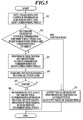
- the contour processing section 7 identifies a contour pixel of the object on the basis of the contour information OL inputted from the contour extraction section 4 and outputs image data la obtained by performing a dither process regarding contour enhancement on the contour pixel.
- the contour of the object the density of which is higher than that of the background is to be enhanced.
- the output determination section 8 determines the output value of each pixel on the basis of the image data SC inputted from the dither process section 6, the image data la inputted from the contour processing section 7, the image data IS inputted from the ⁇ process section 3, and the contour information OL inputted from the contour extraction section 4 and outputs output image data LA.
- a target pixel is first set for the image data IS inputted.
- the dither process section 6 then performs the dither process on the target pixel, calculates the output value SC of the target pixel, and outputs it to the output determination section 8.
- the image data IS pixel values
- the contour information OL for the target pixel and the eight surrounding pixels are inputted to the contour processing section 7 (step S1).
- the contour processing section 7 determines that the target pixel is a contour pixel of the object (Y in step S2), then a dither process is performed on the target pixel by using thresholds TH1 and TH2 corresponding to the eight surrounding pixels ("n" of 1 to 8 is used for identifying the eight surrounding pixels).
- the thresholds TH1 and TH2 corresponding to the eight surrounding pixels are found in the following way.
- the coordinates (i, j) of the target pixel in equations (1) and (2) are first replaced by the coordinates (ip, jp) of each of the eight surrounding pixels.
- the thresholds TH1 and TH2 are obtained by referring to the element value e in the look-up tables tb1 and tb2.
- dither output l ⁇ a n I ⁇ S ⁇ TH ⁇ 1 ⁇ 255 / TH ⁇ 2 ⁇ TH ⁇ 1 la[n] is dither output obtained by using thresholds for a surrounding pixel specified by n.
- dither outputs la[1] through la[8] for all the surrounding pixels are obtained and are outputted to the output determination section 8 (step S3).
- the output determination section 8 performs pattern matching on the target pixel and the eight surrounding pixels on the basis of their pixel values and the contour information OL inputted from the contour extraction section 4 by using templates shown in FIG. 6 (step S4) and determines whether the target pixel and the eight surrounding pixels match at least one template (step S5).
- a pixel indicated by A is a specific pixel to be detected
- a pixel indicated by B is a contour pixel of the object
- a pixel indicated by C is a pixel inside a contour pixel of the object
- a pixel indicated by D is a surrounding pixel for the target pixel and is outside the object.
- each template is placed so that the target pixel will be in the center of it.
- each template is rotated by 90 degrees. That is to say, if all of the ten templates shown in FIG. 6 are used, a matching process is performed on one target pixel forty times.
- condition (2) is required for performing a contour enhancement process only on an object the density of which is higher than that of a background. Whether condition (1) is met is determined on the basis of the contour information OL. Whether condition (2) is met is determined by comparing the pixel value of the target pixel with the pixel value of a surrounding pixel corresponding to a pixel indicated by D or A.
- the output determination section 8 performs a predetermined operation for a surrounding pixel [n] corresponding to a pixel in the template indicated by C, that is to say, for a surrounding pixel [n] detected as a specific pixel by using an output value la[n] calculated by the contour processing section 7 and determines an output value calculated by the operation as an output value LA of the target pixel (step S6).
- an output value la[n] that is the greatest of output values la[n] of specific pixels is calculated and is determined as the output value LA.
- Another operation may be performed. For example, the sum of output values la[n] of specific pixels may be determined as the output value LA. The weighted average of output values la[n] of specific pixels may be calculated. By using these operation methods, the output density of a contour portion can be controlled.
- an output value SC obtained by performing an ordinary dither process by using the thresholds for the target pixel is determined as an output value LA of the target pixel (step S7).
- the above process is performed on all pixels included in the image data IS inputted and an output value LA determined for each pixel is outputted as final output image data LA.
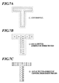
- an output value la[n] that is the greatest of output values la[n] obtained by performing a dither process by using thresholds for specific pixels (pixels which are in an area outside the object "T" enclosed by dotted lines shown in FIG. 7B) detected is outputted for each contour pixel (see FIG. 7A). Accordingly, an output result shown in FIG. 7C is obtained. As shown in FIG. 7C, dots are outputted in contour pixel portions of the object and contour enhancement succeeds. Moreover, by performing contour enhancement, the jaggy is eliminated and the thinning is lessened.
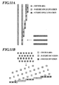
- FIG. 8A shows an output result obtained by performing a dither process on a large letter in a halftone.
- the distance between dots outputted as a result of the dither process is long in an area where density is uniformly low. Accordingly, a jaggy appears near the contour.
- an output value which is the greatest of output values obtained by performing a dither process by using thresholds for a dither process corresponding to pixels outside an object is considered as an output value of a target pixel, being a contour pixel.
- a dot output rate in contour pixel portions can be raised.
- dots are outputted in contour pixel portions by the contour enhancement process, so periodicity caused by a uniform dither process can be broken. This prevents periodic interference and avoids degradation in image quality caused by, for example, the appearance of moire. Intervals between dots are long especially in a low-density area.
- dots outputted as a result of the contour enhancement process are not touching dots which have been outputted as a result of an ordinary dither process, so degradation in image quality caused by a local increase in density at the printing stage can be prevented.
- periodicity caused by the dither process can be broken. Therefore, degradation in image quality caused by periodicity can be reduced.
- whether the target pixel is a contour pixel is determined on the basis of the pixel value of the target pixel and the pixel value of a surrounding pixel. Therefore, whether the target pixel is a contour pixel which forms part of the contour of the object can be determined with not only information regarding the target pixel but also information regarding the surrounding pixel taken into consideration.
- the contour enhancement process can be performed only if it is necessary to perform a dither process on the contour.
- thresholds for a dither process corresponding to a plurality of surrounding pixels outside the object are used for determining the output value of the target pixel.
- the output value can be determined according to circumstances and a more natural contour can be reproduced.
- the extent to which the contour is enhanced can be controlled by an operation.
- the contour of the object is enhanced.
- a process for decreasing the density of pixels in a contour portion can be performed after the above process to avoid unnecessary enhancement of the contour portion.
- thresholds for a cell element corresponding to a pixel outside the object are applied to the target pixel by shifting the screen cell with respect to the target pixel according to the template patterns.
- the present invention is not limited to such a case.
- the position of the target pixel may be shifted instead of shifting the screen cell.
- An example of a process in which the position of a target pixel is shifted is as follows.
Landscapes
- Engineering & Computer Science (AREA)
- Multimedia (AREA)
- Signal Processing (AREA)
- Facsimile Image Signal Circuits (AREA)
- Image Processing (AREA)
Applications Claiming Priority (1)
| Application Number | Priority Date | Filing Date | Title |
|---|---|---|---|
| JP2005177704A JP4501791B2 (ja) | 2005-06-17 | 2005-06-17 | 画像処理方法及び画像処理プログラム |
Publications (2)
| Publication Number | Publication Date |
|---|---|
| EP1734737A1 true EP1734737A1 (de) | 2006-12-20 |
| EP1734737B1 EP1734737B1 (de) | 2018-03-28 |
Family
ID=36072222
Family Applications (1)
| Application Number | Title | Priority Date | Filing Date |
|---|---|---|---|
| EP06250357.8A Ceased EP1734737B1 (de) | 2005-06-17 | 2006-01-24 | Bildverarbeitungsverfahren und Speichermedium für die Lagerung eines Bildverarbeitungsprogramms |
Country Status (3)
| Country | Link |
|---|---|
| US (1) | US20060285167A1 (de) |
| EP (1) | EP1734737B1 (de) |
| JP (1) | JP4501791B2 (de) |
Cited By (1)
| Publication number | Priority date | Publication date | Assignee | Title |
|---|---|---|---|---|
| EP2234386A2 (de) | 2009-03-23 | 2010-09-29 | Konica Minolta Business Technologies, Inc. | Bildverarbeitungsvorrichtung und Bildverarbeitungsverfahren |
Families Citing this family (7)
| Publication number | Priority date | Publication date | Assignee | Title |
|---|---|---|---|---|
| JP4173154B2 (ja) * | 2005-04-26 | 2008-10-29 | シャープ株式会社 | 画像処理方法、画像処理装置、画像形成装置、コンピュータプログラム及び記録媒体 |
| JP4779987B2 (ja) * | 2007-02-08 | 2011-09-28 | コニカミノルタビジネステクノロジーズ株式会社 | 画像処理装置及び画像処理方法 |
| JP5033579B2 (ja) * | 2007-10-31 | 2012-09-26 | 京セラドキュメントソリューションズ株式会社 | 画像出力装置、画像出力方法及び画像出力プログラム |
| JP4900175B2 (ja) * | 2007-10-04 | 2012-03-21 | セイコーエプソン株式会社 | 画像処理装置及び方法並びにプログラム |
| JP5055418B2 (ja) * | 2010-12-10 | 2012-10-24 | キヤノン株式会社 | 画像処理装置および画像処理方法 |
| JP6256125B2 (ja) * | 2014-03-13 | 2018-01-10 | 株式会社リコー | 画像形成装置 |
| JP7250574B2 (ja) * | 2019-03-11 | 2023-04-03 | キヤノン株式会社 | 画像形成装置、その制御方法、およびプログラム |
Citations (6)
| Publication number | Priority date | Publication date | Assignee | Title |
|---|---|---|---|---|
| US4084259A (en) * | 1973-11-30 | 1978-04-11 | The Mead Corporation | Apparatus for dot matrix recording |
| US4437122A (en) * | 1981-09-12 | 1984-03-13 | Xerox Corporation | Low resolution raster images |
| EP0356225A2 (de) * | 1988-08-24 | 1990-02-28 | Canon Kabushiki Kaisha | Bildverarbeitungsgerät |
| JPH09282471A (ja) | 1996-04-15 | 1997-10-31 | Canon Inc | 画像処理装置、画像形成装置およびその方法 |
| US6038348A (en) * | 1996-07-24 | 2000-03-14 | Oak Technology, Inc. | Pixel image enhancement system and method |
| JP2004040499A (ja) | 2002-07-03 | 2004-02-05 | Ricoh Co Ltd | 画像処理装置、画像処理システム、画像処理方法、およびコンピュータが実行するためのプログラム |
Family Cites Families (4)
| Publication number | Priority date | Publication date | Assignee | Title |
|---|---|---|---|---|
| JP2880541B2 (ja) * | 1989-11-15 | 1999-04-12 | 富士通株式会社 | ディザ画像の中間調推定方式 |
| JPH0465969A (ja) * | 1990-07-02 | 1992-03-02 | Oki Electric Ind Co Ltd | 画像処理装置 |
| JPH11261830A (ja) * | 1998-03-10 | 1999-09-24 | Konica Corp | 画像処理方法および画像処理装置 |
| TW384612B (en) * | 1998-08-19 | 2000-03-11 | Acer Peripherals Inc | Image processing system and method capable of converting gray-level images into binary images |
-
2005
- 2005-06-17 JP JP2005177704A patent/JP4501791B2/ja not_active Expired - Fee Related
- 2005-09-14 US US11/226,773 patent/US20060285167A1/en not_active Abandoned
-
2006
- 2006-01-24 EP EP06250357.8A patent/EP1734737B1/de not_active Ceased
Patent Citations (7)
| Publication number | Priority date | Publication date | Assignee | Title |
|---|---|---|---|---|
| US4084259A (en) * | 1973-11-30 | 1978-04-11 | The Mead Corporation | Apparatus for dot matrix recording |
| US4437122A (en) * | 1981-09-12 | 1984-03-13 | Xerox Corporation | Low resolution raster images |
| US4437122B1 (de) * | 1981-09-12 | 1993-03-30 | Xerox Corp | |
| EP0356225A2 (de) * | 1988-08-24 | 1990-02-28 | Canon Kabushiki Kaisha | Bildverarbeitungsgerät |
| JPH09282471A (ja) | 1996-04-15 | 1997-10-31 | Canon Inc | 画像処理装置、画像形成装置およびその方法 |
| US6038348A (en) * | 1996-07-24 | 2000-03-14 | Oak Technology, Inc. | Pixel image enhancement system and method |
| JP2004040499A (ja) | 2002-07-03 | 2004-02-05 | Ricoh Co Ltd | 画像処理装置、画像処理システム、画像処理方法、およびコンピュータが実行するためのプログラム |
Cited By (5)
| Publication number | Priority date | Publication date | Assignee | Title |
|---|---|---|---|---|
| EP2234386A2 (de) | 2009-03-23 | 2010-09-29 | Konica Minolta Business Technologies, Inc. | Bildverarbeitungsvorrichtung und Bildverarbeitungsverfahren |
| CN101848310A (zh) * | 2009-03-23 | 2010-09-29 | 柯尼卡美能达商用科技株式会社 | 图像处理设备和图像处理方法 |
| EP2234386A3 (de) * | 2009-03-23 | 2010-11-03 | Konica Minolta Business Technologies, Inc. | Bildverarbeitungsvorrichtung und Bildverarbeitungsverfahren |
| CN101848310B (zh) * | 2009-03-23 | 2013-07-17 | 柯尼卡美能达商用科技株式会社 | 图像处理设备和图像处理方法 |
| US9113104B2 (en) | 2009-03-23 | 2015-08-18 | Konica Minolta, Inc. | Image processing apparatus and image processing method to perform screen processing for image data |
Also Published As
| Publication number | Publication date |
|---|---|
| US20060285167A1 (en) | 2006-12-21 |
| JP2006352633A (ja) | 2006-12-28 |
| EP1734737B1 (de) | 2018-03-28 |
| JP4501791B2 (ja) | 2010-07-14 |
Similar Documents
| Publication | Publication Date | Title |
|---|---|---|
| CA2285843C (en) | Automated enhancement of print quality based on feature size, shape, orientation, and color | |
| EP1146472B1 (de) | Lose Mustervergleichung mit Grauwerten | |
| EP0855830B1 (de) | Unterscheidung zwischen Text/Linien und Halbtonrasterung zur Verbesserung der Bildelementauflösung | |
| US6377711B1 (en) | Methods and systems for detecting the edges of objects in raster images using diagonal edge detection | |
| JPH11341286A (ja) | エイリアスが除去された画素を含む画像の処理方法 | |
| JPH1070655A (ja) | 走査画像処理方法 | |
| US7218417B2 (en) | Resolution conversion using a morphological partial pixel mapping (MPPM) approach | |
| US7667711B2 (en) | Image processing system, a method thereof, and a recording medium thereof | |
| JPH11154226A (ja) | 解像度改善方法及び装置 | |
| EP1734737B1 (de) | Bildverarbeitungsverfahren und Speichermedium für die Lagerung eines Bildverarbeitungsprogramms | |
| JP4111190B2 (ja) | 画像処理装置 | |
| JP4386216B2 (ja) | カラープリントシステム及びその制御方法 | |
| AU2004225390B9 (en) | Methods and apparatus for dynamically soft proofing halftone images | |
| JP4605782B2 (ja) | デュアルハーフトーンを用いるレーザプリント装置 | |
| US6661921B2 (en) | Image process apparatus, image process method and storage medium | |
| JP2005184685A (ja) | 画像処理装置、プログラムおよび記録媒体 | |
| US20040150846A1 (en) | Color image halftoning apparatus and method, and mask generation apparatus and method used therein | |
| JP4507279B2 (ja) | 画像処理装置、画像処理方法及びそのプログラム | |
| US20050141037A1 (en) | Method and apparatus to enhance printing quality of laser printer | |
| EP2413584B1 (de) | Bildverarbeitungsvorrichtung, bildverarbeitungsverfahren und programm | |
| JP3669081B2 (ja) | 画像処理装置 | |
| EP2894841B1 (de) | Informationsverarbeitungsvorrichtung, Informationsverarbeitungsverfahren und Speichermedium | |
| JP4968192B2 (ja) | 画像処理装置、画像処理プログラム、および画像処理方法 | |
| JP2878695B2 (ja) | 画像処理装置および多値画像推定方法 | |
| JP2006067294A (ja) | 画像処理方法及び画像処理装置 |
Legal Events
| Date | Code | Title | Description |
|---|---|---|---|
| PUAI | Public reference made under article 153(3) epc to a published international application that has entered the european phase |
Free format text: ORIGINAL CODE: 0009012 |
|
| AK | Designated contracting states |
Kind code of ref document: A1 Designated state(s): AT BE BG CH CY CZ DE DK EE ES FI FR GB GR HU IE IS IT LI LT LU LV MC NL PL PT RO SE SI SK TR |
|
| AX | Request for extension of the european patent |
Extension state: AL BA HR MK YU |
|
| 17P | Request for examination filed |
Effective date: 20070521 |
|
| AKX | Designation fees paid |
Designated state(s): DE FR GB |
|
| 17Q | First examination report despatched |
Effective date: 20120529 |
|
| GRAP | Despatch of communication of intention to grant a patent |
Free format text: ORIGINAL CODE: EPIDOSNIGR1 |
|
| INTG | Intention to grant announced |
Effective date: 20171109 |
|
| GRAS | Grant fee paid |
Free format text: ORIGINAL CODE: EPIDOSNIGR3 |
|
| GRAA | (expected) grant |
Free format text: ORIGINAL CODE: 0009210 |
|
| AK | Designated contracting states |
Kind code of ref document: B1 Designated state(s): DE FR GB |
|
| REG | Reference to a national code |
Ref country code: GB Ref legal event code: FG4D |
|
| REG | Reference to a national code |
Ref country code: DE Ref legal event code: R096 Ref document number: 602006054998 Country of ref document: DE |
|
| REG | Reference to a national code |
Ref country code: DE Ref legal event code: R097 Ref document number: 602006054998 Country of ref document: DE |
|
| PLBE | No opposition filed within time limit |
Free format text: ORIGINAL CODE: 0009261 |
|
| STAA | Information on the status of an ep patent application or granted ep patent |
Free format text: STATUS: NO OPPOSITION FILED WITHIN TIME LIMIT |
|
| 26N | No opposition filed |
Effective date: 20190103 |
|
| P01 | Opt-out of the competence of the unified patent court (upc) registered |
Effective date: 20230510 |
|
| PGFP | Annual fee paid to national office [announced via postgrant information from national office to epo] |
Ref country code: GB Payment date: 20231130 Year of fee payment: 19 |
|
| PGFP | Annual fee paid to national office [announced via postgrant information from national office to epo] |
Ref country code: FR Payment date: 20231212 Year of fee payment: 19 |
|
| PGFP | Annual fee paid to national office [announced via postgrant information from national office to epo] |
Ref country code: DE Payment date: 20231205 Year of fee payment: 19 |
|
| REG | Reference to a national code |
Ref country code: DE Ref legal event code: R119 Ref document number: 602006054998 Country of ref document: DE |
|
| GBPC | Gb: european patent ceased through non-payment of renewal fee |
Effective date: 20250124 |
|
| PG25 | Lapsed in a contracting state [announced via postgrant information from national office to epo] |
Ref country code: DE Free format text: LAPSE BECAUSE OF NON-PAYMENT OF DUE FEES Effective date: 20250801 |
|
| PG25 | Lapsed in a contracting state [announced via postgrant information from national office to epo] |
Ref country code: GB Free format text: LAPSE BECAUSE OF NON-PAYMENT OF DUE FEES Effective date: 20250124 |
|
| PG25 | Lapsed in a contracting state [announced via postgrant information from national office to epo] |
Ref country code: FR Free format text: LAPSE BECAUSE OF NON-PAYMENT OF DUE FEES Effective date: 20250131 |