EP1735209B1 - Anpassbare nutzlastermöglichungsarchitektur - Google Patents
Anpassbare nutzlastermöglichungsarchitektur Download PDFInfo
- Publication number
- EP1735209B1 EP1735209B1 EP05733329A EP05733329A EP1735209B1 EP 1735209 B1 EP1735209 B1 EP 1735209B1 EP 05733329 A EP05733329 A EP 05733329A EP 05733329 A EP05733329 A EP 05733329A EP 1735209 B1 EP1735209 B1 EP 1735209B1
- Authority
- EP
- European Patent Office
- Prior art keywords
- payload
- assembly
- floor
- engagement
- support
- Prior art date
- Legal status (The legal status is an assumption and is not a legal conclusion. Google has not performed a legal analysis and makes no representation as to the accuracy of the status listed.)
- Revoked
Links
- 238000000034 method Methods 0.000 claims abstract description 16
- 230000003601 intercostal effect Effects 0.000 claims description 13
- 238000005192 partition Methods 0.000 claims description 7
- 230000008878 coupling Effects 0.000 claims description 6
- 238000010168 coupling process Methods 0.000 claims description 6
- 238000005859 coupling reaction Methods 0.000 claims description 6
- 230000000712 assembly Effects 0.000 description 12
- 238000000429 assembly Methods 0.000 description 12
- 230000000153 supplemental effect Effects 0.000 description 9
- 238000007789 sealing Methods 0.000 description 8
- 238000009434 installation Methods 0.000 description 5
- 239000000463 material Substances 0.000 description 5
- 238000004519 manufacturing process Methods 0.000 description 3
- 239000000565 sealant Substances 0.000 description 3
- 238000006243 chemical reaction Methods 0.000 description 1
- 239000002131 composite material Substances 0.000 description 1
- 238000010276 construction Methods 0.000 description 1
- 239000007799 cork Substances 0.000 description 1
- 230000009977 dual effect Effects 0.000 description 1
- 230000007246 mechanism Effects 0.000 description 1
- 239000002184 metal Substances 0.000 description 1
- 239000011120 plywood Substances 0.000 description 1
- 230000000284 resting effect Effects 0.000 description 1
- 125000006850 spacer group Chemical group 0.000 description 1
- 239000002699 waste material Substances 0.000 description 1
Images


Classifications
-
- B—PERFORMING OPERATIONS; TRANSPORTING
- B64—AIRCRAFT; AVIATION; COSMONAUTICS
- B64C—AEROPLANES; HELICOPTERS
- B64C1/00—Fuselages; Constructional features common to fuselages, wings, stabilising surfaces or the like
- B64C1/18—Floors
- B64C1/20—Floors specially adapted for freight
-
- B—PERFORMING OPERATIONS; TRANSPORTING
- B64—AIRCRAFT; AVIATION; COSMONAUTICS
- B64D—EQUIPMENT FOR FITTING IN OR TO AIRCRAFT; FLIGHT SUITS; PARACHUTES; ARRANGEMENT OR MOUNTING OF POWER PLANTS OR PROPULSION TRANSMISSIONS IN AIRCRAFT
- B64D9/00—Equipment for handling freight; Equipment for facilitating passenger embarkation or the like
- B64D9/003—Devices for retaining pallets or freight containers
-
- B—PERFORMING OPERATIONS; TRANSPORTING
- B64—AIRCRAFT; AVIATION; COSMONAUTICS
- B64C—AEROPLANES; HELICOPTERS
- B64C1/00—Fuselages; Constructional features common to fuselages, wings, stabilising surfaces or the like
- B64C2001/0018—Fuselages; Constructional features common to fuselages, wings, stabilising surfaces or the like comprising two decks adapted for carrying passengers only
- B64C2001/0027—Fuselages; Constructional features common to fuselages, wings, stabilising surfaces or the like comprising two decks adapted for carrying passengers only arranged one above the other
-
- B—PERFORMING OPERATIONS; TRANSPORTING
- B64—AIRCRAFT; AVIATION; COSMONAUTICS
- B64C—AEROPLANES; HELICOPTERS
- B64C1/00—Fuselages; Constructional features common to fuselages, wings, stabilising surfaces or the like
- B64C2001/0045—Fuselages characterised by special shapes
-
- Y—GENERAL TAGGING OF NEW TECHNOLOGICAL DEVELOPMENTS; GENERAL TAGGING OF CROSS-SECTIONAL TECHNOLOGIES SPANNING OVER SEVERAL SECTIONS OF THE IPC; TECHNICAL SUBJECTS COVERED BY FORMER USPC CROSS-REFERENCE ART COLLECTIONS [XRACs] AND DIGESTS
- Y02—TECHNOLOGIES OR APPLICATIONS FOR MITIGATION OR ADAPTATION AGAINST CLIMATE CHANGE
- Y02T—CLIMATE CHANGE MITIGATION TECHNOLOGIES RELATED TO TRANSPORTATION
- Y02T50/00—Aeronautics or air transport
- Y02T50/40—Weight reduction
Definitions
- This invention relates generally to apparatus and methods for situating and securing payloads to support structures, and more specifically, to adaptable payload enabling architecture.
- modem commercial aircraft is manufactured in accordance with the particular requirements of the aircraft owner.
- One such aspect is the arrangement of the various components within the cabin of the aircraft, including the galleys, lavatories, passenger seats, cargo containers, section partitions, and other aircraft components.
- additional structure within the cabin of the aircraft is typically added as needed to account for larger than average loading caused by heavy monuments (e.g. lavatories, galleys, etc.) set between the floor and ceiling.
- heavy monuments e.g. lavatories, galleys, etc.
- the floor, and potentially the walls and ceiling need to be designed (or redesigned) to account for all potential monument locations.
- FIGURE 1 is a side, partial cross-sectional view of a conventional floor assembly 50 and a payload assembly 52 in accordance with the prior art.
- FIGURE 2 is a top elevational view of the conventional floor assembly 50 and payload assembly 52 of FIGURE 1 .
- the conventional floor assembly 50 includes a plurality of seat tracks 54 that extend longitudinally along the cabin of the aircraft.
- the seat tracks 54 are adapted to be coupled to a plurality of seat assemblies or other aircraft components, which may be positioned at desired locations along the seat tracks 54.
- Supplemental support members 56 are interspersed among the seat tracks 54 and extend beneath one or more of the payload assemblies 52 ( FIGURE 2 ).
- a plurality of floor panels 58 are disposed between the seat tracks 54 and the supplemental support members 56.
- sealant 60 is installed in the gap between the floor panel 58 edges and seat track 54 & 56 edges and plugs 62 are installed in the unused, exposed portions of the seat tracks 54 and the supplemental support members 56 in some areas of the cabin.
- sealing tape (not shown), which is several inches wide, is installed over the sealed gap to minimize leakage between the floor panels 58 and the associated seat tracks 54 and supplemental support members 56.
- the desired locations of the payload assemblies 52 e.g. galleys, lavatories, etc
- the payload assemblies 52 e.g. galleys, lavatories, etc
- the desired locations of the payload assemblies 52 often do not align with the seat tracks 54, so that the supplemental support members 56 must be added to carry the loads.
- a payload assembly 52 such as a galley
- a galley area mat (not shown) must be removed.
- payloads where the galley is going to be placed must also be removed (setting off another chain reaction of tasks). Sealing tape and sealant around the initial position of the galley must be removed.
- floor panels around the initial position of the galley must be removed.
- the supplemental support members 56 are typically added over the entire portion of the aircraft cabin known as the flex-zone in which the payload assemblies 52 may be desirably located so that they will not need to be added later when a move is desired.
- this practice increases manufacturing costs, and also adds unnecessary weight to the aircraft which increases operational costs. Therefore, novel support structures and payload assemblies which at least partially mitigate these characteristics would be useful.
- US 6068 214 describes a system for securing a support to an aircraft floor that includes stringers in the form of U-rails.
- a pallet carrying aircraft passenger seats is secured to an adapter that fits slidably into the U-rails.
- the present invention is directed to apparatus and methods for situating and securing payloads to support structures.
- Embodiments of apparatus and methods in accordance with the present invention may advantageously reduce the labor and expense associated with manufacturing a support structure in a passenger cabin of an aircraft, and with moving a payload within a cabin, in comparison with prior art apparatus and methods.
- embodiments of apparatus and methods in accordance with the present invention may reduce the weight of the support structure, thereby reducing the operating costs of the aircraft.
- an assembly in one embodiment, includes a support structure, a floor assembly, and a payload assembly.
- the floor assembly includes a plurality of elongated engagement members coupled to the support structure, the engagement members being spaced apart and mostly parallel, each engagement member including an engagement surface.
- the payload assembly includes a payload component positioned proximate to the floor assembly, and at least one payload support coupled to the payload component and engaged with at least some of the engagement members, the payload support being adapted to transfer loads from the payload component to the floor assembly and being moveable with the payload component relative to the floor assembly.
- the payload support may be a structured floor panel designed to transfer loads from the payload to the floor structure.
- the payload support might be an intercostal attached to, or resting under a payload floor panel.
- the payload support might be the outside edge of a partition. All payload supports transfer loads from the payload component to the aircraft structure directly or indirectly thru floor structure.
- the present invention relates to apparatus and methods for situating and securing payloads to support structures, and more specifically, to adaptable payload enabling architecture.
- Many specific details of certain embodiments of the invention are set forth in the following description and in FIGURES 3-8 to provide a thorough understanding of such embodiments.
- One skilled in the art, however, will understand that the present invention may have additional embodiments, or that the present invention may be practiced without several of the details described in the following description.
- FIGURE 3 is a side, partial cross-sectional view of a support structure 100 and an adaptable payload assembly 120 in accordance with an embodiment of the present invention.
- FIGURE 4 is a top elevational view of the support structure 100 and the adaptable payload assembly 120 of FIGURE 3 .
- the support structure 100 includes a plurality of floor panels 106, and a plurality of elongated floor supports 102 disposed beneath the floor panels 106 and extending longitudinally along the cabin of the aircraft. Most importantly is what is missing.
- Special support members, such as supplemental support members 56 of FIGURE 1 for payloads are not needed because the payloads can attach to the basic and stable enabling architecture provided by the seat tracks used for the seats.
- Small and numerous floor panels are not needed because floor panels no longer "break” on special support members and no longer "break” on seat tracks not needed for payload attachment. Instead, larger floor panels can be used which extend over aforementioned special support members and seat tracks.
- Each of the floor supports 102 includes an engagement surface 104 ( FIGURE 3 ) that engages a lower surface of one or more of the floor panels 106.
- Each of the floor supports 102 is situated significantly below the top surface of the floor panels 106 (and does not protrude above the top surface), and the engagement surface 104 is engaged against the lower surface of the floor panels 106. More specifically, in the embodiment shown in FIGURE 3 , the engagement surfaces 104 are approximately "flush" (as defined below) with or recessed below the lower surfaces of the floor panels 106 (and with the payload panel 124).
- the payload panel 124 is a trim element around and optionally under payload components structured to carry traffic loads (people walking, etc.). If a payload panel is strong enough to beam payload loads to surrounding floor structure, then it is also considered to be the payload support serving a dual role.
- the engagement surface 104 may engage the lower surface of the floor panels 106 directly or indirectly, as a variety of materials or components may be disposed between the engagement surface 104 and the lower surface of the floor panels 106, including, for example, an insert spacer, a clip-nut, cork, tape, or other materials or components.
- flush and “flush with” as used in this patent application when referring to the relationship between members that support floor panels (e.g. the engagement surface 104) and one or more adjacent surfaces (e.g. the lower surfaces of the floor panels 106, or other adjacent support surfaces that engage with the lower surfaces of the floor panels 106, etc.) should be construed as including “approximately flush” or “nearly flush,” and should not be construed as being limited to a precisely co-planar condition.
- the terms “flush” and “flush with” should be understood to include a condition of not significantly protruding above such adjacent surfaces.
- the engagement surface when the engagement surface is said to be "flush” with another surface, the engagement surface and the other surface need not be precisely co-planar, but rather, may be non-planar to a limited degree as long as a floor panel may extend continuously thereover without creating a tripping hazard or other unacceptable conditions.
- the term “flush” may include an engagement surface that is up to about 0.2 inches higher than an adjacent surface. In other embodiments, the term “flush” may include an engagement surface that is up to about 0.17 inches higher than an adjacent surface as determined by an amount a floor panel is allowed to bend over uneven surfaces.
- the term “flush” may include an engagement surface that is up to about 0.04 inches lower than an opposing surface such as the top skin of a floor panel. In further embodiments, a greater amount of non-planarity may be acceptable within the meaning of the term "flush” as used herein.
- the payload assembly 120 includes a primary component 122 coupled to a payload panel 124.
- the primary component 122 may be, for example, a galley, a lavatory, a passenger seat, an attendant seat, a crew seat, a closet, a cargo container, a section partition, a fireplace, shelving, a bed or other article of furniture, or any other component that may be located within the aircraft (or other vehicle or structure).
- embodiments of the present invention may be used to secure dividing devices (or partitions) within the passenger cabin of an aircraft, as generally disclosed, for example, in U.S. Patent No. 5,393,013 issued to Schneider et al. , and to secure cargo containers as generally disclosed, for example, in U.S. Patent No. 5,090,639 issued to Miller et al.
- the payload assembly 120 further includes an intercostal 130 transversely disposed between a pair of adjacent floor supports 102.
- a plurality of payload attachment assemblies 140 couple the payload panel 124 to the floor supports 102.
- the floor supports 102 are basic and stable members of the support structure 100.
- the payload panel 124 may be composed of any material or buildup that meets the requirements of the application.
- the payload panel 124 may be a composite sandwich panel, a plywood panel, a metal sheet, or any other suitable material or structure.
- the payload panels 124 may include one or more additional members (e.g.. the intercostal 130) that may be added when more load carrying capability is required so that such loads may be transmitted (or beamed) to adjacent basic and stable structure (e.g. the floor supports 102).
- the support structure 100 having the floor supports 102 that are "flush" with the lower surfaces of the floor panels 106 and with the lower surfaces of the payload panel 124 provide a suitable enabling architecture that allows the payload assembly 120 to be economically relocated to other positions. More specifically, the payload assembly 120 can be picked up and moved within the passenger cabin of the aircraft by detaching the attachment assemblies 140 from the floor supports 102, moving the payload assembly 120 to a new location, reattaching the attachment assemblies 140 at the new location, and sealing the periphery of the payload panel 124. The intercostal 130 moves with the payload panel 124 to the new location.
- the payload assembly 124 and components thereof may have a variety of alternate embodiments, and should not be construed as being limited to the particular embodiments shown and described herein, including the embodiment shown in FIGURE 3 .
- Embodiments of apparatus and methods in accordance with the present invention may provide significant advantages over the prior art. For example, because the floor supports are flush with the lower surfaces of the floor panels and the payload panels, these panels are not required to "break" at the locations of the floor supports. This allows the payload assembly to be moved with greater ease and economy in comparison with the prior art. Also, because the payload intercostal 130 attaches to basic and stable floor supports 102 and is movable with the payload assembly 120, the amount of support structure that is carried on the aircraft (or other vehicle or structure) may be reduced in comparison with the prior art. More specifically, the need for supplemental support members 56 ( FIGURE 1 ) that exist in the flex-zone areas of the cabin can be eliminated. The labor and expense associated with installation of the supplemental support members 56 is therefore reduced. Also, the unnecessary weight carried aboard the aircraft (or other vehicle or structure) is reduced, and the plugs 62 that must be installed in the unused, exposed portions of the seat tracks 54 are reduced.
- the labor and expense associated with moving the payload assembly 120 to a new location within the aircraft is also reduced.
- the payload assembly 120 includes an intercostal 130 that moves with the payload assembly 120
- the labor and expense associated with providing new supports at the new location is reduced or eliminated.
- the floor panels 106 and the payload panel 124 extend over the engagement surfaces of the floor supports 102 rather than "break" at the seat tracks 54 as shown in FIGURE 1 , the number of joints between the floor panels 106, 124 and the supports 102 is reduced. Therefore, the sealing requirements are simplified. More specifically, sealing between unlike materials, like the panels 106, 124 and the supports 102 is eliminated along common edges. Tape is simply applied over the joint between the floor panels 106 and the payload panel 124.
- FIGURE 5 is an upper isometric view of an adaptable payload assembly 200 in accordance with an alternate embodiment of the invention.
- FIGURE 6 is a lower isometric view of the adaptable payload assembly 200 of FIGURE 5 .
- the payload assembly 200 includes a primary component 202 coupled to a payload panel 204 and payload support 206 which are, in turn, coupled to a plurality of engagement members 208.
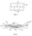
- FIGURE 7 is a top elevational view of one of the engagement members 208 of FIGURE 5 .
- the engagement member 208 has a plurality of coupling apertures 226 disposed therein.
- the engagement members 208 may have a variety of different coupling slots, apertures, or other suitable coupling mechanisms, such as the lug and opening coupling slot on existing aircraft (except a non-protruding version).
- a plurality of intercostals 206 are coupled to a bottom surface of the payload panel 204.
- the intercostals 206 extend transversely between and over adjacent pairs of engagement members 208 of a floor assembly 210.
- the engagement members 208 may be engaged, as with this example, with support beams 212 of a support frame (e.g. an aircraft airframe).
- the payload assembly 200 may provide the above-noted advantages of flexibility, adaptability, economy and weight savings in an alternate embodiment of the invention.
- FIGURE 8 is a side elevational view of an aircraft 800 in accordance with another alternate embodiment of the present invention.
- the various components and subsystems of the aircraft 800 may be of known construction and, for the sake of brevity, will not be described in detail herein.
- Embodiments of assemblies 802 for situating and securing payloads to support structures in accordance with the present invention may be employed in one or more desired locations throughout the aircraft 800.
- the aircraft 800 includes one or more propulsion units 804 coupled to an airframe 803 (not visible) disposed within a fuselage 805, wing assemblies 806 (or other lifting surfaces), a tail assembly 808, a landing assembly 810, a control system 812 (not visible), and a host of other systems and subsystems that enable proper operation of the aircraft 800.
- the assemblies for situating and securing payloads to support structures in accordance with the present invention are distributed throughout the various portions of the aircraft 800, including, for example, within the cockpit (802b); the first-class section (802c), and the coach or business class section (802a).
- the aircraft 800 shown in FIGURE 8 is generally representative of a commercial passenger aircraft, including, for example, the 737, 747, 757, 767, 777, and 7E7 models commercially-available from The Boeing Company of Chicago, Illinois, the inventive apparatus and methods disclosed herein may also be employed in virtually any other types of aircraft. More specifically, the teachings of the present invention may be applied to other types and models of passenger aircraft and military aircraft, and any other types of aircraft, including those described, for example, in The Illustrated Encyclopedia of Military Aircraft by Enzo Angelucci, published by Book Sales Publishers, September 2001 , and in Jane's All the World's Aircraft published by Jane's Information Group of Coulsdon, Surrey, United Kingdom , which texts are incorporated herein by reference. Furthermore, alternate embodiments of apparatus and methods in accordance with the present invention may be used in the other applications, including, for example, trucks, trailers, ships, buses, trains, recreational vehicles, subways, monorails, houses, apartments, office buildings, or any other desired application.
Landscapes
- Engineering & Computer Science (AREA)
- Aviation & Aerospace Engineering (AREA)
- Mechanical Engineering (AREA)
- Laminated Bodies (AREA)
- Building Environments (AREA)
- Connection Of Plates (AREA)
- Executing Machine-Instructions (AREA)
- Test And Diagnosis Of Digital Computers (AREA)
Claims (13)
- Anordnung mit:einer Trägerstruktur;einer Bodengruppe, die eine Mehrzahl von länglichen Eingriffselementen (102) beinhaltet, die mit der Trägerstruktur gekoppelt sind, wobei die Eingriffselemente (102) beabstandet und zumeist parallel sind und wobei jedes Eingriffselement (102) eine nach oben weisende Eingriffsfläche (104) beinhaltet; undeiner Nutzlastanordnung (120) einschließlicheiner Nutzlastkomponente (122), die nahe der Bodengruppe angeordnet ist;mindestens eines Nutzlastträgers (124), der mit der Nutzlastkomponente (122) gekoppelt ist und mit mindestens einigen der Eingriffsflächen der Eingriffselemente (102) in Eingriff steht, wobei der Nutzlastträger (124) ausgebildet ist, Lasten von der Nutzlastkomponente (122) zu der Bodengruppe zu übertragen, und mit der Nutzlastkomponente (122) in Bezug auf die Bodengruppe beweglich ist und dadurch gekennzeichnet ist, dass der Nutzlastträger (124) ein Zwischenelement (130) beinhaltet, das nach unten hervorsteht und sich zwischen einem Paar der nach oben weisenden Eingriffsflächen benachbarter Eingriffselemente (102) erstreckt.
- Anordnung nach Anspruch 1, wobei der Nutzlastträger (124) mindestens eines der folgenden Elemente beinhaltet: ein strukturiertes Nutzlastbodenpaneel (124), ein Zwischenteil (130) und ein Strukturbauteil und wobei sich der Nutzlastträger (124) von der Nutzlastkomponente (122) zu mindestens einem Befestigungspunkt zu und über einer zentralen lasttragenden Achse eines oder mehrerer Eingriffselemente (102) erstreckt.
- Anordnung nach Anspruch 1, wobei die Nutzlastanordnung (120) ferner mindestens ein Nutzlastpaneel (124) beinhaltet, wobei das Nutzlastpaneel (124) gekoppelt oder einstückig ist mit dem Nutzlastträger und/oder der Nutzlastkomponente (122).
- Anordnung nach Anspruch 1, wobei die Nutzlastanordnung (120) ferner mindestens einen Nutzlastträger beinhaltet, der mit mindestens einer der Eingriffsflächen (104) der Bodengruppe gekoppelt ist, wobei die Eingriffsfläche (104) mit einer Unterseite des Nutzlastpaneels (124) "bündig" und/oder darunter zurückgesetzt ist.
- Anordnung nach Anspruch 1, wobei die Bodengruppe ferner mindestens ein Bodenpaneel (106) beinhaltet, das mit mindestens einer der Eingriffsflächen (104) gekoppelt ist, wobei die Eingriffsfläche (104) mit einer Unterseite des Bodenpaneels (106) "bündig" und/oder darunter zurückgesetzt ist.
- Anordnung nach Anspruch 1, wobei die Bodengruppe ferner mindestens ein Bodenpaneel (106) beinhaltet, das mit mindestens einer der Eingriffsflächen (104) gekoppelt ist, und wobei die Nutzlastanordnung ferner mindestens ein Nutzlastpaneel (124) beinhaltet, das mit mindestens einer der Eingriffsflächen (104) gekoppelt ist, wobei das Nutzlastpaneel (124) annähernd in einer Ebene mit dem Bodenpaneel (106) liegt und wobei die Eingriffsfläche (104) mit jeweiligen Unterseiten des Bodenpaneels (106) und des Nutzlastpaneels (124) bündig und/oder darunter zurückgesetzt ist.
- Anordnung nach Anspruch 1, wobei die Nutzlastkomponente (122) mindestens eines der folgenden Elemente umfasst: eine Bordküche, eine Toilette, einen Passagiersitz, einen Flugbegleitersitz, einen Besatzungssitz, einen Schrank, einen Frachtcontainer, eine Bereichstrennwand, eine Feuerstelle, ein Regal und ein Möbelstück.
- Anordnung nach Anspruch 1, wobei die Trägerstruktur ein Flugwerk eines Flugzeugs (500) umfasst und wobei die Nutzlastkomponente (122) mindestens eines der folgenden Elemente umfasst: eine Bordküche, eine Toilette, einen Passagiersitz, einen Flugbegleitersitz, einen Besatzungssitz, einen Schrank, einen Frachtcontainer, eine Bereichstrennwand, eine Feuerstelle, ein Regal und ein Möbelstück.
- Verfahren zum Sichern einer Nutzlast an einer Trägerstruktur, welches umfasst:Bereitstellen einer Trägerstruktur;Koppeln einer Mehrzahl länglicher Eingriffselemente (102) einer Bodengruppe mit der Trägerstruktur, wobei die Eingriffselemente (102) beabstandet und annähernd parallel sind und wobei jedes Eingriffselement (102) eine nach oben weisende Eingriffsfläche (104) beinhaltet; undBereitstellen einer Nutzlastanordnung (120), die eine Nutzlastkomponente (122) und einen Nutzlastträger (124) beinhaltet, der mit der Bodengruppe gekoppelt ist, wobei der Nutzlastträger (124) mit mindestens einigen der Eingriffsflächen der Eingriffselemente (102) der Bodengruppe in Eingriff steht und mit der Nutzlastkomponente (122) in Bezug auf die Eingriffselemente (102) beweglich ist, wobei der Nutzlastträger (124) ein Zwischenelement (130) beinhaltet, das nach unten hervorsteht und sich zwischen einem Paar der nach oben weisenden Eingriffsflächen benachbarter Eingriffselemente (102) erstreckt; undmindestens teilweises Übermitteln von Lasten von der Nutzlastkomponente (122) durch den Nutzlastträger an mindestens einige der Eingriffselemente (102), einschließlich des Übermittelns von Lasten durch das Zwischenelement (130) an die nach oben weisenden Eingriffsflächen benachbarter Eingriffselemente (102).
- Verfahren nach Anspruch 9, wobei das Bereitstellen einer Nutzlastanordnung (120) das Bereitstellen einer Nutzlastanordnung beinhaltet, die einen länglichen Nutzlastträger aufweist, welcher mit einer Unterseite der Nutzlastkomponente (122) gekoppelt ist und zumindest teilweise über einer Oberseite der Eingriffselemente (102) in Eingriff steht.
- Verfahren nach Anspruch 9, wobei das Bereitstellen einer Nutzlastanordnung (120) das Bereitstellen einer Nutzlastanordnung beinhaltet, die einen querverlaufenden Nutzlastträger aufweist, der sich von der Nutzlastkomponente zu mindestens einem Befestigungsort an einem oder mehreren benachbarten Eingriffselementen erstreckt.
- Verfahren nach Anspruch 11, welches ferner das Positionieren von mindestens einem Bodenpaneel benachbart zu und annähernd in einer Ebene mit dem mindestens einen Nutzlastpaneel sowie das Koppeln des mindestens einen Bodenpaneels mit mindestens einem der Eingriffselemente (102) umfasst.
- Verfahren nach Anspruch 9, wobei das Bereitstellen einer Nutzlastanordnung einschließlich einer Nutzlastkomponente (122) das Bereitstellen einer Nutzlastanordnung beinhaltet, die mindestens eines der folgenden Elemente aufweist: eine Bordküche, eine Toilette, einen Passagiersitz, einen Flugbegleitersitz, einen Besatzungssitz, einen Schrank, einen Frachtcontainer, eine Bereichstrennwand, eine Feuerstelle, ein Regal und ein Möbelstück.
Applications Claiming Priority (2)
| Application Number | Priority Date | Filing Date | Title |
|---|---|---|---|
| US10/811,787 US7195201B2 (en) | 2004-03-29 | 2004-03-29 | Adaptable payload enabling architecture |
| PCT/US2005/010248 WO2005095205A1 (en) | 2004-03-29 | 2005-03-28 | Adaptable payload enabling architecture |
Publications (2)
| Publication Number | Publication Date |
|---|---|
| EP1735209A1 EP1735209A1 (de) | 2006-12-27 |
| EP1735209B1 true EP1735209B1 (de) | 2009-05-13 |
Family
ID=34964822
Family Applications (1)
| Application Number | Title | Priority Date | Filing Date |
|---|---|---|---|
| EP05733329A Revoked EP1735209B1 (de) | 2004-03-29 | 2005-03-28 | Anpassbare nutzlastermöglichungsarchitektur |
Country Status (6)
| Country | Link |
|---|---|
| US (1) | US7195201B2 (de) |
| EP (1) | EP1735209B1 (de) |
| JP (1) | JP4744508B2 (de) |
| AT (1) | ATE431286T1 (de) |
| DE (1) | DE602005014458D1 (de) |
| WO (1) | WO2005095205A1 (de) |
Families Citing this family (24)
| Publication number | Priority date | Publication date | Assignee | Title |
|---|---|---|---|---|
| US7527222B2 (en) * | 2004-04-06 | 2009-05-05 | The Boeing Company | Composite barrel sections for aircraft fuselages and other structures, and methods and systems for manufacturing such barrel sections |
| US7134629B2 (en) | 2004-04-06 | 2006-11-14 | The Boeing Company | Structural panels for use in aircraft fuselages and other structures |
| US7159822B2 (en) * | 2004-04-06 | 2007-01-09 | The Boeing Company | Structural panels for use in aircraft fuselages and other structures |
| FR2872780B1 (fr) * | 2004-07-08 | 2006-11-17 | Airbus France Sas | Plancher pour aeronef |
| US7281685B2 (en) * | 2004-08-20 | 2007-10-16 | Airbus Deutschland Gmbh | Flush-top seat mounting rail for passenger aircraft |
| US7325771B2 (en) | 2004-09-23 | 2008-02-05 | The Boeing Company | Splice joints for composite aircraft fuselages and other structures |
| US7503368B2 (en) | 2004-11-24 | 2009-03-17 | The Boeing Company | Composite sections for aircraft fuselages and other structures, and methods and systems for manufacturing such sections |
| US8360362B2 (en) * | 2006-02-21 | 2013-01-29 | The Boeing Company | Aircraft floor and method of assembly |
| US8177184B2 (en) | 2006-12-21 | 2012-05-15 | The Boeing Company | Seat track assembly |
| US8033502B2 (en) * | 2007-01-26 | 2011-10-11 | EMBRAER—Empresa Brasileira de Aeronautica S.A. | Modular aircraft interior configuration and methods |
| US8388795B2 (en) | 2007-05-17 | 2013-03-05 | The Boeing Company | Nanotube-enhanced interlayers for composite structures |
| US8042767B2 (en) | 2007-09-04 | 2011-10-25 | The Boeing Company | Composite fabric with rigid member structure |
| US9284036B2 (en) * | 2007-12-27 | 2016-03-15 | Airbus Operations Gmbh | Floor plate for covering a floor framework in an aircraft |
| FR2939404B1 (fr) | 2008-12-09 | 2010-11-26 | Airbus France | Plancher modulaire pour aeronef |
| US8434728B2 (en) * | 2009-03-31 | 2013-05-07 | Production Resource Group, Llc | I-beam track with a separate attachment portion |
| US9126673B1 (en) | 2012-02-11 | 2015-09-08 | Air Methods Corporation | Patient transport vehicle flooring panel with built-in anti-slip tread |
| IL222208A (en) * | 2012-09-27 | 2017-02-28 | Israel Aerospace Ind Ltd | Loading system, method and facility |
| GB2516433B (en) * | 2013-07-19 | 2016-02-17 | British Airways Plc | Aircraft passenger seat fixing system |
| US9896185B2 (en) * | 2014-06-23 | 2018-02-20 | Greenpoint Technologies, Inc. | Aircraft interior flooring systems |
| US9738402B2 (en) * | 2014-06-30 | 2017-08-22 | The Boeing Company | Flight test equipment installation system and method |
| US11286050B2 (en) | 2018-02-15 | 2022-03-29 | The Boeing Company | Apparatus for adapting aircraft floors and related methods |
| US11203409B2 (en) | 2018-02-19 | 2021-12-21 | Charles J. Fenske | Geometric morphing wing with adaptive corrugated structure |
| US11180238B2 (en) * | 2018-11-19 | 2021-11-23 | The Boeing Company | Shear ties for aircraft wing |
| DE112022001400T5 (de) | 2021-03-08 | 2023-12-28 | Ancra International Llc | Frachtsystem mit konfigurationen für loses frachtgut und frachttransport |
Family Cites Families (46)
| Publication number | Priority date | Publication date | Assignee | Title |
|---|---|---|---|---|
| US2062243A (en) * | 1931-12-24 | 1936-11-24 | New York Central Railroad Co | Auto boxcar |
| US2422693A (en) * | 1944-09-15 | 1947-06-24 | Reconstruction Finance Corp | Attaching device |
| US2579003A (en) * | 1947-07-19 | 1951-12-18 | Josephian William | Vehicle construction |
| GB706614A (en) * | 1948-04-14 | 1954-03-31 | Fairey Aviat Co Ltd | Improvements in or relating to convertible aircraft |
| US2876969A (en) * | 1953-10-28 | 1959-03-10 | Fairchild Engine & Airplane | Aircraft transportable pallet floor |
| US2885133A (en) * | 1958-02-21 | 1959-05-05 | Robert D Grant | Self-adjusting orchard ladder |
| US3142461A (en) * | 1960-05-26 | 1964-07-28 | A T S Company Ltd | Internal fittings of aircraft |
| US3294034A (en) * | 1964-06-18 | 1966-12-27 | American Mach & Foundry | Cargo container for airplanes |
| US3478995A (en) * | 1967-09-21 | 1969-11-18 | Hughes Aircraft Co | Tie-down apparatus |
| US3578274A (en) * | 1968-10-31 | 1971-05-11 | Mc Donnell Douglas Corp | Pallet assembly |
| US3877671A (en) * | 1972-03-06 | 1975-04-15 | Hughes Aircraft Co | Unitary tie-down panel apparatus |
| US3904064A (en) * | 1973-11-23 | 1975-09-09 | Satco Inc | Cargo container with removable doors |
| US3908796A (en) * | 1974-10-04 | 1975-09-30 | Mathew Hurwitz | Self-levelling accessory for ladders |
| US3937298A (en) * | 1975-04-16 | 1976-02-10 | Mathew Hurwitz | Levelling attachment for ladders |
| US4000870A (en) * | 1975-09-08 | 1977-01-04 | Western Gear Corporation | Modular system for quick conversion of aircraft passenger compartments to cargo baggage/compartments |
| US4077590A (en) * | 1976-03-11 | 1978-03-07 | The Boeing Company | Integrated treadway cargo handling system |
| US4062298A (en) * | 1976-11-10 | 1977-12-13 | Uop Inc. | Anti rattle track fitting |
| DE3141869C2 (de) * | 1981-10-22 | 1984-02-02 | Messerschmitt-Bölkow-Blohm GmbH, 8000 München | Fußbodenkonstruktion für den oberen Laderaum eines Luftfahrzeuges |
| US4483499A (en) * | 1983-06-09 | 1984-11-20 | David Fronk | System and method for loading cargo into light aircraft |
| GB2167354B (en) | 1984-11-23 | 1989-06-07 | Fruehauf Corp | Cargo tie-down device |
| US4875645A (en) * | 1987-07-02 | 1989-10-24 | The Boeing Company | Modular cargo conveyor and restraint system for aircraft |
| US4911381A (en) * | 1987-12-28 | 1990-03-27 | Simula, Inc. | Energy-absorbing leg assembly for aircraft passenger seats |
| US4929133A (en) * | 1989-04-14 | 1990-05-29 | Airborne Express, Inc. | Loading pallet for aircraft cargo containers |
| EP0419914A1 (de) * | 1989-09-28 | 1991-04-03 | KRAUSE-WERK GMBH & CO. KG | Fuss für Leiterntraversen |
| US5090639A (en) * | 1989-10-26 | 1992-02-25 | United Parcel Service General Services Co. | Cargo-carrying system for passenger aircraft |
| US5083727A (en) * | 1990-01-02 | 1992-01-28 | The Boeing Company | Aircraft cabin system for selectivley locating interior units |
| US5178346A (en) * | 1991-07-12 | 1993-01-12 | Burns Aerospace Corporation | Track fastener apparatus and assembly |
| DE4141606C2 (de) * | 1991-12-17 | 1994-05-11 | Deutsche Aerospace Airbus | Vorrichtung zur Unterteilung einer Flugzeugkabine |
| US5322244A (en) * | 1992-03-17 | 1994-06-21 | Deutsche Aerospace Airbus Gmbh | Supply system for passenger aircraft |
| US5383630A (en) * | 1994-03-17 | 1995-01-24 | Teleflex Incorporated | Main deck quick change cargo system |
| DE4416506C2 (de) * | 1994-05-10 | 1999-12-02 | Daimler Chrysler Aerospace | Passagierflugzeug |
| FR2745260B1 (fr) * | 1996-02-28 | 1998-04-03 | Airbus Ind | Systeme et procede de conversion rapide et reversible d'un avion entre une configuration passagers et une configuration fret |
| US5823724A (en) * | 1996-07-29 | 1998-10-20 | New Haven Moving Equipment Corp. Of California, Inc. | End caps for tie-down track and process for installing a tie-down track |
| DE59709904D1 (de) * | 1997-01-10 | 2003-05-28 | Airbus Gmbh | Vorrichtung zum Transport und Befestigen von Frachtcontainern oder Sitzpaletten in einem Flugzeug |
| US6257522B1 (en) * | 1997-03-31 | 2001-07-10 | The Boeing Company | Multi-beam method and apparatus for removing and replacing major structural components while converting an airplane to efficiently carry freight |
| DE19742772C2 (de) * | 1997-09-27 | 1999-09-09 | Talbot Gmbh & Co Kg | Zwischenboden für einen Doppelstockwagen |
| US5871318A (en) * | 1997-11-12 | 1999-02-16 | Be Aerospace, Inc. | Quick-release track fastener |
| US6260813B1 (en) * | 2000-01-10 | 2001-07-17 | November Whiskey, Inc. | Aircraft seat track anchor fitting |
| US6414021B1 (en) * | 2000-08-25 | 2002-07-02 | Sucampo Ag | Control of intraocular pressure during surgery |
| US6514021B2 (en) * | 2001-02-28 | 2003-02-04 | David A. Delay | T-flange engaging load bearing bed |
| US6601798B2 (en) * | 2001-06-26 | 2003-08-05 | The Boeing Company | Seat track mounted passenger interface |
| DE10145276B4 (de) * | 2001-09-14 | 2008-04-10 | Deutsches Zentrum für Luft- und Raumfahrt e.V. | Flugzeug, insbesondere Passagierflugzeug, mit einem Rumpf, der eine tragende Primärstruktur und einen Frachtraum umfasst |
| US6619588B2 (en) * | 2002-01-14 | 2003-09-16 | The Boeing Company | Installation of single passenger interface unit and method thereof |
| US6554225B1 (en) * | 2002-06-14 | 2003-04-29 | The Boeing Company | Commercial aircraft low cost, lightweight floor design |
| DE10248241A1 (de) * | 2002-10-16 | 2004-05-06 | Airbus Deutschland Gmbh | Anordnung zur Verlegung von Kabeln im Fußbodenbereich eines Verkehrsflugzeuges |
| US6739281B1 (en) * | 2003-03-31 | 2004-05-25 | J. Scott Grimes | Reconfigurable boat deck |
-
2004
- 2004-03-29 US US10/811,787 patent/US7195201B2/en not_active Expired - Lifetime
-
2005
- 2005-03-28 EP EP05733329A patent/EP1735209B1/de not_active Revoked
- 2005-03-28 JP JP2007506414A patent/JP4744508B2/ja not_active Expired - Lifetime
- 2005-03-28 DE DE602005014458T patent/DE602005014458D1/de not_active Expired - Lifetime
- 2005-03-28 WO PCT/US2005/010248 patent/WO2005095205A1/en not_active Ceased
- 2005-03-28 AT AT05733329T patent/ATE431286T1/de not_active IP Right Cessation
Also Published As
| Publication number | Publication date |
|---|---|
| US7195201B2 (en) | 2007-03-27 |
| ATE431286T1 (de) | 2009-05-15 |
| JP4744508B2 (ja) | 2011-08-10 |
| US20050211840A1 (en) | 2005-09-29 |
| JP2007530365A (ja) | 2007-11-01 |
| EP1735209A1 (de) | 2006-12-27 |
| WO2005095205A1 (en) | 2005-10-13 |
| DE602005014458D1 (de) | 2009-06-25 |
Similar Documents
| Publication | Publication Date | Title |
|---|---|---|
| US7195201B2 (en) | Adaptable payload enabling architecture | |
| US7798447B2 (en) | Non-protruding seat track apparatus and methods | |
| US7093797B2 (en) | Adaptable payload apparatus and methods | |
| US7607613B2 (en) | Payload support track interface and fitting | |
| EP2441668B1 (de) | Frachtfördersystem mit geringer Bauhöhe | |
| US7051978B2 (en) | Adaptable payload processes | |
| EP2000406B1 (de) | Scherbeschlag für Frachtrollenträger | |
| EP3078592A1 (de) | Überkopf-gepäckablagebaugruppe für ein fahrzeug | |
| US11465747B2 (en) | Overhead support platform system for a vehicle | |
| US20090166472A1 (en) | Floor plate for covering a floor framework in an aircraft | |
| EP3922554B1 (de) | Monument mit befestigungssystem mit eckwinkelbeschlag | |
| US20230060580A1 (en) | System and method for passenger plane to cargo plane conversion | |
| US9815544B2 (en) | Modular replaceable slip joint intercostal | |
| US20250304254A1 (en) | Emergency oxygen systems for internal cabins of aircraft | |
| US11926420B2 (en) | Aircraft cabin partition system | |
| EP4186780A1 (de) | Seitenwand-boden-kupplungsanordnung für fahrzeugkabine und montageverfahren | |
| EP4678532A1 (de) | System und verfahren zur befestigung einer sitzanordnung an sitzschienen in einer internen kabine eines fahrzeugs |
Legal Events
| Date | Code | Title | Description |
|---|---|---|---|
| PUAI | Public reference made under article 153(3) epc to a published international application that has entered the european phase |
Free format text: ORIGINAL CODE: 0009012 |
|
| 17P | Request for examination filed |
Effective date: 20061017 |
|
| AK | Designated contracting states |
Kind code of ref document: A1 Designated state(s): AT BE BG CH CY CZ DE DK EE ES FI FR GB GR HU IE IS IT LI LT LU MC NL PL PT RO SE SI SK TR |
|
| RIN1 | Information on inventor provided before grant (corrected) |
Inventor name: JONES, TODD, EVAN Inventor name: GRETHER, MARTIN, R. Inventor name: FRANTZ, W., FORREST Inventor name: REED, RAYMOND, R. Inventor name: FORTADO, PAUL, R. Inventor name: PISCHKE, GINA, C. Inventor name: MORGAN, KELLY, L. Inventor name: HACKETT, DOUGLAS, W. |
|
| DAX | Request for extension of the european patent (deleted) | ||
| 17Q | First examination report despatched |
Effective date: 20070622 |
|
| GRAP | Despatch of communication of intention to grant a patent |
Free format text: ORIGINAL CODE: EPIDOSNIGR1 |
|
| GRAS | Grant fee paid |
Free format text: ORIGINAL CODE: EPIDOSNIGR3 |
|
| GRAA | (expected) grant |
Free format text: ORIGINAL CODE: 0009210 |
|
| AK | Designated contracting states |
Kind code of ref document: B1 Designated state(s): AT BE BG CH CY CZ DE DK EE ES FI FR GB GR HU IE IS IT LI LT LU MC NL PL PT RO SE SI SK TR |
|
| REG | Reference to a national code |
Ref country code: GB Ref legal event code: FG4D |
|
| REG | Reference to a national code |
Ref country code: CH Ref legal event code: EP |
|
| REG | Reference to a national code |
Ref country code: IE Ref legal event code: FG4D |
|
| REF | Corresponds to: |
Ref document number: 602005014458 Country of ref document: DE Date of ref document: 20090625 Kind code of ref document: P |
|
| PG25 | Lapsed in a contracting state [announced via postgrant information from national office to epo] |
Ref country code: PT Free format text: LAPSE BECAUSE OF FAILURE TO SUBMIT A TRANSLATION OF THE DESCRIPTION OR TO PAY THE FEE WITHIN THE PRESCRIBED TIME-LIMIT Effective date: 20090913 Ref country code: FI Free format text: LAPSE BECAUSE OF FAILURE TO SUBMIT A TRANSLATION OF THE DESCRIPTION OR TO PAY THE FEE WITHIN THE PRESCRIBED TIME-LIMIT Effective date: 20090513 Ref country code: AT Free format text: LAPSE BECAUSE OF FAILURE TO SUBMIT A TRANSLATION OF THE DESCRIPTION OR TO PAY THE FEE WITHIN THE PRESCRIBED TIME-LIMIT Effective date: 20090513 Ref country code: ES Free format text: LAPSE BECAUSE OF FAILURE TO SUBMIT A TRANSLATION OF THE DESCRIPTION OR TO PAY THE FEE WITHIN THE PRESCRIBED TIME-LIMIT Effective date: 20090824 Ref country code: LT Free format text: LAPSE BECAUSE OF FAILURE TO SUBMIT A TRANSLATION OF THE DESCRIPTION OR TO PAY THE FEE WITHIN THE PRESCRIBED TIME-LIMIT Effective date: 20090513 |
|
| NLV1 | Nl: lapsed or annulled due to failure to fulfill the requirements of art. 29p and 29m of the patents act | ||
| PG25 | Lapsed in a contracting state [announced via postgrant information from national office to epo] |
Ref country code: SI Free format text: LAPSE BECAUSE OF FAILURE TO SUBMIT A TRANSLATION OF THE DESCRIPTION OR TO PAY THE FEE WITHIN THE PRESCRIBED TIME-LIMIT Effective date: 20090513 Ref country code: SE Free format text: LAPSE BECAUSE OF FAILURE TO SUBMIT A TRANSLATION OF THE DESCRIPTION OR TO PAY THE FEE WITHIN THE PRESCRIBED TIME-LIMIT Effective date: 20090813 Ref country code: NL Free format text: LAPSE BECAUSE OF FAILURE TO SUBMIT A TRANSLATION OF THE DESCRIPTION OR TO PAY THE FEE WITHIN THE PRESCRIBED TIME-LIMIT Effective date: 20090513 Ref country code: IS Free format text: LAPSE BECAUSE OF FAILURE TO SUBMIT A TRANSLATION OF THE DESCRIPTION OR TO PAY THE FEE WITHIN THE PRESCRIBED TIME-LIMIT Effective date: 20090913 Ref country code: PL Free format text: LAPSE BECAUSE OF FAILURE TO SUBMIT A TRANSLATION OF THE DESCRIPTION OR TO PAY THE FEE WITHIN THE PRESCRIBED TIME-LIMIT Effective date: 20090513 |
|
| PG25 | Lapsed in a contracting state [announced via postgrant information from national office to epo] |
Ref country code: DK Free format text: LAPSE BECAUSE OF FAILURE TO SUBMIT A TRANSLATION OF THE DESCRIPTION OR TO PAY THE FEE WITHIN THE PRESCRIBED TIME-LIMIT Effective date: 20090513 Ref country code: RO Free format text: LAPSE BECAUSE OF FAILURE TO SUBMIT A TRANSLATION OF THE DESCRIPTION OR TO PAY THE FEE WITHIN THE PRESCRIBED TIME-LIMIT Effective date: 20090513 Ref country code: EE Free format text: LAPSE BECAUSE OF FAILURE TO SUBMIT A TRANSLATION OF THE DESCRIPTION OR TO PAY THE FEE WITHIN THE PRESCRIBED TIME-LIMIT Effective date: 20090513 Ref country code: CZ Free format text: LAPSE BECAUSE OF FAILURE TO SUBMIT A TRANSLATION OF THE DESCRIPTION OR TO PAY THE FEE WITHIN THE PRESCRIBED TIME-LIMIT Effective date: 20090513 |
|
| PLBI | Opposition filed |
Free format text: ORIGINAL CODE: 0009260 |
|
| PG25 | Lapsed in a contracting state [announced via postgrant information from national office to epo] |
Ref country code: BE Free format text: LAPSE BECAUSE OF FAILURE TO SUBMIT A TRANSLATION OF THE DESCRIPTION OR TO PAY THE FEE WITHIN THE PRESCRIBED TIME-LIMIT Effective date: 20090513 Ref country code: SK Free format text: LAPSE BECAUSE OF FAILURE TO SUBMIT A TRANSLATION OF THE DESCRIPTION OR TO PAY THE FEE WITHIN THE PRESCRIBED TIME-LIMIT Effective date: 20090513 |
|
| PLAX | Notice of opposition and request to file observation + time limit sent |
Free format text: ORIGINAL CODE: EPIDOSNOBS2 |
|
| 26 | Opposition filed |
Opponent name: AIRBUS OPERATIONS GMBH/AIRBUS OPERATIONS SAS (FR)/ Effective date: 20100208 |
|
| PG25 | Lapsed in a contracting state [announced via postgrant information from national office to epo] |
Ref country code: BG Free format text: LAPSE BECAUSE OF FAILURE TO SUBMIT A TRANSLATION OF THE DESCRIPTION OR TO PAY THE FEE WITHIN THE PRESCRIBED TIME-LIMIT Effective date: 20090813 |
|
| PLBB | Reply of patent proprietor to notice(s) of opposition received |
Free format text: ORIGINAL CODE: EPIDOSNOBS3 |
|
| PG25 | Lapsed in a contracting state [announced via postgrant information from national office to epo] |
Ref country code: MC Free format text: LAPSE BECAUSE OF NON-PAYMENT OF DUE FEES Effective date: 20100331 Ref country code: GR Free format text: LAPSE BECAUSE OF FAILURE TO SUBMIT A TRANSLATION OF THE DESCRIPTION OR TO PAY THE FEE WITHIN THE PRESCRIBED TIME-LIMIT Effective date: 20090814 |
|
| REG | Reference to a national code |
Ref country code: CH Ref legal event code: PL |
|
| REG | Reference to a national code |
Ref country code: IE Ref legal event code: MM4A |
|
| PG25 | Lapsed in a contracting state [announced via postgrant information from national office to epo] |
Ref country code: IE Free format text: LAPSE BECAUSE OF NON-PAYMENT OF DUE FEES Effective date: 20100328 |
|
| PG25 | Lapsed in a contracting state [announced via postgrant information from national office to epo] |
Ref country code: LI Free format text: LAPSE BECAUSE OF NON-PAYMENT OF DUE FEES Effective date: 20100331 Ref country code: CH Free format text: LAPSE BECAUSE OF NON-PAYMENT OF DUE FEES Effective date: 20100331 |
|
| PG25 | Lapsed in a contracting state [announced via postgrant information from national office to epo] |
Ref country code: IT Free format text: LAPSE BECAUSE OF FAILURE TO SUBMIT A TRANSLATION OF THE DESCRIPTION OR TO PAY THE FEE WITHIN THE PRESCRIBED TIME-LIMIT Effective date: 20090513 |
|
| PLAB | Opposition data, opponent's data or that of the opponent's representative modified |
Free format text: ORIGINAL CODE: 0009299OPPO |
|
| R26 | Opposition filed (corrected) |
Opponent name: AIRBUS OPERATIONS GMBH/AIRBUS OPERATIONS SAS (FR)/ Effective date: 20100208 |
|
| PG25 | Lapsed in a contracting state [announced via postgrant information from national office to epo] |
Ref country code: CY Free format text: LAPSE BECAUSE OF FAILURE TO SUBMIT A TRANSLATION OF THE DESCRIPTION OR TO PAY THE FEE WITHIN THE PRESCRIBED TIME-LIMIT Effective date: 20090513 |
|
| PG25 | Lapsed in a contracting state [announced via postgrant information from national office to epo] |
Ref country code: LU Free format text: LAPSE BECAUSE OF NON-PAYMENT OF DUE FEES Effective date: 20100328 Ref country code: HU Free format text: LAPSE BECAUSE OF FAILURE TO SUBMIT A TRANSLATION OF THE DESCRIPTION OR TO PAY THE FEE WITHIN THE PRESCRIBED TIME-LIMIT Effective date: 20091114 |
|
| PG25 | Lapsed in a contracting state [announced via postgrant information from national office to epo] |
Ref country code: TR Free format text: LAPSE BECAUSE OF FAILURE TO SUBMIT A TRANSLATION OF THE DESCRIPTION OR TO PAY THE FEE WITHIN THE PRESCRIBED TIME-LIMIT Effective date: 20090513 |
|
| RDAF | Communication despatched that patent is revoked |
Free format text: ORIGINAL CODE: EPIDOSNREV1 |
|
| APBM | Appeal reference recorded |
Free format text: ORIGINAL CODE: EPIDOSNREFNO |
|
| APBP | Date of receipt of notice of appeal recorded |
Free format text: ORIGINAL CODE: EPIDOSNNOA2O |
|
| APAH | Appeal reference modified |
Free format text: ORIGINAL CODE: EPIDOSCREFNO |
|
| APBQ | Date of receipt of statement of grounds of appeal recorded |
Free format text: ORIGINAL CODE: EPIDOSNNOA3O |
|
| REG | Reference to a national code |
Ref country code: FR Ref legal event code: PLFP Year of fee payment: 12 |
|
| PGFP | Annual fee paid to national office [announced via postgrant information from national office to epo] |
Ref country code: FR Payment date: 20160328 Year of fee payment: 12 Ref country code: GB Payment date: 20160329 Year of fee payment: 12 |
|
| PGFP | Annual fee paid to national office [announced via postgrant information from national office to epo] |
Ref country code: DE Payment date: 20160331 Year of fee payment: 12 |
|
| REG | Reference to a national code |
Ref country code: DE Ref legal event code: R064 Ref document number: 602005014458 Country of ref document: DE Ref country code: DE Ref legal event code: R103 Ref document number: 602005014458 Country of ref document: DE |
|
| APBU | Appeal procedure closed |
Free format text: ORIGINAL CODE: EPIDOSNNOA9O |
|
| RDAG | Patent revoked |
Free format text: ORIGINAL CODE: 0009271 |
|
| STAA | Information on the status of an ep patent application or granted ep patent |
Free format text: STATUS: PATENT REVOKED |
|
| 27W | Patent revoked |
Effective date: 20170119 |
|
| GBPR | Gb: patent revoked under art. 102 of the ep convention designating the uk as contracting state |
Effective date: 20170119 |