EP1736242A2 - Réservoir contenant des échangeurs d'ions, notamment dans un vehicule - Google Patents
Réservoir contenant des échangeurs d'ions, notamment dans un vehicule Download PDFInfo
- Publication number
- EP1736242A2 EP1736242A2 EP06115268A EP06115268A EP1736242A2 EP 1736242 A2 EP1736242 A2 EP 1736242A2 EP 06115268 A EP06115268 A EP 06115268A EP 06115268 A EP06115268 A EP 06115268A EP 1736242 A2 EP1736242 A2 EP 1736242A2
- Authority
- EP
- European Patent Office
- Prior art keywords
- housing
- ion exchange
- liquid
- heating
- ion exchanger
- Prior art date
- Legal status (The legal status is an assumption and is not a legal conclusion. Google has not performed a legal analysis and makes no representation as to the accuracy of the status listed.)
- Withdrawn
Links
Images


Classifications
-
- F—MECHANICAL ENGINEERING; LIGHTING; HEATING; WEAPONS; BLASTING
- F01—MACHINES OR ENGINES IN GENERAL; ENGINE PLANTS IN GENERAL; STEAM ENGINES
- F01N—GAS-FLOW SILENCERS OR EXHAUST APPARATUS FOR MACHINES OR ENGINES IN GENERAL; GAS-FLOW SILENCERS OR EXHAUST APPARATUS FOR INTERNAL-COMBUSTION ENGINES
- F01N3/00—Exhaust or silencing apparatus having means for purifying, rendering innocuous, or otherwise treating exhaust
- F01N3/08—Exhaust or silencing apparatus having means for purifying, rendering innocuous, or otherwise treating exhaust for rendering innocuous
- F01N3/10—Exhaust or silencing apparatus having means for purifying, rendering innocuous, or otherwise treating exhaust for rendering innocuous by thermal or catalytic conversion of noxious components of exhaust
- F01N3/18—Exhaust or silencing apparatus having means for purifying, rendering innocuous, or otherwise treating exhaust for rendering innocuous by thermal or catalytic conversion of noxious components of exhaust characterised by methods of operation; Control
- F01N3/20—Exhaust or silencing apparatus having means for purifying, rendering innocuous, or otherwise treating exhaust for rendering innocuous by thermal or catalytic conversion of noxious components of exhaust characterised by methods of operation; Control specially adapted for catalytic conversion
- F01N3/206—Adding periodically or continuously substances to exhaust gases for promoting purification, e.g. catalytic material in liquid form, NOx reducing agents
- F01N3/2066—Selective catalytic reduction [SCR]
-
- B—PERFORMING OPERATIONS; TRANSPORTING
- B01—PHYSICAL OR CHEMICAL PROCESSES OR APPARATUS IN GENERAL
- B01D—SEPARATION
- B01D53/00—Separation of gases or vapours; Recovering vapours of volatile solvents from gases; Chemical or biological purification of waste gases, e.g. engine exhaust gases, smoke, fumes, flue gases, aerosols
- B01D53/34—Chemical or biological purification of waste gases
- B01D53/92—Chemical or biological purification of waste gases of engine exhaust gases
-
- B—PERFORMING OPERATIONS; TRANSPORTING
- B01—PHYSICAL OR CHEMICAL PROCESSES OR APPARATUS IN GENERAL
- B01J—CHEMICAL OR PHYSICAL PROCESSES, e.g. CATALYSIS OR COLLOID CHEMISTRY; THEIR RELEVANT APPARATUS
- B01J47/00—Ion-exchange processes in general; Apparatus therefor
- B01J47/012—Ion-exchange processes in general; Apparatus therefor using portable ion-exchange apparatus
-
- B—PERFORMING OPERATIONS; TRANSPORTING
- B01—PHYSICAL OR CHEMICAL PROCESSES OR APPARATUS IN GENERAL
- B01J—CHEMICAL OR PHYSICAL PROCESSES, e.g. CATALYSIS OR COLLOID CHEMISTRY; THEIR RELEVANT APPARATUS
- B01J47/00—Ion-exchange processes in general; Apparatus therefor
- B01J47/02—Column or bed processes
- B01J47/06—Column or bed processes during which the ion-exchange material is subjected to a physical treatment, e.g. heat, electric current, irradiation or vibration
-
- C—CHEMISTRY; METALLURGY
- C02—TREATMENT OF WATER, WASTE WATER, SEWAGE, OR SLUDGE
- C02F—TREATMENT OF WATER, WASTE WATER, SEWAGE, OR SLUDGE
- C02F1/00—Treatment of water, waste water, or sewage
- C02F1/42—Treatment of water, waste water, or sewage by ion-exchange
-
- C—CHEMISTRY; METALLURGY
- C02—TREATMENT OF WATER, WASTE WATER, SEWAGE, OR SLUDGE
- C02F—TREATMENT OF WATER, WASTE WATER, SEWAGE, OR SLUDGE
- C02F2103/00—Nature of the water, waste water, sewage or sludge to be treated
- C02F2103/02—Non-contaminated water, e.g. for industrial water supply
- C02F2103/023—Water in cooling circuits
-
- F—MECHANICAL ENGINEERING; LIGHTING; HEATING; WEAPONS; BLASTING
- F01—MACHINES OR ENGINES IN GENERAL; ENGINE PLANTS IN GENERAL; STEAM ENGINES
- F01N—GAS-FLOW SILENCERS OR EXHAUST APPARATUS FOR MACHINES OR ENGINES IN GENERAL; GAS-FLOW SILENCERS OR EXHAUST APPARATUS FOR INTERNAL-COMBUSTION ENGINES
- F01N2610/00—Adding substances to exhaust gases
- F01N2610/02—Adding substances to exhaust gases the substance being ammonia or urea
-
- F—MECHANICAL ENGINEERING; LIGHTING; HEATING; WEAPONS; BLASTING
- F01—MACHINES OR ENGINES IN GENERAL; ENGINE PLANTS IN GENERAL; STEAM ENGINES
- F01N—GAS-FLOW SILENCERS OR EXHAUST APPARATUS FOR MACHINES OR ENGINES IN GENERAL; GAS-FLOW SILENCERS OR EXHAUST APPARATUS FOR INTERNAL-COMBUSTION ENGINES
- F01N2610/00—Adding substances to exhaust gases
- F01N2610/10—Adding substances to exhaust gases the substance being heated, e.g. by heating tank or supply line of the added substance
-
- F—MECHANICAL ENGINEERING; LIGHTING; HEATING; WEAPONS; BLASTING
- F01—MACHINES OR ENGINES IN GENERAL; ENGINE PLANTS IN GENERAL; STEAM ENGINES
- F01P—COOLING OF MACHINES OR ENGINES IN GENERAL; COOLING OF INTERNAL-COMBUSTION ENGINES
- F01P2060/00—Cooling circuits using auxiliaries
-
- Y—GENERAL TAGGING OF NEW TECHNOLOGICAL DEVELOPMENTS; GENERAL TAGGING OF CROSS-SECTIONAL TECHNOLOGIES SPANNING OVER SEVERAL SECTIONS OF THE IPC; TECHNICAL SUBJECTS COVERED BY FORMER USPC CROSS-REFERENCE ART COLLECTIONS [XRACs] AND DIGESTS
- Y02—TECHNOLOGIES OR APPLICATIONS FOR MITIGATION OR ADAPTATION AGAINST CLIMATE CHANGE
- Y02A—TECHNOLOGIES FOR ADAPTATION TO CLIMATE CHANGE
- Y02A50/00—TECHNOLOGIES FOR ADAPTATION TO CLIMATE CHANGE in human health protection, e.g. against extreme weather
- Y02A50/20—Air quality improvement or preservation, e.g. vehicle emission control or emission reduction by using catalytic converters
-
- Y—GENERAL TAGGING OF NEW TECHNOLOGICAL DEVELOPMENTS; GENERAL TAGGING OF CROSS-SECTIONAL TECHNOLOGIES SPANNING OVER SEVERAL SECTIONS OF THE IPC; TECHNICAL SUBJECTS COVERED BY FORMER USPC CROSS-REFERENCE ART COLLECTIONS [XRACs] AND DIGESTS
- Y02—TECHNOLOGIES OR APPLICATIONS FOR MITIGATION OR ADAPTATION AGAINST CLIMATE CHANGE
- Y02T—CLIMATE CHANGE MITIGATION TECHNOLOGIES RELATED TO TRANSPORTATION
- Y02T10/00—Road transport of goods or passengers
- Y02T10/10—Internal combustion engine [ICE] based vehicles
- Y02T10/12—Improving ICE efficiencies
Definitions
- the invention relates to a lonenhieler disposer, in particular in a motor vehicle, according to the preamble of claim 1.
- Such lonenleyer electer be used for example in the exhaust system of motor vehicles with an internal combustion engine to extract the water content in an aqueous urea solution calcium ions, whereby calcification of injectors is prevented, through which the aqueous urea solution is injected into the exhaust stream for oxygen reduction of nitrogen oxides.
- the ion exchanger causes a decalcification of the water content in the urea solution, whereby the life of the components in contact with the urea solution is increased.
- the problem here is that due to the relatively high proportion of water in the urea solution - the water content is about 2/3 - the freezing point of the solution is higher than occurring during severe frost temperatures, so there is a risk that the aqueous urea solution freezes.
- the invention is based on the problem to provide a lonenhieler practicer especially in a motor vehicle, in which simple measures to prevent damage to components at low temperatures. This should be done in particular without additional energy.
- a heating medium circuit is provided on the housing, wherein the heating means is guided in the heating medium circuit separately from the liquid which is passed through the ion exchanger tank.
- the cooling liquid of the internal combustion engine of the motor vehicle In the case of an application in a motor vehicle can be used as the heating means, the cooling liquid of the internal combustion engine of the motor vehicle.
- the cooling liquid is used for cooling the internal combustion engine, wherein after passing through the cylinder housing of the internal combustion engine, the heated coolant is expediently conducted into the ion exchanger tank for heating the liquid to be conducted through the ion exchange medium.
- the cooling liquid When using the cooling liquid as a heating means for the ion exchanger tank no additional energy input, for example by using an external heat source, is required.
- At least two housings are expediently provided in the ion exchanger container, of which the outer housing encloses an inner housing which contains the ion exchange agent.
- the liquid is passed through the inner housing with the ion exchange means therein, the heating medium being guided between the inner housing and the outer housing.
- the heating means is in particular passed through a helical heating cable, which is guided on the outside of the inner housing, ie between the inner and outer housing.
- a further housing is provided, which is arranged as an intermediate housing between the inner housing and the outer housing.
- the liquid is introduced into the lonenhieler employer, in outer space, however, the heating medium is guided. Both liquids are parallel over a large area, which promotes heat transfer from the heating means towards the liquid to be passed through the ion exchange means.
- a deformable expansion element adjoining the flow path of the liquid to be arranged in the housing.
- This expansion element is particularly elastically deformable and allows in the case of freezing of the liquid compensation of the larger volume of water content in the liquid.
- the expansion element yields under the pressure of the freezing and expanding fluid, thereby increasing the available volume in the fluid flow path. Due to the deformation of the expansion element, the high forces occurring during the freezing process can not lead to destruction of the ion exchanger tank or of parts of the ion exchanger tank.
- the deformable expansion element is designed, in particular, as a ring element radially delimiting the flow path of the liquid. Upon freezing of the liquid, the ring element yields radially outwardly.
- the expansion element for example in the form of two cross-shaped walls, which are arranged axially in the flow path of the liquid, but at low temperatures, the wall thicknesses are pressed together by the freezing liquid.
- the lonenleyerstoff is advantageously limited axially in the housing of a sliding boundary plate. Also, this slidable boundary plate allows volume compensation during freezing of the liquid to be passed.
- FIG. 1 shows a section through a lonenhieler actually which comprises three superposed housing, wherein in the inner housing a lonenhielerffen is arranged, through which a liquid is passed, the calcium ions or other ions to be withdrawn, and wherein an outer heating medium circuit provided for heating the liquid is
- Fig. 5 is an exploded perspective view of the inner housing of a lonenhieler disposers arranged therein, cross-shaped expansion element.
- Fig. 1 lonenleyer investigatinger 1 is for use in a motor vehicle.
- an aqueous urea solution which is injected into the exhaust gas stream for the purpose of oxygen reduction of nitrogen oxides is first passed through the ion exchanger tank in order to descalcify the water fraction in the aqueous urea solution.
- the ion exchanger calcium ions contained in the water portion are exchanged for sodium ions. In this way, the water is descaled, whereby a calcification of the coming into contact with the aqueous urea solution components is prevented.
- the ion exchange container 1 comprises three nested housings 2, 3 and 4, the inner housing 2 accommodating the ion exchange means 5 to be passed through by the aqueous urea solution.
- the aqueous urea solution is fed to the ion exchanger tank 1 via an inlet line 6 and, after flowing through the ion exchange means 5 in the inner housing 2, is discharged again via a drain line 7.
- the inflow line 6 and the drain line 7 are located After being introduced via the inflow line 6, the urea solution is conducted into a cylindrical intermediate space which is formed between the inner housing 2 and the intermediate housing 3.
- the urea solution flows down into the bottom area of the ion exchanger tank, where the urea solution flows into the interior of the inner housing 2 via an opening 2a located in the bottom of the inner housing 2.
- the urea solution flows through the interior and the lonenhielerstoff there located 5 from bottom to top and is discharged via a central outflow 8 in the lid portion of the inner housing 2 in the drain line 7.
- a heating medium is passed through the ion exchanger tank 1.
- a heating line 9 for receiving the heating means is helically placed in the intermediate space between the outer housing 4 and the intermediate housing 3.
- the heating medium flows through the helical heating line 9, wherein the heat of the heating medium is transmitted radially in the direction of arrow 10 inwards and thereby heats the aqueous urea solution which flows separately from the heating line 9 in the intermediate space between the inner housing 2 and the intermediate housing 3 down.
- the heating line 9 extends helically over the axial length of the ion exchange tank and ensures over the axial length for a uniform heat transfer to the urea solution. As a result, the temperature of the urea solution is maintained at a level that prevents freezing of the water content in the urea solution even at low outside temperatures.
- the heating medium and the aqueous urea solution are separated from each other by the ion exchanger tank 1 out. Since the heating means is guided in the heating line 9 and also the intermediate housing 3 is located between the heating line 9 and the aqueous urea solution, there is a double security against undesired mixing of both liquids in the event of breakage of a component.
- the heating means in particular the cooling liquid is used, which serves for the cooling of the internal combustion engine of the motor vehicle.
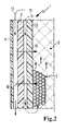
- a lonenhieler servinger 1 is shown in fragmentary form in a modified embodiment.
- the lonenleyer employer 1 comprises three housings 2, 3 and 4, between each of which a gap is formed.
- the aqueous urea solution can flow in the direction of arrow 11 through the inner space between the inner housing 2 and the intermediate housing 3 down.
- the heating means is passed in the direction of arrow 12 through the outer space between the outer housing 4 and the intermediate housing 3 down.
- the heating means is not performed in a heating line, but flows directly into the space between the housing 3 and 4 down.
- the heat transfer takes place in the direction of arrow 10 radially inwardly, whereby the urea solution is heated in the space between the housings 2 and 3 and in the interior of the inner housing 2.
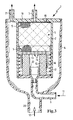
- FIG. 3 shows a further exemplary embodiment of an ion exchanger container 1.
- the container comprises in this embodiment, only two housings, namely an inner housing 2 and an outer housing 4.
- the inner housing 2 the lonenleyerstoff 5 is received, which is held axially downwardly by a slidably held in the inner housing 2 limiting disk 13, in the flow openings 14 for the Flow of the aqueous urea solution are introduced.
- the introduction of the aqueous urea solution takes place in the lower region of the ion exchanger tank via the inflow line 6 and the bottom of the inner housing 2.
- the aqueous urea solution flows through the flow openings 14 in the confining disc 13 and then comes into contact with the ion exchange means 5.
- the inner housing 2 forms a one-piece with a cover plate 19, in which the drain line 7 is introduced as a nozzle Plastic component; if necessary, a two-part design is also considered.
- the heating medium is also supplied to the lonenleyer knowledgeer 1 via the bottom.
- a nozzle 20 is formed in the bottom of the outer housing 4, via which the heating medium is conducted into the intermediate space between the inner housing 2 and the outer housing 4.
- a discharge nozzle 21 which is formed integrally with the cover plate 19 and thus also integrally with the inner housing 2, the heating means can be derived from the lonenleyer knowledgeer.
- an expansion element 15 which is designed as a ring element and directly adjacent to the opening in the bottom of the inner housing 2, via which the aqueous urea solution is supplied to the inner housing 2.
- the expansion element 15 is elastically deformable, it consists in particular of an elastomer such as EPDM. Radially outward, the expansion element 15 is supported by an annular wall 16, which is formed integrally with the limiting disc 13 and extends axially downwardly therefrom. Radially inwardly, the expansion element is fixed by a nozzle 22, which includes the inflow opening in the bottom and is formed integrally with the inner housing 2.
- a spiral-shaped spring element 17 is inserted, which supports the axially displaceable limiting disc 13 resiliently on the bottom of the inner housing 2.
- the deformable expansion element 15 can compensate for volume changes. If the aqueous urea solution freezes at low ambient temperatures, the wall of the expansion element 15 is compressed, whereby the due the freezing process occurring volume increase is compensated. Damage to the solid components in the ion exchanger tank 1 is prevented in this way.
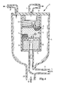
- Fig. 4 corresponds substantially to that of FIG. 3, but with differences in the interior of the inner housing 2.
- the lonenleyerstoff 5 is bounded axially by a respective limiting disc 13 and 23, the limiting disc 23 is axially displaceable in the interior of the inner housing 2 ,
- the limiting plate 13 is bounded by an axial stop in the inner housing 2 down. This stop is formed by webs 30, 31.
- the diameter of the inner housing 2 could serve as a stop when the diameter is reduced accordingly.
- an expansion element 15 is introduced into the interior of the inner housing 2, which is annular and, as in the aforementioned embodiment consists of an elastically deformable material, in particular of an elastomer such as EPDM.
- the lower boundary plate 13 is located, in which the flow openings 14 are introduced for the aqueous urea solution.
- the space for receiving the lonenleyerstoffs 5 is bounded above by the second limiting plate 23, in which also flow openings 24 are introduced for the exit of the aqueous urea solution.
- the upper limiting disk 23 is pressed down by a helical spring element 17.
- FIG. 5 only the inner housing 2 of a lonenleyer mattersers 1 is shown without heating circuit.
- an overhead fleece disc 18 is used, to which an expansion element 15 with two cross-shaped walls 28 and 29 follows.
- the walls 28 and 29 of the expansion element 15 are made of an elastically deformable material.
- the ion exchange agent is added.
- the walls 28 and 29, which are made of elastic material are compressed to provide compensation for the increased volume occupied by the frozen urea solution.
- a further fleece disc 25 is used, so that a total of two fleece discs 18 and 25 delimit the expansion element 15 axially on both end faces.
- the conclusion forms a sieve plate 26.
- an elastomeric disk 27 is placed on the inner housing 2, which is arranged in the assembled state of the lonenhieler mattersers 1 between the inner housing and the outer housing.
Landscapes
- Chemical & Material Sciences (AREA)
- Engineering & Computer Science (AREA)
- Chemical Kinetics & Catalysis (AREA)
- Organic Chemistry (AREA)
- Health & Medical Sciences (AREA)
- Environmental & Geological Engineering (AREA)
- Combustion & Propulsion (AREA)
- Hydrology & Water Resources (AREA)
- General Engineering & Computer Science (AREA)
- Life Sciences & Earth Sciences (AREA)
- Mechanical Engineering (AREA)
- Toxicology (AREA)
- Water Supply & Treatment (AREA)
- Biomedical Technology (AREA)
- Analytical Chemistry (AREA)
- General Chemical & Material Sciences (AREA)
- Oil, Petroleum & Natural Gas (AREA)
- Exhaust Gas After Treatment (AREA)
- Heat-Exchange Devices With Radiators And Conduit Assemblies (AREA)
- Treatment Of Water By Ion Exchange (AREA)
Applications Claiming Priority (1)
| Application Number | Priority Date | Filing Date | Title |
|---|---|---|---|
| DE202005009399U DE202005009399U1 (de) | 2005-06-14 | 2005-06-14 | Ionentauscherbehälter, insbesondere in einem Kraftfahrzeug |
Publications (2)
| Publication Number | Publication Date |
|---|---|
| EP1736242A2 true EP1736242A2 (fr) | 2006-12-27 |
| EP1736242A3 EP1736242A3 (fr) | 2007-02-07 |
Family
ID=37076156
Family Applications (1)
| Application Number | Title | Priority Date | Filing Date |
|---|---|---|---|
| EP06115268A Withdrawn EP1736242A3 (fr) | 2005-06-14 | 2006-06-12 | Réservoir contenant des échangeurs d'ions, notamment dans un vehicule |
Country Status (3)
| Country | Link |
|---|---|
| US (1) | US7601260B2 (fr) |
| EP (1) | EP1736242A3 (fr) |
| DE (1) | DE202005009399U1 (fr) |
Cited By (3)
| Publication number | Priority date | Publication date | Assignee | Title |
|---|---|---|---|---|
| DE102011009923A1 (de) | 2011-01-31 | 2012-08-02 | Mann + Hummel Gmbh | Ionentauscher zur Aufbereitung eines flüssigen Fluids |
| WO2012104282A1 (fr) * | 2011-01-31 | 2012-08-09 | Mann+Hummel Gmbh | Réservoir de compensation pour un fluide liquide et échangeur d'ions d'un réservoir de compensation |
| DE102015219710B4 (de) * | 2014-12-12 | 2025-07-03 | Hyundai Motor Company | Ionenfilter-Lebensdauer-Wahrnehmungseinrichtung für ein Brennstoffzellenfahrzeug |
Families Citing this family (3)
| Publication number | Priority date | Publication date | Assignee | Title |
|---|---|---|---|---|
| CN103657376A (zh) * | 2012-09-07 | 2014-03-26 | 实现科技股份有限公司 | 用于车辆、船舶或火力发电厂减排系统的尿素水纯化制备方法 |
| CN105107554A (zh) * | 2015-10-08 | 2015-12-02 | 武汉科技大学 | 一种用于含钒溶液离子交换的离子交换柱 |
| JP6945920B2 (ja) * | 2015-10-30 | 2021-10-06 | 一般財団法人電力中央研究所 | コンクリートキャスクの冷却空気量調節装置及びコンクリートキャスク |
Family Cites Families (12)
| Publication number | Priority date | Publication date | Assignee | Title |
|---|---|---|---|---|
| US1900821A (en) * | 1930-04-10 | 1933-03-07 | Joseph E Kline | Oil filter and cooler |
| DE3036936A1 (de) * | 1980-09-30 | 1982-05-27 | Linde Ag, 6200 Wiesbaden | Verfahren und vorrichtung zum regulieren des ammoniakgehaltes im waschmittel einer gaswaesche |
| US4383920A (en) * | 1981-05-29 | 1983-05-17 | Ecolochem, Inc. | Mobile fluid purification system |
| DE3222764A1 (de) * | 1982-06-18 | 1983-12-22 | GNS Gesellschaft für Nuklear-Service mbH, 4300 Essen | Abschirmbehaelter fuer die aufnahme von radioaktiven abfaellen |
| DE3403429A1 (de) * | 1984-02-01 | 1985-08-08 | Karl 7298 Loßburg Hehl | Kuehlereinheit fuer kunststoff-spritzgiessmaschine |
| US5692461A (en) * | 1990-02-27 | 1997-12-02 | Bg Products, Inc. | Apparatus and method for removing cations and anions from an engine coolant liquid |
| DE19935920C2 (de) * | 1999-07-30 | 2003-04-17 | Siemens Ag | Vorrichtung und Verfahren zum Beheizen eines Reduktionsmittelvorratsbehälters einer Abgasnachbehandlungsanlage für eine Brennkraftmaschine |
| DE10222102A1 (de) * | 2002-05-17 | 2003-11-27 | Basf Ag | Verfahren und Vorrichtung zum Kühlen eines Verbrennungsmotors |
| US6810661B2 (en) * | 2002-08-09 | 2004-11-02 | Ford Global Technologies, Llc | Method and system for freeze protecting liquid NOx reductants for vehicle application |
| JP2004230215A (ja) * | 2003-01-28 | 2004-08-19 | Nissan Motor Co Ltd | イオン交換樹脂フィルタ |
| DE202005000896U1 (de) * | 2004-11-30 | 2006-04-06 | Hengst Gmbh & Co.Kg | Ionentauscher |
| DE102005006243B4 (de) * | 2005-02-11 | 2007-05-31 | Daimlerchrysler Ag | Kraftfahrzeug mit Verbrennungsmotor und Abgasreinigungssystem |
-
2005
- 2005-06-14 DE DE202005009399U patent/DE202005009399U1/de not_active Expired - Lifetime
-
2006
- 2006-06-12 EP EP06115268A patent/EP1736242A3/fr not_active Withdrawn
- 2006-06-14 US US11/452,353 patent/US7601260B2/en active Active
Cited By (4)
| Publication number | Priority date | Publication date | Assignee | Title |
|---|---|---|---|---|
| DE102011009923A1 (de) | 2011-01-31 | 2012-08-02 | Mann + Hummel Gmbh | Ionentauscher zur Aufbereitung eines flüssigen Fluids |
| WO2012104282A1 (fr) * | 2011-01-31 | 2012-08-09 | Mann+Hummel Gmbh | Réservoir de compensation pour un fluide liquide et échangeur d'ions d'un réservoir de compensation |
| CN103329327A (zh) * | 2011-01-31 | 2013-09-25 | 曼·胡默尔有限公司 | 用于净化液体流体的离子交换器 |
| DE102015219710B4 (de) * | 2014-12-12 | 2025-07-03 | Hyundai Motor Company | Ionenfilter-Lebensdauer-Wahrnehmungseinrichtung für ein Brennstoffzellenfahrzeug |
Also Published As
| Publication number | Publication date |
|---|---|
| EP1736242A3 (fr) | 2007-02-07 |
| DE202005009399U1 (de) | 2006-10-19 |
| US7601260B2 (en) | 2009-10-13 |
| US20060278571A1 (en) | 2006-12-14 |
Similar Documents
| Publication | Publication Date | Title |
|---|---|---|
| DE19849492B4 (de) | Steuervorrichtung für einen Kühlkreislauf einer Brennkraftmaschine | |
| EP3136035B1 (fr) | Échangeur thermique à plaques comprenant une dérivation et procédé de fabrication d'un échangeur thermique à plaques comprenant d'une dérivation | |
| EP3255361B1 (fr) | Collecteur de réfrigérant et échangeur de chaleur comprenant un tel collecteur de réfrigérant | |
| EP2054132B1 (fr) | Ensemble filtre à huile | |
| DE102016209592B4 (de) | Ventil für ein Fahrzeug | |
| DE202022003081U1 (de) | Druckbehälter | |
| DE19961579A1 (de) | Flüssigkeitsfilter mit einem Kühler | |
| DE102011120798A1 (de) | Thermostatventil in Drehschieberbauform | |
| EP1736242A2 (fr) | Réservoir contenant des échangeurs d'ions, notamment dans un vehicule | |
| WO2016087064A1 (fr) | Pompe à carburant à comportement au refoulement amélioré | |
| WO2001081803A1 (fr) | Valve anti-retour | |
| EP1573237B1 (fr) | Bossage d'axe d'un piston pour un moteur a combustion interne | |
| EP2626526B1 (fr) | Dispositif de soupape | |
| EP3510835B1 (fr) | Élément chauffant annulaire | |
| EP1936141A2 (fr) | Soupape de réglage d'un milieu s'écoulant | |
| DE10003135A1 (de) | Ventil, insbesondere thermostatisches Ventil | |
| EP3818304B1 (fr) | Dispositif de protection antigel pour dispositif d'alimentation en eau dans un véhicule de loisir | |
| DE102022118621A1 (de) | Kälteanlage für überkritisches Kältemittel mit zusätzlichem Kältemittelspeicher für ein Kraftfahrzeug, Kraftfahrzeug mit einer solchen Kälteanlage | |
| EP3924614B1 (fr) | Dispositif de soupape | |
| DE202021106738U1 (de) | Druckbehälter | |
| DE102005004982A1 (de) | Gasfeder | |
| WO2007025517A1 (fr) | Dispositif et procede pour convertir de l'energie thermique en energie electrique | |
| DE102014224414A1 (de) | Einrichtung zur Integration eines Bypassventils in einen Kühlkreislauf | |
| DE102015212362B3 (de) | Kompressor mit Ventil sowie Verfahren zum Betrieb desselben | |
| EP4080047B1 (fr) | Dispositif de pompe |
Legal Events
| Date | Code | Title | Description |
|---|---|---|---|
| PUAI | Public reference made under article 153(3) epc to a published international application that has entered the european phase |
Free format text: ORIGINAL CODE: 0009012 |
|
| AK | Designated contracting states |
Kind code of ref document: A2 Designated state(s): AT BE BG CH CY CZ DE DK EE ES FI FR GB GR HU IE IS IT LI LT LU LV MC NL PL PT RO SE SI SK TR |
|
| AX | Request for extension of the european patent |
Extension state: AL BA HR MK YU |
|
| PUAL | Search report despatched |
Free format text: ORIGINAL CODE: 0009013 |
|
| RIC1 | Information provided on ipc code assigned before grant |
Ipc: F01N 3/20 20060101ALI20061222BHEP Ipc: B01J 47/06 20060101AFI20061018BHEP |
|
| AK | Designated contracting states |
Kind code of ref document: A3 Designated state(s): AT BE BG CH CY CZ DE DK EE ES FI FR GB GR HU IE IS IT LI LT LU LV MC NL PL PT RO SE SI SK TR |
|
| AX | Request for extension of the european patent |
Extension state: AL BA HR MK YU |
|
| 17P | Request for examination filed |
Effective date: 20070319 |
|
| 17Q | First examination report despatched |
Effective date: 20070625 |
|
| AKX | Designation fees paid |
Designated state(s): AT BE BG CH CY CZ DE DK EE ES FI FR GB GR HU IE IS IT LI LT LU LV MC NL PL PT RO SE SI SK TR |
|
| GRAP | Despatch of communication of intention to grant a patent |
Free format text: ORIGINAL CODE: EPIDOSNIGR1 |
|
| INTG | Intention to grant announced |
Effective date: 20151030 |
|
| STAA | Information on the status of an ep patent application or granted ep patent |
Free format text: STATUS: THE APPLICATION IS DEEMED TO BE WITHDRAWN |
|
| 18D | Application deemed to be withdrawn |
Effective date: 20160310 |