EP1736377A2 - Fahrzeuginnenplatte - Google Patents
Fahrzeuginnenplatte Download PDFInfo
- Publication number
- EP1736377A2 EP1736377A2 EP06012632A EP06012632A EP1736377A2 EP 1736377 A2 EP1736377 A2 EP 1736377A2 EP 06012632 A EP06012632 A EP 06012632A EP 06012632 A EP06012632 A EP 06012632A EP 1736377 A2 EP1736377 A2 EP 1736377A2
- Authority
- EP
- European Patent Office
- Prior art keywords
- vehicle interior
- interior panel
- tearing
- skin member
- layer
- Prior art date
- Legal status (The legal status is an assumption and is not a legal conclusion. Google has not performed a legal analysis and makes no representation as to the accuracy of the status listed.)
- Granted
Links
- 229920005749 polyurethane resin Polymers 0.000 claims description 3
- 239000000463 material Substances 0.000 description 18
- 229920005989 resin Polymers 0.000 description 9
- 239000011347 resin Substances 0.000 description 9
- 229920005862 polyol Polymers 0.000 description 8
- 150000003077 polyols Chemical class 0.000 description 8
- 238000000465 moulding Methods 0.000 description 7
- 238000010107 reaction injection moulding Methods 0.000 description 6
- 238000001746 injection moulding Methods 0.000 description 5
- 229920005830 Polyurethane Foam Polymers 0.000 description 4
- 239000011496 polyurethane foam Substances 0.000 description 4
- 230000000994 depressogenic effect Effects 0.000 description 3
- 238000005187 foaming Methods 0.000 description 3
- 229920002635 polyurethane Polymers 0.000 description 3
- 239000004814 polyurethane Substances 0.000 description 3
- 230000003014 reinforcing effect Effects 0.000 description 3
- 239000004743 Polypropylene Substances 0.000 description 2
- 229920000147 Styrene maleic anhydride Polymers 0.000 description 2
- 230000006835 compression Effects 0.000 description 2
- 238000007906 compression Methods 0.000 description 2
- 238000010030 laminating Methods 0.000 description 2
- -1 polypropylene Polymers 0.000 description 2
- 229920001155 polypropylene Polymers 0.000 description 2
- 238000000926 separation method Methods 0.000 description 2
- 239000000454 talc Substances 0.000 description 2
- 229910052623 talc Inorganic materials 0.000 description 2
- PYSRRFNXTXNWCD-UHFFFAOYSA-N 3-(2-phenylethenyl)furan-2,5-dione Chemical compound O=C1OC(=O)C(C=CC=2C=CC=CC=2)=C1 PYSRRFNXTXNWCD-UHFFFAOYSA-N 0.000 description 1
- JOYRKODLDBILNP-UHFFFAOYSA-N Ethyl urethane Chemical compound CCOC(N)=O JOYRKODLDBILNP-UHFFFAOYSA-N 0.000 description 1
- PEEHTFAAVSWFBL-UHFFFAOYSA-N Maleimide Chemical compound O=C1NC(=O)C=C1 PEEHTFAAVSWFBL-UHFFFAOYSA-N 0.000 description 1
- 239000004721 Polyphenylene oxide Substances 0.000 description 1
- 229920000122 acrylonitrile butadiene styrene Polymers 0.000 description 1
- 239000000956 alloy Substances 0.000 description 1
- 229910045601 alloy Inorganic materials 0.000 description 1
- 230000000052 comparative effect Effects 0.000 description 1
- 230000000593 degrading effect Effects 0.000 description 1
- 238000011161 development Methods 0.000 description 1
- 238000002474 experimental method Methods 0.000 description 1
- 239000000945 filler Substances 0.000 description 1
- 239000006260 foam Substances 0.000 description 1
- 230000005484 gravity Effects 0.000 description 1
- 238000009434 installation Methods 0.000 description 1
- 238000011835 investigation Methods 0.000 description 1
- 238000005259 measurement Methods 0.000 description 1
- 238000012986 modification Methods 0.000 description 1
- 230000004048 modification Effects 0.000 description 1
- 230000002093 peripheral effect Effects 0.000 description 1
- 239000002984 plastic foam Substances 0.000 description 1
- 239000004417 polycarbonate Substances 0.000 description 1
- 229920005668 polycarbonate resin Polymers 0.000 description 1
- 229920000642 polymer Polymers 0.000 description 1
- 229920006380 polyphenylene oxide Polymers 0.000 description 1
- 238000009751 slip forming Methods 0.000 description 1
Images


Classifications
-
- B—PERFORMING OPERATIONS; TRANSPORTING
- B60—VEHICLES IN GENERAL
- B60R—VEHICLES, VEHICLE FITTINGS, OR VEHICLE PARTS, NOT OTHERWISE PROVIDED FOR
- B60R21/00—Arrangements or fittings on vehicles for protecting or preventing injuries to occupants or pedestrians in case of accidents or other traffic risks
- B60R21/02—Occupant safety arrangements or fittings, e.g. crash pads
- B60R21/16—Inflatable occupant restraints or confinements designed to inflate upon impact or impending impact, e.g. air bags
- B60R21/20—Arrangements for storing inflatable members in their non-use or deflated condition; Arrangement or mounting of air bag modules or components
- B60R21/215—Arrangements for storing inflatable members in their non-use or deflated condition; Arrangement or mounting of air bag modules or components characterised by the covers for the inflatable member
- B60R21/2165—Arrangements for storing inflatable members in their non-use or deflated condition; Arrangement or mounting of air bag modules or components characterised by the covers for the inflatable member characterised by a tear line for defining a deployment opening
Definitions
- the present invention relates to a vehicle interior panel inside of which an airbag apparatus is installed.
- An airbag apparatus is a popular restraint apparatus for a vehicle passenger, and is commonly arranged to expand an airbag upon detecting an impact in a vehicle collision so as to dispose the inflated airbag between a vehicle body and a vehicle passenger for the purpose of protecting the vehicle passenger from the impact due to the vehicle collision.
- Japanese Published Patent Application No. 2000-142296 discloses an integrated structure of an airbag cover and a vehicle interior panel.
- the integrated panel has been comprised of a cushion layer between a base member and a skin member so as to give a soft and cushioning property to the panel.
- a door base member is installed at an opening of a panel base member of a vehicle interior panel, and the door base member is opened due to the inflation of an airbag.
- the inventors of the present invention found that although the tearing of the door portion during the airbag development (inflation) starts by the tearing of a weak portion of the door member and the release of the door member from the panel member, the skin member is then forcibly torn at a portion outside of the tearing planned portion. That is, the cushion layer receives a compression force and a tensile force due to the pushing-up of the airbag door member. Further, the cushion layer has a small extensibility in contrast to a large extensibility of the skin member, and the skin member is stretched against the opening of the door portion. Due to the stretching of the skin member, the tearing position of the skin member is offset from a tearing planned position, and the cushion layer is separated from the skin member and crushed. Therefore, such an airbag apparatus has to prevent the release of broken pieces of the cushion layer.
- An aspect of the present invention resides in a vehicle interior panel functioning as an airbag cover for covering an airbag expanding direction of an airbag apparatus.
- the vehicle interior panel comprises a base member layer which has a tearing portion which defines a door portion opened by the expanding of an airbag of the airbag apparatus, a cushion layer which is laminated on the base member layer, and a skin member which is laminated on the cushion layer.
- the skin member has a weak portion functioning as a tearing portion of the skin member. The weak portion being formed outside of a position just above the tearing portion of the base member layer.
- Fig. 1 is a perspective view of a vehicle interior panel integrated with an airbag apparatus in accordance with the present invention.
- Figs. 2A, 2B and 2C are cross sectional views for explaining tearing of a vehicle interior panel during an airbag inflation, taken along the line A-A in Fig. 1.
- Fig. 3 is a perspective view showing a die for molding a skin member of the vehicle interior panel according to the present invention.
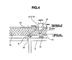
- Fig. 4 is a cross sectional view showing the vehicle interior panel including a skin molded by a core type die, taken along the line A-A in Fig. 1.
- Figs. 5A, 5B and 5C are explanatory views showing an embodiment of a weak portion of a back face of the skin member.
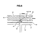
- Fig. 6 is a cross sectional view showing the weak portion of the skin member, taken along the line A-A in Fig. 1.
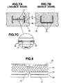
- Figs. 7A, 7B and 7C are explanatory views showing an embodiment of the weak portion of a back face of the skin member.
- Fig. 8 is a cross sectional view showing the weak portion of the skin member, taken along the line B-B in Fig. 1.
- Figs. 9A, 9B and 9C are cross sectional views for explaining tearing of a comparative vehicle interior panel during an airbag inflation.
- An important feature of the present invention resides in a position of a weak portion (functioning as a tearing portion) of a skin member of a vehicle interior panel, which functions as an airbag cover member constructed by a base member layer made of hard resin, a cushion layer laminated on the base member layer and a skin made of soft resin laminated on the cushion layer.
- a weak portion is conventionally formed at a position corresponding to a tearing portion of the base member layer. That is, the weak portion of the skin member is formed just above the tearing portion of the base member layer.
- a cushion layer is provided between a base member layer and a skin member, the cushion layer is compressed and the skin member is elongated due to the pushing-up of a door member during the inflation of an airbag.
- the weak portion is formed at a conventional position as same as that of the panel without a cushion layer, the tearing position of the skin member is shifted (offset) to a position outside of the weak portion, and the panel tends to be forcibly torn at a general position outside of the weak portion. Accordingly, the function of the weak portion for smoothly developing the airbag and opening the door portion becomes invalid, and the tearing surface of the panel becomes a rough surface due to such a forcible tearing.
- the weak portion is formed at a position outside of a conventional position upon taking account of an offset of the tearing planned position of the skin member, so as to prevent the above described problem from occurring and to naturally open the airbag cover body including the cushion layer of the vehicle interior panel.
- the offset quantity of the tearing planned position of the weak portion is positioned on an offset line which extends from the tearing portion of the base member layer while having an offset angle ranging from 15 through 7.0 degrees with respect to a line extending from the tearing portion of the base member layer in the vertically above direction, although the offset quantity of the tearing planned position is affected by materials of the respective layers of the airbag cover body, and particularly by the strength of the cushion layer and the tensile characteristic and the thickness of the skin member. It is further preferable that the offset angle of the offset line ranges from 34 through 65 degrees.
- the offset angle of the offset line with respect to the vertical line is smaller than 15 degrees, there is a possibility that the tearing of the skin member is generated at a position outside of the weak portion (tearing planned position) due to the shortage of the offset quantity of the weak portion. Therefore, in this case, it is difficult to sufficiently ensure the certainty and the reliability of the tearing performance of the airbag cover body.
- the offset angle of the offset line is greater than 70 degrees, there is a possibility that the actual tearing is generated at a position inside of the weak portion, and thus generating a forcible tearing of the airbag cover. This also becomes difficult to sufficiently ensure the certainty and the reliability of the tearing performance of the airbag cover body.
- an offset quantity necessary for properly tearing the airbag cover may be selected from a range having the offset angle ranging from 15 to 70 degrees upon taking account of the strength of the cushion layer and the tensile characteristic of the skin member.
- the offset angle is an angle defined by a line extending from the tearing portion of the base member layer in the thickness direction of the base member layer and a line connecting the tearing position of the base member layer and the weak portion of the skin member.
- the offset angle may be set at a small angle. In this case, by controlling the strength of the cushion layer, it becomes possible to further control the offset angle.
- the cushion layer when the cushion layer is molded from polyurethane foam by means of an reaction injection molding method and when a polyol, whose average molecular weight is small, is employed as a polyol, the cushion layer has a brittle characteristic. Accordingly, in this case, the offset angle may be set almost at 15 degrees, so that the weak portion of the skin is formed at a position immediately outside of the just above position of the tearing position of the base member layer. On the other hand, when a polyol, whose average molecular weight is large, is employed as a polyol, the strength of the cushion layer is increased. Accordingly, in this case, the offset angle may be set almost at 35 degrees so that the weak portion of the skin is formed at a position outside of the just above position of the tearing position of the base member layer.
- the offset angle may be set at a larger angle.
- the cushion layer is molded from polyurethane foam by means of a reaction injection molding method and when a polyol, whose average molecular weight is small, is employed as a polyol, the cushion layer has a brittle characteristic. Accordingly, in this case, the offset angle may be set almost at 60 degrees.
- the offset angle may be set almost at 70 degrees. That is, it is possible to select the offset angle of the weak portion of the skin according to the tensile of the material of the skin member and the strength of the cushion layer.
- the weak portion which is formed at the above-discussed offset position, is constructed as follows, in view of further improving the reliability of the tearing of the door portion.
- the weak portion formed in the skin member is formed at a thick portion of the skin member. Further it is preferable that the thick portion of the skin member is formed into a trapezoid in cross section so as to gradually rise from both sides toward a top.
- the vehicle interior panel according to the present invention is constructed by the base member layer, the cushion layer laminated on the base member layer and the skin laminated on the cushion layer.
- the base member layer has a thickness ranging from 2.5 to 4.0 mm, and is molded from relatively hard material such as PPC resin, which is obtained by reinforcing polypropylene by talc or the like, by means of the injection molding method.
- PPC resin polypropylene
- talc or the like polymer alloy of poly carbonate and ABS resin
- maleimide resin SMA: styrene maleic anhydride copolymer
- denatured polyphenylene oxide may be selected.
- the cushion layer has a thickness ranging from 5 to 10 mm and is molded from foaming material such as urethane foam by means of the reaction injection molding method.
- the skin member laminated on the base member layer is molded from soft polyurethane resin having a preferable texture by means of the reaction injection molding method.
- the material of the skin member is not limited to the polyurethane, and may be other resin having a soft and preferable texture.
- a general portion of the skin member has a thickness ranging from 0.5 to 1.0 mm, the weak portion acting as a tearing planned portion is formed at a thick portion which is thicker than the general portion, and the thick portion has a trapezoidal cross section cut along the lateral direction.
- the width of the thick portion ranges from 6 to 15 mm, and more preferably ranges from 8 to 10 mm.
- the width of a top portion of the thick portion ranges from 2.5 to 6.0 mm, and more preferably ranges from 4 to 5 mm.
- the thickness of the top portion ranges from 2 to 5 mm, and more preferably ranges from 3.5 to 4.5 mm.
- a groove width or groove diameter of the weak portion ranges from 0.3 to 2.0 mm, and more preferably, it is a slot or a plurality of holes having a width ranging from 0.5 to 1.5 mm.
- a remaining thickness of the skin at a bottom portion of the groove portion it is preferable that the remaining thickness ranges from 0.3 to 1.0 mm, and more preferably ranges from 0.5 to 0.8 mm.
- the weak portion has a two step structure, that is, a second weak part of a tapered tip is formed at a bottom end of a first weak part formed into a continuous groove. It is preferable that the second weak part is selectively formed into a continuous groove or discontinuous grooves according to the applied portion. For example, it is preferable that the second weak part at a crossing position of the tearing planned portions is formed into a continuous groove so as to smoothly execute a tearing at the tearing planned portion.
- the polyurethane resin material for the skin member has a low viscosity performing a high flowability and has a small shrinkage ratio. Further it is preferable that the skin member is molded using such material by means of an injection molding or reaction injection molding.
- the molding of the cushion layer is executed by setting (inserting) the base member layer and the skin member in a cushion molding die and by injecting the material of the cushion layer into a space between the base member layer and the skin member. It is preferable that the material fills an inner portion of the depressed portion of the skin member during the molding so that the cushion layer is formed at the depressed portion.
- the cross-section of the thick portion along the lateral direction is formed into a trapezoidal shape according to the present invention, it becomes possible to further certainly prevent the skin member having the characteristic of soft, thin and low strength from tearing over the tearing planned portion and toward a range outside the tearing planned portion.
- the weak portion functioning as the braking planned portion is formed according to the shape of the door portion of the airbag apparatus. Therefore, in case of a single door, the weak portion is formed into a U-shape (spade-lug shape), and in case of double doors, the weak portion is formed into H-shape.
- Fig. 1 is a perspective view showing a vehicle interior panel of the present invention, which is integrated with an airbag apparatus.
- Figs. 2A, 2B and 2C are cross sectional views taken along the line A-A in Fig. 1 and explanatory views for explaining the condition of the vehicle interior panel during the operation of the airbag apparatus. More specifically, Fig. 2A shows a normal condition.
- Fig. 2B shows a pushed condition in that an expanding airbag pushes up the vehicle interior panel, the cushion layer receives a compression force and a tensile force, and the skin receives the tensile force.
- Fig. 2C shows a tearing condition in that the cushion layer and the skin member are torn at the weak portion functioning as a tearing planned portion due to the push-up of the airbag.
- Fig. 3 shows a die (core side die) for molding the skin member employed in the vehicle interior panel according to the present invention.
- Fig. 4 shows an embodiment of the vehicle interior panel which comprises the skin molded using the die shown in Fig. 3, and is a cross sectional view, taken along the line A-A in Fig. 1, for explaining the weak portion of the skin in detail.
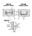
- Figs. 5A, 5B and 5C are explanatory views for explaining a structure of a back surface of the skin of the vehicle interior panel according to the present invention.
- Fig. 5A shows a shape of the weak portion of the skin member applied to a double-door type vehicle interior panel.
- Fig. 5B shows a shape of the weak portion of the skin member applied to a single-door type vehicle interior panel.
- Fig. 5A shows a shape of the weak portion of the skin member applied to a double-door type vehicle interior panel.
- Fig. 5B shows a shape of the weak portion of the skin member applied to a single-door type
- FIG. 5C shows a detailed structure of the weak portion at a circle (crossing portion) in Fig. 5A.
- a crossing portion of the weak proportion is constructed by a continuous groove.
- Fig. 6 is also a cross sectional view, taken along the line A-A in Fig. 1, for explaining the weak portion of the skin member in detail.
- Figs. 7A, 7B and 7C are also explanatory views for explaining a structure of a back surface of the skin member of the vehicle interior panel according to the present invention.
- Fig. 7C shows a detailed structure of the weak portion at a circle (crossing portion) in Fig. 7A.
- a center portion of the weak portion is constructed by a continuous groove.
- Fig. 8 is a cross sectional view taken along the line B-B in Fig. 1 and is an explanatory view for explaining the structure of the back surface of the weak portion of the skin member.
- reference numeral 1 denotes a vehicle interior panel
- 2 a soft resin inner (a supporting member of a door portion), 3 a door portion, 4 a door reinforcing portion, 5 a hinge portion, 6 a skin tearing planned line, 9 a tearing portion of a base member layer, 10 a connecting portion, 11 a retainer fixing hole, 12 an outer peripheral portion of the soft resin inner, 13 a skin member, 14 a hard resin base member layer, 15 a cushion layer, 16 a discontinuous groove portion, 17 a continuous groove portion, and 18 a skin thick portion.
- the vehicle interior panel 1 comprises the base member layer 14 made of hard resin, the cushion layer 15 made of plastic foam such as polyurethane foam, and the skin member 13. More specifically, the vehicle interior panel 1 constructed by laminating the cushion layer 15 on the base member layer 14 and by further laminating the skin member 13 on the cushion layer 15.
- the door reinforcing portion 4 and the supporting portion 2 of the door portion 3, which are connected through the hinge portion 5, are connected to a back surface of the base member layer 14 of the vehicle interior panel 1.
- the skin member 13 comprises the thick portion 18 at which the tearing planed portion (tearing planned line) 6 is formed.
- the tearing planned portion (weak portion) 6 is constructed by the discontinuous groove portion 16 and the continuous groove portion 17.
- the thick portion 18 including the weak portion 6 is formed outside of a position just above the tearing portion 9 of the base member layer 14. More specifically, at both sides of an H-shaped weak portion 6 of a double door type is outwardly offset from the position just above the tearing portion 9 of the base member layer 14.
- the weak portion 6 of the skin member 13 is offset from the just above position of the braking planned portion 9 of the base member layer 14 toward the outside thereof upon taking account a situation that the position at which the skin member 13 stretches and tears as shown in Figs. 2A through 2C. That is, the weak portion 6 is formed at a position according to the offset of the tearing of the cushion layer. This prevents the separation between the skin member 13 and the cushion layer 15. which is caused by the stretching separation, and enables the vehicle interior panel 1 functioning as an airbag cover to be smoothly broken along the weak portion 6 of the skin member 13 as planned.
- the weak portion of the skin member is formed at a position corresponding to the breaking portion of the base member layer as shown in Figs. 9A through 9C which show a related art of the vehicle interior panel functioning as an airbag cover, that is, when the weak portion is formed at a position just above the tearing portion of the base member layer, the skin member is stretched and deformed due to the pushing-up of the door portions while resisting the tearing of the skin member. Therefore, the skin member is forcibly torn at a position outside of the weak portion (tearing planned portion) due to the influence of the stretch of the skin member, except for the weak portion of the tearing planned portion. Therefore, the cushion layer constructed by a foamed member having a small tensile characteristic is separated from the skin member and is broken into pieces.
- the vehicle interior panel 1 shown in Fig. 1 in accordance with the embodiment of the present invention shown in Fig. 1 is produced as follows.
- the skin member 13 is molded by the injection molding or reaction injection molding using a die arranged to form a tearing planned portion in the skin member 13.
- the employed die corresponds to the structure of the weak portion 6 of the skin member 13 as shown in Fig. 3, and comprises a depress portion corresponding to the trapezoidal thick portion, a thin-wall protruding portion continuously formed at the center portion corresponding to the groove portion, and a tip end pins or a second groove, which are formed on the protruding portion.
- the skin member 13 according to the present invention includes a very thin portion and is produced using the die shown in Fig. 3 and using polyurethane material
- the viscosity of the used polyurethane material is in a range from 500 to 1000 centipoises under a melted condition in an injection molding machine including the molding die.
- the shrinkage ratio after the molding is small as possible.
- the shrinkage ratio of the selected material is in a range from 3/10000 to 8/10000.
- a specific gravity of the material for the skin member 13 is 0.8 or more, the material is non-foaming or very little foaming characteristic, and the tensile strength thereof is 70 kgf/cm 2 or less.
- the elongation of the material for the skin member 13 ranges from 150 to 400 %, and more preferable that it ranges from 150 to 250 %.
- the measurements of the tensile load and the elongation of the material for the skin member 13 were on the basis of JIS K 6301 (Japanese Industrial Standard).
- the skin member 13 of the vehicle interior panel 1 which was actually used in the experiment of developing an airbag, had a characteristic that an elongation characteristic at room temperature was 210 %, and the tensile strength was 30 kgf/cm 2 .
- the base member layer 14 is produced by injection molding using polypropylene adding talc as a filler. Finally, by inserting the skin member 13 and the base member layer 14 in the die and by injecting polyurethane foam between the skin member 13 and the base member layer 14. the cushion layer 15 is molded, and therefore the vehicle interior panel 1 showing in Fig. 1 is produced.
- the vehicle interior panel according to the embodiment of the present embodiment has been shown and described such that the weak portion 6 is formed on the cushion-layer-side surface of the skin member 13, which faces with the cushion layer 15, the invention is not limited to this, and the weak portion 6 may be formed on an outer surface of the skin member 13, which faces with a passenger compartment, or may be formed on a cushion-layer-side surface of the base member layer 14, which faces with the cushion layer 15.
Landscapes
- Engineering & Computer Science (AREA)
- Mechanical Engineering (AREA)
- Air Bags (AREA)
- Instrument Panels (AREA)
Applications Claiming Priority (1)
| Application Number | Priority Date | Filing Date | Title |
|---|---|---|---|
| JP2005180040A JP4820473B2 (ja) | 2005-06-21 | 2005-06-21 | 自動車用内装パネル |
Publications (3)
| Publication Number | Publication Date |
|---|---|
| EP1736377A2 true EP1736377A2 (de) | 2006-12-27 |
| EP1736377A3 EP1736377A3 (de) | 2008-03-26 |
| EP1736377B1 EP1736377B1 (de) | 2009-11-18 |
Family
ID=37068215
Family Applications (1)
| Application Number | Title | Priority Date | Filing Date |
|---|---|---|---|
| EP06012632A Not-in-force EP1736377B1 (de) | 2005-06-21 | 2006-06-20 | Fahrzeuginnenplatte |
Country Status (4)
| Country | Link |
|---|---|
| US (1) | US7673896B2 (de) |
| EP (1) | EP1736377B1 (de) |
| JP (1) | JP4820473B2 (de) |
| DE (1) | DE602006010479D1 (de) |
Families Citing this family (11)
| Publication number | Priority date | Publication date | Assignee | Title |
|---|---|---|---|---|
| JP4906551B2 (ja) * | 2007-03-20 | 2012-03-28 | ダイキョーニシカワ株式会社 | エアバッグドア部構造 |
| FR2916175B1 (fr) * | 2007-05-16 | 2009-11-27 | Faurecia Interieur Ind | Element d'habillage de l'interieur d'un vehicule automobile. |
| US20110062687A1 (en) * | 2008-05-19 | 2011-03-17 | Kanto Auto Works, Ltd. | Automobile airbag door and process for producing the same |
| JPWO2010024300A1 (ja) | 2008-08-26 | 2012-01-26 | 国立大学法人北海道大学 | 骨充填型軟骨組織再生誘導剤 |
| JP6020277B2 (ja) | 2012-10-22 | 2016-11-02 | 豊田合成株式会社 | 車両用内装パネル及び車両用エアバッグ装置 |
| US8967659B2 (en) * | 2013-03-14 | 2015-03-03 | Inteva Products, Llc | Panel with integral hidden door cover and method of manufacture and materials thereof |
| KR20140115654A (ko) * | 2013-03-21 | 2014-10-01 | 현대모비스 주식회사 | 자동차 에어백 |
| DE102015208823A1 (de) * | 2015-05-12 | 2016-11-17 | Faurecia Innenraum Systeme Gmbh | Fahrzeug-Innenverkleidungsteil zum Abdecken eines Airbags und Herstellungsverfahren |
| KR102408193B1 (ko) * | 2018-01-24 | 2022-06-13 | 현대모비스 주식회사 | 조수석 에어백 도어 |
| US10780843B2 (en) * | 2018-01-30 | 2020-09-22 | Toyota Motor Engineering & Manufacturing North America, Inc. | Methods for forming and tuning the durability of breakaway sections on a trim panel |
| EP4023503B1 (de) * | 2020-10-12 | 2023-12-06 | Hyundai Mobis Co., Ltd. | Fahrzeug-crashpad mit airbag klappe |
Family Cites Families (34)
| Publication number | Priority date | Publication date | Assignee | Title |
|---|---|---|---|---|
| US4991870A (en) * | 1989-08-28 | 1991-02-12 | Tip Engineering Group, Inc. | Method and arrangement for forming an air bag deployment opening in an auto interior trim piece |
| US5082310A (en) * | 1989-11-06 | 1992-01-21 | Tip Engineering Group, Inc. | Arrangement for providing an air bag deployment opening |
| JP3006069B2 (ja) * | 1990-10-26 | 2000-02-07 | タカタ株式会社 | エアバッグ装置のモジュールカバー |
| US5154444A (en) * | 1991-04-05 | 1992-10-13 | Davidson Textron Inc. | Air bag retainer with cutting flaps |
| DE4229565C2 (de) * | 1992-09-04 | 1995-05-18 | Daimler Benz Ag | Insassenrückhaltesystem mit einem Gassack |
| JP3185515B2 (ja) * | 1994-02-17 | 2001-07-11 | 豊田合成株式会社 | エアバッグ装置のパッド |
| US5447328A (en) * | 1994-05-31 | 1995-09-05 | Davidson Textron | Trim panel having integral door cover |
| JP3201243B2 (ja) * | 1995-12-12 | 2001-08-20 | 豊田合成株式会社 | エアバッグ用蓋体付き自動車内装品 |
| DE19646548C2 (de) * | 1996-10-31 | 1998-08-27 | Sommer Allibert Lignotock Gmbh | Innenverkleidungsteil für Kraftfahrzeuge mit Airbag-Ausrüstung |
| AU749401B2 (en) * | 1997-02-19 | 2002-06-27 | Toyo Tire & Rubber Co., Ltd. | Instrument panel for air bag |
| US5997030A (en) * | 1997-03-19 | 1999-12-07 | Lear Automotive Dearborn, Inc. | Vehicle instrument panel with seamless airbag cover |
| EP0904994B1 (de) | 1997-03-26 | 2009-05-13 | Toyota Jidosha Kabushiki Kaisha | Innenfahrzeugteile mit einer airbagaustrittsklappe und giessmethode dafür |
| JPH1134781A (ja) * | 1997-07-16 | 1999-02-09 | Toyo Tire & Rubber Co Ltd | エアバッグ装置用インストルメントパネルとその製造方法 |
| DE19800815C1 (de) * | 1998-01-05 | 1999-02-04 | Sommer Allibert Lignotock Gmbh | Verfahren zur Einarbeitung einer unsichtbaren Reißnaht in mit Schaumstoff hinterlegte Kaschierungsfolien |
| JP3298503B2 (ja) * | 1998-04-28 | 2002-07-02 | トヨタ自動車株式会社 | エアバッグドア部を有する車両用内装部材 |
| US5961143A (en) * | 1998-05-11 | 1999-10-05 | Textron Automotive Company | Motor vehicle air bag cover having a skin with perforated score line and a method for manufacture thereof |
| JP3321560B2 (ja) * | 1998-11-16 | 2002-09-03 | 株式会社イノアックコーポレーション | エアバッグドア部の構造 |
| JP3370044B2 (ja) * | 1999-06-03 | 2003-01-27 | 東海化成工業株式会社 | 表皮及びその製造方法と、エアバッグドア用表皮の製造方法及びエアバッグドア構造 |
| DE29911205U1 (de) * | 1999-06-18 | 1999-08-12 | SOMMER ALLIBERT-LIGNOTOCK GmbH, 76744 Wörth | Sicherheitsabdeckung für einen Airbag |
| JP2001158318A (ja) * | 1999-09-20 | 2001-06-12 | Mitsuboshi Belting Ltd | エアバッグ用インストルメントパネル |
| JP2001088646A (ja) * | 1999-09-22 | 2001-04-03 | Mitsuboshi Belting Ltd | エアバッグドア構造 |
| US6402189B1 (en) * | 2000-02-15 | 2002-06-11 | Textron Automotive Company, Inc | Airbag door and method for making same |
| US6709007B2 (en) * | 2000-02-15 | 2004-03-23 | Collins & Aikman Automotive Company Inc. | Airbag door and method for making same |
| JP2002127860A (ja) * | 2000-10-25 | 2002-05-09 | Nishikawa Kasei Co Ltd | 自動車のエアバッグドア部付内装品 |
| JP3727248B2 (ja) * | 2001-03-13 | 2005-12-14 | 西川化成株式会社 | エアバッグドアの表皮材 |
| CN1582237A (zh) * | 2001-10-23 | 2005-02-16 | 通用电气公司 | 带有隐藏的气囊门的仪表板系统 |
| JP3787517B2 (ja) * | 2001-11-22 | 2006-06-21 | 西川化成株式会社 | エアバッグドア付車両用内装品 |
| US7100941B2 (en) * | 2003-02-24 | 2006-09-05 | Collins & Aikman | Pre-weakening of fabric covered airbag doors |
| JP2005008057A (ja) * | 2003-06-19 | 2005-01-13 | Inoac Corp | エアバッグドアの開放構造 |
| DE602004014574D1 (de) * | 2003-09-30 | 2008-08-07 | Nihon Plast Co Ltd | Gassackabdeckung und Herstellungsverfahren dafür |
| JP4215612B2 (ja) * | 2003-09-30 | 2009-01-28 | 日本プラスト株式会社 | 自動車用内装パネル |
| US7237797B2 (en) * | 2003-10-24 | 2007-07-03 | Visteon Global Technologies, Inc. | Instrument panel having modular airbag door assembly |
| US7093850B2 (en) * | 2003-11-14 | 2006-08-22 | Delphi Technologies, Inc. | Instrument panel with integral hidden door cover and method of manufacture thereof |
| US7275759B2 (en) * | 2005-03-08 | 2007-10-02 | Takata Corporation | Cover for use in airbag apparatus, and airbag apparatus |
-
2005
- 2005-06-21 JP JP2005180040A patent/JP4820473B2/ja not_active Expired - Fee Related
-
2006
- 2006-06-20 EP EP06012632A patent/EP1736377B1/de not_active Not-in-force
- 2006-06-20 DE DE602006010479T patent/DE602006010479D1/de not_active Expired - Fee Related
- 2006-06-20 US US11/455,697 patent/US7673896B2/en not_active Expired - Fee Related
Also Published As
| Publication number | Publication date |
|---|---|
| JP4820473B2 (ja) | 2011-11-24 |
| EP1736377B1 (de) | 2009-11-18 |
| DE602006010479D1 (de) | 2009-12-31 |
| EP1736377A3 (de) | 2008-03-26 |
| JP2007001320A (ja) | 2007-01-11 |
| US20060284401A1 (en) | 2006-12-21 |
| US7673896B2 (en) | 2010-03-09 |
Similar Documents
| Publication | Publication Date | Title |
|---|---|---|
| JP3298503B2 (ja) | エアバッグドア部を有する車両用内装部材 | |
| EP1520754B1 (de) | Gassackabdeckung und Herstellungsverfahren dafür | |
| EP1736377B1 (de) | Fahrzeuginnenplatte | |
| JP2001088646A (ja) | エアバッグドア構造 | |
| CN103402827A (zh) | 用于气囊覆盖层的成角的撕裂缝 | |
| US7458604B2 (en) | Automotive trim assembly having an integrated airbag door | |
| US6260875B1 (en) | Seamless/integral DSIR or PSIR door configuration in hard plastic trim application facilitated by gas | |
| EP1013515B1 (de) | Autoinnenteil mit Airbagabdeckungsteil | |
| JPH09226413A (ja) | インストルメントパネル及びインストルメントパネルの成形方法 | |
| US20060082109A1 (en) | Method of making an automotive trim assembly having an integrated airbag door | |
| JPH09301013A (ja) | エアバッグドアを一体に有する車室側部材の構造 | |
| JPH1142998A (ja) | エアバッグドア部を有する車両用内装部材 | |
| JPH0952567A (ja) | エアバッグドアを備えたインストルメントパネル | |
| JP4215612B2 (ja) | 自動車用内装パネル | |
| JP3428345B2 (ja) | エアバッグドアを一体に有するインストルメントパネル及びその製造方法 | |
| JP3916951B2 (ja) | エアバッグドア | |
| JP3417295B2 (ja) | エアバッグドア部を有する車両用内装部材 | |
| JP2000177525A (ja) | エアバッグドアの構造及びエアバッグドアの製造方法 | |
| JP2849078B2 (ja) | エアバッグドアを一体に有するインストルメントパネル | |
| JP2003200804A (ja) | エアバッグドア一体型インストルメントパネル | |
| JP4363634B2 (ja) | エアバッグカバー | |
| JP2003154915A (ja) | エアバッグドア | |
| JP4668669B2 (ja) | 自動車用内装パネル | |
| US20240034262A1 (en) | Instrument panel airbag assembly | |
| JPH1178751A (ja) | エアバッグ装置のエアバッグドア |
Legal Events
| Date | Code | Title | Description |
|---|---|---|---|
| PUAI | Public reference made under article 153(3) epc to a published international application that has entered the european phase |
Free format text: ORIGINAL CODE: 0009012 |
|
| 17P | Request for examination filed |
Effective date: 20060620 |
|
| AK | Designated contracting states |
Kind code of ref document: A2 Designated state(s): AT BE BG CH CY CZ DE DK EE ES FI FR GB GR HU IE IS IT LI LT LU LV MC NL PL PT RO SE SI SK TR |
|
| AX | Request for extension of the european patent |
Extension state: AL BA HR MK YU |
|
| PUAL | Search report despatched |
Free format text: ORIGINAL CODE: 0009013 |
|
| AK | Designated contracting states |
Kind code of ref document: A3 Designated state(s): AT BE BG CH CY CZ DE DK EE ES FI FR GB GR HU IE IS IT LI LT LU LV MC NL PL PT RO SE SI SK TR |
|
| AX | Request for extension of the european patent |
Extension state: AL BA HR MK YU |
|
| 17Q | First examination report despatched |
Effective date: 20080604 |
|
| AKX | Designation fees paid |
Designated state(s): DE FR GB |
|
| GRAP | Despatch of communication of intention to grant a patent |
Free format text: ORIGINAL CODE: EPIDOSNIGR1 |
|
| GRAS | Grant fee paid |
Free format text: ORIGINAL CODE: EPIDOSNIGR3 |
|
| GRAA | (expected) grant |
Free format text: ORIGINAL CODE: 0009210 |
|
| AK | Designated contracting states |
Kind code of ref document: B1 Designated state(s): DE FR GB |
|
| REG | Reference to a national code |
Ref country code: GB Ref legal event code: FG4D |
|
| REF | Corresponds to: |
Ref document number: 602006010479 Country of ref document: DE Date of ref document: 20091231 Kind code of ref document: P |
|
| PLBE | No opposition filed within time limit |
Free format text: ORIGINAL CODE: 0009261 |
|
| STAA | Information on the status of an ep patent application or granted ep patent |
Free format text: STATUS: NO OPPOSITION FILED WITHIN TIME LIMIT |
|
| 26N | No opposition filed |
Effective date: 20100819 |
|
| GBPC | Gb: european patent ceased through non-payment of renewal fee |
Effective date: 20100620 |
|
| REG | Reference to a national code |
Ref country code: FR Ref legal event code: ST Effective date: 20110228 |
|
| PG25 | Lapsed in a contracting state [announced via postgrant information from national office to epo] |
Ref country code: DE Free format text: LAPSE BECAUSE OF NON-PAYMENT OF DUE FEES Effective date: 20110101 |
|
| PG25 | Lapsed in a contracting state [announced via postgrant information from national office to epo] |
Ref country code: FR Free format text: LAPSE BECAUSE OF NON-PAYMENT OF DUE FEES Effective date: 20100630 |
|
| PG25 | Lapsed in a contracting state [announced via postgrant information from national office to epo] |
Ref country code: GB Free format text: LAPSE BECAUSE OF NON-PAYMENT OF DUE FEES Effective date: 20100620 |