EP1736631A2 - Roller shutter box - Google Patents
Roller shutter box Download PDFInfo
- Publication number
- EP1736631A2 EP1736631A2 EP06009855A EP06009855A EP1736631A2 EP 1736631 A2 EP1736631 A2 EP 1736631A2 EP 06009855 A EP06009855 A EP 06009855A EP 06009855 A EP06009855 A EP 06009855A EP 1736631 A2 EP1736631 A2 EP 1736631A2
- Authority
- EP
- European Patent Office
- Prior art keywords
- roller shutter
- tank inlet
- shutter box
- inlet
- armoured
- Prior art date
- Legal status (The legal status is an assumption and is not a legal conclusion. Google has not performed a legal analysis and makes no representation as to the accuracy of the status listed.)
- Withdrawn
Links
- 238000007689 inspection Methods 0.000 claims description 8
- 239000011505 plaster Substances 0.000 claims description 6
- 241000238631 Hexapoda Species 0.000 description 1
- 235000004443 Ricinus communis Nutrition 0.000 description 1
- 240000000528 Ricinus communis Species 0.000 description 1
- 230000006978 adaptation Effects 0.000 description 1
- 238000006073 displacement reaction Methods 0.000 description 1
- 238000009434 installation Methods 0.000 description 1
- 230000000475 sunscreen effect Effects 0.000 description 1
- 239000000516 sunscreening agent Substances 0.000 description 1
Images

Classifications
-
- E—FIXED CONSTRUCTIONS
- E06—DOORS, WINDOWS, SHUTTERS, OR ROLLER BLINDS IN GENERAL; LADDERS
- E06B—FIXED OR MOVABLE CLOSURES FOR OPENINGS IN BUILDINGS, VEHICLES, FENCES OR LIKE ENCLOSURES IN GENERAL, e.g. DOORS, WINDOWS, BLINDS, GATES
- E06B9/00—Screening or protective devices for wall or similar openings, with or without operating or securing mechanisms; Closures of similar construction
- E06B9/02—Shutters, movable grilles, or other safety closing devices, e.g. against burglary
- E06B9/08—Roll-type closures
- E06B9/11—Roller shutters
- E06B9/17—Parts or details of roller shutters, e.g. suspension devices, shutter boxes, wicket doors, ventilation openings
- E06B9/17007—Shutter boxes; Details or component parts thereof
Definitions
- the invention relates to a roller shutter box with a tank inlet attached to the head piece in a receptacle with an additional receptacle for a fly screen or another roller blind, and a revision cover and a frame connection profile.
- Roller shutter boxes of the designated type are known per se.
- the same applies to the shutter box gem. of the EP 0 843 067 A2 Again, no possibility is shown to use wider, narrower or split roller shutter.
- the invention as described in the claims, therefore has the object to remedy the disadvantages of the known roller shutter boxes and to have a roller shutter box whose tank inlet of different dimensions, such as. different widths, but also one or more times divided tanks is customizable
- an inspection cover which has a grid with the frame connection profile instead of a screw, which facilitates its installation, opening and closing considerably
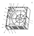
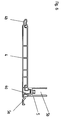
- the head piece 1 is equipped with a receptacle 1 a for the tank inlet 2, which has a guide and fastening tab 2a and a receptacle 2b for an additional roller blind, such as sunscreen, insect screen or the like there is an outer panel 3 with a guide groove 3a for the attachment tab 2a of the tank inlet.
- the roller shutter box has right below a revision cover 4, which is fixed by means of a detent 4a in the plaster rail 5 and a detent 4b in the frame connection profile 8 An additional screw connection of the inspection cover 4 is not required.
- 5a with a locking groove for the inspection cover 4 and 5b is designated for such a connection for the inspection cover with the plaster base plate 6
- a connecting profile 7 is used to connect the outer panel 3 with the opposite plaster base plate 6.
- the center bearing is designated 9
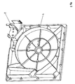
- FIG. 2 shows the tank inlet 2, which is attached to the head piece 1 in the receptacle 1 a wherein the same is shown below left
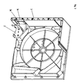
- the figure 3 shows that the tank inlet 2 in the guide groove 3a of the outer panel 3 is slidably mounted on each position and with the guiding and fastening tab 2a of the tank inlet 2 on the outer panel 3 of the roller shutter box 1
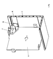
- FIG. 4 A variant embodiment is shown in Figure 4 There, the tank inlet 2 is fixed on both sides of the center bearing 9 of the head piece 1
Landscapes
- Engineering & Computer Science (AREA)
- Structural Engineering (AREA)
- Architecture (AREA)
- Civil Engineering (AREA)
- Operating, Guiding And Securing Of Roll- Type Closing Members (AREA)
- Catching Or Destruction (AREA)
- Electroplating Methods And Accessories (AREA)
- Manufacture And Refinement Of Metals (AREA)
- Closures For Containers (AREA)
Abstract
Description
Die Erfindung betrifft einen Rollladenkasten mit einem am Kopfstück in einer Aufnahme befestigten Panzereinlauf mit einer zusätzlichen Aufnahme für einen Fliegenschutz- oder einen anderen Rollo, sowie einem Revisionsdeckel und einem Rahmenanschlussprofil.The invention relates to a roller shutter box with a tank inlet attached to the head piece in a receptacle with an additional receptacle for a fly screen or another roller blind, and a revision cover and a frame connection profile.
Rollladenkästen der bezeichneten Art sind an sich bekannt So zeigt beispielsweise die
Der Erfindung, wie sie in den Ansprüchen beschrieben ist, liegt daher die Aufgabe zugrunde, die Nachteile der bekannten Rollladenkästen zu beheben und einen Rollladenkasten zu besitzen, dessen Panzereinlauf unterschiedlichen Abmessungen, wie z.B. unterschiedlichen Breiten, aber auch ein- oder mehrfach geteilten Panzern anpassbar istThe invention, as described in the claims, therefore has the object to remedy the disadvantages of the known roller shutter boxes and to have a roller shutter box whose tank inlet of different dimensions, such as. different widths, but also one or more times divided tanks is customizable
Die mit der Erfindung erzielten Vorteile sind einerseits eine einfache, unproblematische Montage, die einfache Verschiebung und Anpassung der Breite des Rolliadenpanzereinlaufs an unterschiedliche Rollladenpanzer - selbst auf der Baustelle und andererseits die mögliche Anpassung bzw. auch Teilung des Einlaufs an einen oder auch mehrere Panzer. Zusätzlich ist ein Revisionsdeckel vorgesehen, der statt einer Verschraubung eine Rasterung mit dem Rahmenanschlussprofil aufweist, was dessen Montage, öffnen und Schließen erheblich erleichtertThe advantages achieved by the invention are on the one hand a simple, unproblematic assembly, the simple displacement and adjustment of the width of the roller shutter tank inlet to different roller shutter - even on site and on the other hand, the possible adaptation or division of the inlet to one or more tanks. In addition, an inspection cover is provided, which has a grid with the frame connection profile instead of a screw, which facilitates its installation, opening and closing considerably
Die Erfindung ist nachstehend anhand eines in den Abbildungen dargestellten Ausführungsbeispieles näher erläutertThe invention is explained below with reference to an embodiment shown in the drawings
Es zeigt
- Fig. 1: eine perspektivische Darstellung des Kopfstückes eines erfindungsgemäßen Rollladenkastens,
- Fig. 2: eine ebensolche Darstellung des Panzereinlaufs,
- Fig. 3: eine Ausführungsvariante der Fig. 1 und 2,
- Fig. 4: eine weitere Ausführungsvariante,
- Fig. 5: den Revisionsdeckel und
- Fig. 6: die Rasten für den Revisionsdeckel.
- 1 is a perspective view of the head piece of a roller shutter box according to the invention,
- 2: a similar representation of the tank inlet,
- 3 shows an embodiment of FIGS. 1 and 2,
- 4 shows a further embodiment variant,
- Fig. 5: the inspection cover and
- Fig. 6: the detents for the inspection cover.
Wie in den Abbildungen dargestellt, ist das Kopfstück 1 mit einer Aufnahme 1 a für den Panzereinlauf 2 ausgerüstet, die eine Führungs- und Befestigungslasche 2a und eine Aufnahme 2b für ein zusätzliches Rollo, wie beispielsweise Lichtschutz-, Insektenschutzrollo oder dergl. besitzt Ferner befindet sich dort eine Außenblende 3 mit einer Führungsnut 3a für die Befestigungslasche 2a des Panzereinlaufs.As shown in the figures, the
Der Rollladenkasten besitzt rechts unten einen Revisionsdeckel 4, der mittels einer Raste 4a in der Putzschiene 5 und einer Raste 4b im Rahmenanschlussprofil 8 befestigt ist Eine zusätzliche Verschraubung des Revisionsdeckels 4 ist nicht erforderlich. Mit 5a ist eine Rastnut für den Revisionsdeckel 4 und mit 5b eine solche für die Verbindung des Revisionsdeckels mit der Putzträgerplatte 6 bezeichnetThe roller shutter box has right below a
Ein Verbindungsprofil 7 dient zur Verbindung der Außenblende 3 mit der gegenüberliegenden Putzträgerplatte 6. Das Mittellager ist mit 9 bezeichnetA connecting
Die Figur 2 zeigt den Panzereinlauf 2, der am Kopfstück 1 in der Aufnahme 1 a befestigt ist wobei derselbe unten links dargestellt istFigure 2 shows the
Die Figur 3 lässt erkennen, dass der Panzereinlauf 2 in der Führungsnut 3a der Außenblende 3 auf jede Position verschiebbar und mit der Führungs- und Befestigungslasche 2a des Panzereinlaufs 2 an der Außenblende 3 des Rollladenkastens 1 befestigt istThe figure 3 shows that the
Eine Ausführungsvariante ist in der Figur 4 dargestellt Dort ist der Panzereinlauf 2 beidseitig vom Mittellager 9 des Kopfstückes 1 befestigt A variant embodiment is shown in Figure 4 There, the
- 1.1.
- Kopfstück,Headpiece
- 2.Second
- Panzereinlauf,Tank inlet,
- 3.Third
- Außenblende,Outer panel,
- 4.4th
- Revisionsdeckel,Inspection cover,
- 5.5th
- Putzschiene,Plaster splint,
- 6.6th
- Putzträgerplatte,Plaster baseboard,
- 7.7th
- Verbindungsprofil,Connection Profile,
- 8.8th.
- Rahmenanschlussprofil,Frame connection profile,
- 9.9th
- Mittellagercenter bearing
- 1 a.1 a.
-
Aufnahme für Panzereinlauf 2,Intake for
tank inlet 2, - 2a.2a.
- Führungs- und Befestigungslasche,Guide and fastening strap,
- 3a.3a.
- Führung für Befestigungslasche 2a,Guide for fastening tab 2a,
- 4a.4a.
- Raste,racing,
- 5a.5a.
- Rastnut,locking groove,
- 2b.2 B.
- Aufnahme für RolloShooting for roller blind
- 4b.4b.
- Raste,racing,
- 5b.5b.
- Rastnut,locking groove,
Claims (3)
Applications Claiming Priority (1)
| Application Number | Priority Date | Filing Date | Title |
|---|---|---|---|
| DE102005029578A DE102005029578B4 (en) | 2005-06-25 | 2005-06-25 | Shutter box |
Publications (2)
| Publication Number | Publication Date |
|---|---|
| EP1736631A2 true EP1736631A2 (en) | 2006-12-27 |
| EP1736631A3 EP1736631A3 (en) | 2007-06-13 |
Family
ID=37027683
Family Applications (1)
| Application Number | Title | Priority Date | Filing Date |
|---|---|---|---|
| EP06009855A Withdrawn EP1736631A3 (en) | 2005-06-25 | 2006-05-12 | Roller shutter box |
Country Status (7)
| Country | Link |
|---|---|
| US (1) | US20060289120A1 (en) |
| EP (1) | EP1736631A3 (en) |
| CN (1) | CN1884783A (en) |
| CA (1) | CA2549991A1 (en) |
| DE (1) | DE102005029578B4 (en) |
| RU (1) | RU2321715C1 (en) |
| UA (1) | UA83399C2 (en) |
Cited By (5)
| Publication number | Priority date | Publication date | Assignee | Title |
|---|---|---|---|---|
| EP1811120A1 (en) * | 2006-01-19 | 2007-07-25 | Veka AG | Roller shutter housing for mounting on a blind frame |
| EP1953331A1 (en) * | 2007-02-01 | 2008-08-06 | REHAU AG + Co | Housing for a roller shutter box and roller shutter box with such a housing |
| EP1775415A3 (en) * | 2005-10-13 | 2010-02-03 | Veka AG | Roller shutter box |
| EP2182162A2 (en) | 2008-11-03 | 2010-05-05 | Profine Gmbh | Roller blind box with adjustable intake guide |
| EP2216480A2 (en) | 2009-02-08 | 2010-08-11 | profine GmbH | Component group for a plastic roller shutter housing |
Families Citing this family (22)
| Publication number | Priority date | Publication date | Assignee | Title |
|---|---|---|---|---|
| ES2334476B1 (en) * | 2007-04-16 | 2010-10-28 | Antonio Carballo Vilarchao | TESTERO FOR PERSIANA BOXES, PERFECTED. |
| CA2639272C (en) * | 2007-08-31 | 2015-05-26 | Hunter Douglas Industries B.V. | Head rail assembly |
| DE102008034613B4 (en) * | 2008-07-25 | 2016-06-30 | Roma Kg | Roller shutter |
| DE102008034604B4 (en) * | 2008-07-25 | 2016-03-17 | Roma Kg | Roller shutter |
| US20110132556A1 (en) * | 2009-12-07 | 2011-06-09 | Yu-Ting Kao | Curtain frame |
| DE102010064687B3 (en) | 2010-01-21 | 2020-07-02 | Exte Gmbh | Method of manufacturing a roller shutter box |
| DE102010000153B4 (en) * | 2010-01-21 | 2019-02-14 | Exte-Extrudertechnik Gmbh | Shutter box |
| EP2582902B1 (en) * | 2010-06-08 | 2019-01-02 | Hunter Douglas Inc. | A unitary assembly for an architectural fenestration, providing dynamic solar heat gain control |
| US20170009524A1 (en) * | 2011-05-11 | 2017-01-12 | Rajiva A. Dwarka | Retractable curtain panel and enhanced stiffeners |
| US20160319593A1 (en) * | 2011-05-11 | 2016-11-03 | Rajiva A. Dwarka | Retractable curtain panel with track guide |
| US20130068398A1 (en) * | 2011-09-19 | 2013-03-21 | Norman Wills | Enclosure for Roller Blinds or the Like |
| CA2823025C (en) * | 2012-08-09 | 2019-12-31 | Freedom Screens Of Australia Pty Ltd. | Roller assembly and guide for a retractable screen |
| TWM463096U (en) * | 2012-12-25 | 2013-10-11 | zhe-wen Zhou | Device for mounting and protecting accessories of roller blind |
| US8960621B2 (en) * | 2013-07-12 | 2015-02-24 | Zmc Metal Coating Inc. | Slide lock for a roller blind fascia |
| DE102014102381A1 (en) * | 2014-02-24 | 2015-08-27 | Reiner Detenhoff | Rolling room paneling for a roller shutter box |
| AU2014203018B2 (en) | 2014-06-03 | 2019-07-18 | Infinity Retractable Screens Pty Ltd | Apparatus for retaining a blind, and blind assembly |
| AU2014268200A1 (en) | 2014-11-26 | 2016-06-09 | Infinity Retractable Screens Pty Ltd | Mounting arrangement |
| US10309153B2 (en) | 2016-09-26 | 2019-06-04 | Draper, Inc. | Support system for rolled material |
| AU201616687S (en) | 2016-11-30 | 2017-01-03 | Infinity Retractable Screens Pty Ltd | Drawbar for a screen or blind |
| ES2997786T3 (en) | 2018-03-16 | 2025-02-18 | Freedom Screens Capital Pty Ltd | Draw bar and brake arrangement for a draw bar |
| EP3825505A1 (en) | 2019-11-19 | 2021-05-26 | profine GmbH | Roller shutter box with a head piece |
| IT202200009632A1 (en) * | 2022-05-10 | 2023-11-10 | Mir Solution S R L | BOX FOR A ROLLER DEVICE |
Citations (7)
| Publication number | Priority date | Publication date | Assignee | Title |
|---|---|---|---|---|
| DE8620947U1 (en) | 1986-08-05 | 1986-10-16 | Stakusit-Stahl-Kunststoff GmbH, 4100 Duisburg | Shutter box |
| AT389735B (en) | 1984-11-28 | 1990-01-25 | Rolletta Jalousie Ges M B H Ne | Roller blind |
| DE29507267U1 (en) | 1995-05-02 | 1996-08-29 | Ernst Selve GmbH & Co KG, 58513 Lüdenscheid | Roller shutter box |
| EP0843067A2 (en) | 1996-11-13 | 1998-05-20 | Elket Kunststoff-Technik GmbH & Co. KG | Roller shutter and roller shutter box receiving alternative window screen |
| DE19851212A1 (en) | 1998-11-06 | 1999-07-22 | Werner Dubiel | Window rollshutter box inspection cover |
| DE20104822U1 (en) | 2001-03-20 | 2002-08-01 | Elket-Rolladensysteme Besler GmbH, 44139 Dortmund | Assembly set of a screwless roller shutter box element |
| DE10124143C1 (en) | 2001-05-17 | 2002-11-28 | Thyssen Polymer Gmbh | Shutters top box |
Family Cites Families (38)
| Publication number | Priority date | Publication date | Assignee | Title |
|---|---|---|---|---|
| DE9000939U1 (en) * | 1990-01-29 | 1990-04-12 | Warema Renkhoff Gmbh & Co Kg, 8772 Marktheidenfeld | Protective cover for a folding arm awning |
| US5070925A (en) * | 1990-06-08 | 1991-12-10 | Prime Marketing Group, Inc. | Security shutter system |
| AT397979B (en) * | 1991-11-15 | 1994-08-25 | Kraler Franz | SHUTTER |
| US5274499A (en) * | 1992-09-04 | 1993-12-28 | Draper Shade & Screen Co., Inc. | Battery operated projection screen with spring assisted roller and replaceable fascia |
| DE4335032A1 (en) * | 1993-10-14 | 1995-04-20 | Henkenjohann Johann | Securing for roller shutters composed of bars |
| BE1009421A3 (en) * | 1995-06-02 | 1997-03-04 | Brutsaert Accessories Nv | Roll-up awning. |
| US5647421A (en) * | 1995-06-06 | 1997-07-15 | Hunter Douglas Inc. | Dual shape assembly |
| WO1997013935A1 (en) * | 1995-10-06 | 1997-04-17 | Cedis Licensing Gmbh | Awning |
| US6116322A (en) * | 1996-09-30 | 2000-09-12 | Hunter Douglas Inc. | Control system for a vertical vane covering for architectural openings |
| DE29702516U1 (en) * | 1997-02-14 | 1997-04-30 | Blaurock GmbH, 97616 Bad Neustadt | Roller shutter box for a window or a door |
| US6137629A (en) * | 1997-05-20 | 2000-10-24 | Draper, Inc. | Projection screen system with circuitry for multi-stage installation |
| US6111694A (en) * | 1997-05-23 | 2000-08-29 | Draper, Inc. | Casing for projection screen system |
| DE19804860C1 (en) * | 1998-02-09 | 1999-08-26 | Dorma Gmbh & Co Kg | Housing, in particular for automatic door drives |
| SE9900135L (en) * | 1999-01-19 | 2000-07-20 | Prisma Sign Technology Ab | Frame profile for mounting frame for picture changing sign |
| US6065525A (en) * | 1999-02-04 | 2000-05-23 | Overhead Door Corporation | Rollup door assembly |
| TW433472U (en) * | 1999-11-18 | 2001-05-01 | Peace Ship Internat Entpr Co L | Movable projection screen hanger with steadfast clips |
| US6363993B1 (en) * | 2000-02-28 | 2002-04-02 | Anthony George Aquilina | Pivoting bracket for connecting articulated door panels |
| WO2001079645A1 (en) * | 2000-04-14 | 2001-10-25 | Ren Judkins | Headrail for double shade |
| US6666251B2 (en) * | 2001-01-31 | 2003-12-23 | Doris M. Ikle | Energy saving window shade system |
| WO2002068786A1 (en) * | 2001-02-28 | 2002-09-06 | Vkr Holding A/S | Screening device and drive means for the screening device and method of manual operating the screening device and a mounting for the screening device |
| US7210513B2 (en) * | 2001-10-22 | 2007-05-01 | 420820 Ontario Limited | Screen frame with integral roll screen compartment and improvements thereof |
| TW506826B (en) * | 2001-10-25 | 2002-10-21 | Jr-Ming Chen | Windable shade for partition |
| US7178792B2 (en) * | 2002-04-19 | 2007-02-20 | The First Years Inc. | Child safety barriers |
| WO2004007890A1 (en) * | 2002-07-11 | 2004-01-22 | Kaba Gilgen Ag | Tambour door comprising a door leaf that can be rolled up and uses thereof |
| US6959748B2 (en) * | 2002-12-06 | 2005-11-01 | Wayne-Dalton Corp. | Apparatus for covering an opening in a building |
| US6873461B1 (en) * | 2003-02-25 | 2005-03-29 | Draper, Inc. | Case for roller-operated screen system |
| DE20308240U1 (en) * | 2003-05-23 | 2003-08-14 | REHAU AG + Co., 95111 Rehau | profile element |
| US7114543B2 (en) * | 2003-07-28 | 2006-10-03 | Girard Systems | Top feed roller awning system |
| CN100518592C (en) * | 2003-08-20 | 2009-07-29 | 亨特道格拉斯有限公司 | Retractable shade with collapsible vanes |
| US7111659B2 (en) * | 2003-08-20 | 2006-09-26 | Hunter Douglas Inc. | Retractable shade with collapsible vanes |
| DE202004001957U1 (en) * | 2004-02-09 | 2004-04-15 | Knoke Beschlagtechnik Gmbh | Rollshutter box guide system comprises guide per rail grooved similar to shutter turn for guides in turn grooved to notch cover piece side sticks home. |
| US7207370B2 (en) * | 2004-03-25 | 2007-04-24 | Rite-Hite Holding Corporation | Retractable safety barrier |
| US7134473B2 (en) * | 2004-09-17 | 2006-11-14 | Stephen Lukos | Anti-bow roller tube arrangement |
| US7111662B2 (en) * | 2004-10-05 | 2006-09-26 | Stephen Lukos | Roller tube having external slot for mounting screen material |
| US7163257B2 (en) * | 2004-10-26 | 2007-01-16 | Girard Systems | Slide out awning mechanism |
| US7299850B2 (en) * | 2004-12-07 | 2007-11-27 | Qualitas Manufacturing, Inc. | Quick release roller shutter |
| US7571756B2 (en) * | 2006-12-20 | 2009-08-11 | Hunter Douglas Inc. | System for operating top down/bottom up covering for architectural openings |
| US20090065156A1 (en) * | 2007-09-07 | 2009-03-12 | Roberts William G | Roller shutter |
-
2005
- 2005-06-25 DE DE102005029578A patent/DE102005029578B4/en not_active Expired - Lifetime
-
2006
- 2006-05-12 EP EP06009855A patent/EP1736631A3/en not_active Withdrawn
- 2006-06-13 CA CA002549991A patent/CA2549991A1/en not_active Abandoned
- 2006-06-15 US US11/453,671 patent/US20060289120A1/en not_active Abandoned
- 2006-06-20 CN CNA2006100938281A patent/CN1884783A/en active Pending
- 2006-06-23 UA UAA200607044A patent/UA83399C2/en unknown
- 2006-06-23 RU RU2006122614/03A patent/RU2321715C1/en not_active IP Right Cessation
Patent Citations (7)
| Publication number | Priority date | Publication date | Assignee | Title |
|---|---|---|---|---|
| AT389735B (en) | 1984-11-28 | 1990-01-25 | Rolletta Jalousie Ges M B H Ne | Roller blind |
| DE8620947U1 (en) | 1986-08-05 | 1986-10-16 | Stakusit-Stahl-Kunststoff GmbH, 4100 Duisburg | Shutter box |
| DE29507267U1 (en) | 1995-05-02 | 1996-08-29 | Ernst Selve GmbH & Co KG, 58513 Lüdenscheid | Roller shutter box |
| EP0843067A2 (en) | 1996-11-13 | 1998-05-20 | Elket Kunststoff-Technik GmbH & Co. KG | Roller shutter and roller shutter box receiving alternative window screen |
| DE19851212A1 (en) | 1998-11-06 | 1999-07-22 | Werner Dubiel | Window rollshutter box inspection cover |
| DE20104822U1 (en) | 2001-03-20 | 2002-08-01 | Elket-Rolladensysteme Besler GmbH, 44139 Dortmund | Assembly set of a screwless roller shutter box element |
| DE10124143C1 (en) | 2001-05-17 | 2002-11-28 | Thyssen Polymer Gmbh | Shutters top box |
Cited By (9)
| Publication number | Priority date | Publication date | Assignee | Title |
|---|---|---|---|---|
| EP1775415A3 (en) * | 2005-10-13 | 2010-02-03 | Veka AG | Roller shutter box |
| EP1811120A1 (en) * | 2006-01-19 | 2007-07-25 | Veka AG | Roller shutter housing for mounting on a blind frame |
| EP1953331A1 (en) * | 2007-02-01 | 2008-08-06 | REHAU AG + Co | Housing for a roller shutter box and roller shutter box with such a housing |
| EP2182162A2 (en) | 2008-11-03 | 2010-05-05 | Profine Gmbh | Roller blind box with adjustable intake guide |
| DE102008043397A1 (en) | 2008-11-03 | 2010-05-06 | Profine Gmbh | Roller shutter box with adjustable inlet funnel |
| EP2182162A3 (en) * | 2008-11-03 | 2014-11-05 | profine GmbH | Roller blind box with adjustable intake guide |
| EP2216480A2 (en) | 2009-02-08 | 2010-08-11 | profine GmbH | Component group for a plastic roller shutter housing |
| DE102010001674A1 (en) | 2009-02-08 | 2010-08-19 | Profine Gmbh | Component group for a plastic roller shutter box |
| EP2216480A3 (en) * | 2009-02-08 | 2015-06-03 | profine GmbH | Component group for a plastic roller shutter housing |
Also Published As
| Publication number | Publication date |
|---|---|
| RU2006122614A (en) | 2007-12-27 |
| CA2549991A1 (en) | 2006-12-25 |
| UA83399C2 (en) | 2008-07-10 |
| US20060289120A1 (en) | 2006-12-28 |
| EP1736631A3 (en) | 2007-06-13 |
| CN1884783A (en) | 2006-12-27 |
| RU2321715C1 (en) | 2008-04-10 |
| DE102005029578B4 (en) | 2011-06-22 |
| DE102005029578A1 (en) | 2007-01-11 |
Similar Documents
| Publication | Publication Date | Title |
|---|---|---|
| EP1736631A2 (en) | Roller shutter box | |
| DE69307451T2 (en) | Arrangement for holding awning cover, with adjustable inclination | |
| DE202012001762U1 (en) | Chain drive for an actuator for automatic opening and closing of a ventilation device | |
| DE60031500T2 (en) | A roller screen | |
| DE102009031686B4 (en) | Drawer front with locking mechanism for locking drawers in vehicles | |
| EP3425155B1 (en) | Finger guard for a door | |
| DE102005013742A1 (en) | Device for the synchronous extension and retraction of two wire sections | |
| EP3763911B1 (en) | Guide rail device for a rolling gate or rolling grille | |
| DE69609015T2 (en) | Snap-in support shaft for rope pulleys | |
| EP2243650B1 (en) | Decoration strip arrangement for a motor vehicle window | |
| DE19706329A1 (en) | Roller shutter belt drive | |
| EP1157181A2 (en) | Hinge plate for doors, windows and the like | |
| EP1835124A2 (en) | Belt winder for the belt or similar traction device of a darkening device, in particular of a roller blind or similar | |
| EP2341201A1 (en) | Fitting component set for a window, door, flap or similar | |
| DE102014118748A1 (en) | Window or flap | |
| EP0713276B1 (en) | Cabinet | |
| DE3037703C2 (en) | Lemella blind with a gatherable slat curtain with swiveling slats | |
| DE1276496B (en) | Attachment of a coupling member to a drive rod of drive rod fittings for windows, doors or the like. | |
| DE202005006907U1 (en) | cupboards | |
| EP1985792A2 (en) | Belt coiler for a roller shutter | |
| EP1218615A1 (en) | Device | |
| EP2784262B1 (en) | Cabinet with roller blind | |
| EP3825505A1 (en) | Roller shutter box with a head piece | |
| DE10101583B4 (en) | Drive device for roller shutter belts | |
| DE202009005027U1 (en) | Band for pivotally connecting a wing to a frame |
Legal Events
| Date | Code | Title | Description |
|---|---|---|---|
| PUAI | Public reference made under article 153(3) epc to a published international application that has entered the european phase |
Free format text: ORIGINAL CODE: 0009012 |
|
| AK | Designated contracting states |
Kind code of ref document: A2 Designated state(s): AT BE BG CH CY CZ DE DK EE ES FI FR GB GR HU IE IS IT LI LT LU LV MC NL PL PT RO SE SI SK TR |
|
| AX | Request for extension of the european patent |
Extension state: AL BA HR MK YU |
|
| PUAL | Search report despatched |
Free format text: ORIGINAL CODE: 0009013 |
|
| AK | Designated contracting states |
Kind code of ref document: A3 Designated state(s): AT BE BG CH CY CZ DE DK EE ES FI FR GB GR HU IE IS IT LI LT LU LV MC NL PL PT RO SE SI SK TR |
|
| AX | Request for extension of the european patent |
Extension state: AL BA HR MK YU |
|
| 17P | Request for examination filed |
Effective date: 20070627 |
|
| RAP1 | Party data changed (applicant data changed or rights of an application transferred) |
Owner name: INOUTIC / DECEUNINCK GMBH |
|
| 17Q | First examination report despatched |
Effective date: 20070807 |
|
| AKX | Designation fees paid |
Designated state(s): AT BE BG CH CY CZ DE DK EE ES FI FR GB GR HU IE IS IT LI LT LU LV MC NL PL PT RO SE SI SK TR |
|
| AXX | Extension fees paid |
Extension state: YU Payment date: 20070622 Extension state: MK Payment date: 20070622 Extension state: HR Payment date: 20070622 Extension state: BA Payment date: 20070622 |
|
| STAA | Information on the status of an ep patent application or granted ep patent |
Free format text: STATUS: THE APPLICATION HAS BEEN WITHDRAWN |
|
| 18W | Application withdrawn |
Effective date: 20110319 |