EP1736665A2 - Déshumidification de l'intérieur de la tour d'une éolienne - Google Patents
Déshumidification de l'intérieur de la tour d'une éolienne Download PDFInfo
- Publication number
- EP1736665A2 EP1736665A2 EP06012962A EP06012962A EP1736665A2 EP 1736665 A2 EP1736665 A2 EP 1736665A2 EP 06012962 A EP06012962 A EP 06012962A EP 06012962 A EP06012962 A EP 06012962A EP 1736665 A2 EP1736665 A2 EP 1736665A2
- Authority
- EP
- European Patent Office
- Prior art keywords
- interior
- air
- tower
- dehumidifier
- air inlet
- Prior art date
- Legal status (The legal status is an assumption and is not a legal conclusion. Google has not performed a legal analysis and makes no representation as to the accuracy of the status listed.)
- Granted
Links
Images



Classifications
-
- F—MECHANICAL ENGINEERING; LIGHTING; HEATING; WEAPONS; BLASTING
- F24—HEATING; RANGES; VENTILATING
- F24F—AIR-CONDITIONING; AIR-HUMIDIFICATION; VENTILATION; USE OF AIR CURRENTS FOR SCREENING
- F24F3/00—Air-conditioning systems in which conditioned primary air is supplied from one or more central stations to distributing units in the rooms or spaces where it may receive secondary treatment; Apparatus specially designed for such systems
- F24F3/12—Air-conditioning systems in which conditioned primary air is supplied from one or more central stations to distributing units in the rooms or spaces where it may receive secondary treatment; Apparatus specially designed for such systems characterised by the treatment of the air otherwise than by heating and cooling
- F24F3/14—Air-conditioning systems in which conditioned primary air is supplied from one or more central stations to distributing units in the rooms or spaces where it may receive secondary treatment; Apparatus specially designed for such systems characterised by the treatment of the air otherwise than by heating and cooling by humidification; by dehumidification
-
- F—MECHANICAL ENGINEERING; LIGHTING; HEATING; WEAPONS; BLASTING
- F03—MACHINES OR ENGINES FOR LIQUIDS; WIND, SPRING, OR WEIGHT MOTORS; PRODUCING MECHANICAL POWER OR A REACTIVE PROPULSIVE THRUST, NOT OTHERWISE PROVIDED FOR
- F03D—WIND MOTORS
- F03D80/00—Details, components or accessories not provided for in groups F03D1/00 - F03D17/00
- F03D80/60—Cooling or heating of wind motors
-
- F—MECHANICAL ENGINEERING; LIGHTING; HEATING; WEAPONS; BLASTING
- F05—INDEXING SCHEMES RELATING TO ENGINES OR PUMPS IN VARIOUS SUBCLASSES OF CLASSES F01-F04
- F05B—INDEXING SCHEME RELATING TO WIND, SPRING, WEIGHT, INERTIA OR LIKE MOTORS, TO MACHINES OR ENGINES FOR LIQUIDS COVERED BY SUBCLASSES F03B, F03D AND F03G
- F05B2260/00—Function
- F05B2260/20—Heat transfer, e.g. cooling
- F05B2260/205—Cooling fluid recirculation, i.e. after having cooled one or more components the cooling fluid is recovered and used elsewhere for other purposes
-
- F—MECHANICAL ENGINEERING; LIGHTING; HEATING; WEAPONS; BLASTING
- F05—INDEXING SCHEMES RELATING TO ENGINES OR PUMPS IN VARIOUS SUBCLASSES OF CLASSES F01-F04
- F05B—INDEXING SCHEME RELATING TO WIND, SPRING, WEIGHT, INERTIA OR LIKE MOTORS, TO MACHINES OR ENGINES FOR LIQUIDS COVERED BY SUBCLASSES F03B, F03D AND F03G
- F05B2260/00—Function
- F05B2260/60—Fluid transfer
- F05B2260/64—Aeration, ventilation, dehumidification or moisture removal of closed spaces
-
- Y—GENERAL TAGGING OF NEW TECHNOLOGICAL DEVELOPMENTS; GENERAL TAGGING OF CROSS-SECTIONAL TECHNOLOGIES SPANNING OVER SEVERAL SECTIONS OF THE IPC; TECHNICAL SUBJECTS COVERED BY FORMER USPC CROSS-REFERENCE ART COLLECTIONS [XRACs] AND DIGESTS
- Y02—TECHNOLOGIES OR APPLICATIONS FOR MITIGATION OR ADAPTATION AGAINST CLIMATE CHANGE
- Y02E—REDUCTION OF GREENHOUSE GAS [GHG] EMISSIONS, RELATED TO ENERGY GENERATION, TRANSMISSION OR DISTRIBUTION
- Y02E10/00—Energy generation through renewable energy sources
- Y02E10/70—Wind energy
- Y02E10/72—Wind turbines with rotation axis in wind direction
Definitions
- the invention relates to a wind turbine and a method for drying in a sealed against air exchange or at least substantially sealed interior of a wind turbine.
- Wind turbines are becoming increasingly popular. Since favorable installation positions on land are now scarce, wind turbines are preferably placed off-shore.
- Wind turbines generally have the problem of cooling the generators arranged in the nacelle.
- WO 01/06121 A1 is proposed for cooling a generator closed in the wind turbine circulating air flow, which absorbs waste heat of the generator and emits the tower wall.
- the closed air circulation counteracts the contact of the sensitive components with saline or moist air and thus also reduces the risk of corrosion.
- WO 99/300031 is an on-shore wind turbine disclosed whose generator is cooled by an air flow.
- the air flow is generated by a chimney effect along the tower interior, is sucked in the fresh air through introduced into the bottom portion of the tower wall inlet openings and flows along the tower interior in the machine house and there receives the waste heat of the generator and leads to the outside.
- the system is not suitable for use in the off-shore area, as the air drawn in at the bottom of the tower is particularly salty and moist, which would additionally promote corrosion of the tower wall.
- the DE 198 59 628 C1 discloses a device for preventing the penetration of salt particles into the generator interior.
- dried air which has been freed of salt particles, is pressed into the encapsulated generator interior in order to prevent penetration of saline and moist air due to the forming overpressure.
- the external air introduced to generate an overpressure in the enclosed generator room is particularly moist and saline, and therefore requires an intensive drying and desalting treatment.
- the invention has for its object to provide a wind turbine and a method available, or the risk of condensation and corrosion, especially in the tower interior, reduced.
- the object is achieved by a wind turbine with the features of claim 1.
- the invention makes use of the idea to provide a dehumidifying device for the air in an interior of the wind turbine and to produce by them a dry air flow in the interior, which absorbs in particular on the réelleraumwandung precipitating condensation and transported away.
- the interior can be the tower interior or even the interior of the engine house or a combination of both interior spaces.
- the dehumidifier is disposed between a wet air inlet and a dry air outlet.
- air is sucked from the interior through the humid air inlet in the dehumidifier, dehumidified there and discharged through the dry air outlet back into the interior.
- An air exchange with the outside air is avoided as far as possible. Since the interior is sealed against air exchange with the outside air of the wind turbine or at least substantially sealed or encapsulated, in the interior beyond an air circulation can form.
- dry air flows in one direction, preferably in the tower longitudinal direction from the sea bottom side end to the machine house end of the tower interior, through the tower interior.
- the sealed or at least substantially sealed against air exchange interior supports the Air circulation through the formation of a negative pressure area at the fresh air inlet and an overpressure area at the dry air outlet.
- conventional towers of a wind turbine are to be understood in this sense as substantially sealed against air exchange.
- the air flow forming through the pressure gradient dries.
- the air stream passes the tower inner wall and dries the tower inner wall, thus counteracting the formation of condensation on the tower inner wall.
- the drying air stream also passes over arranged in the tower interior components to dry them.
- the tower interior is sealed to the outside, while in the second embodiment of the invention, the interior of the machine house is sealed to the outside.
- the interior of tower and machine house are sealed together to the outside, with an exchange of air between the two interiors can take place.
- the wind turbine next to the dehumidifier for the interior of the tower on an additional dehumidifier for the interior of the machine house is conveniently provided in the upper, the nacelle adjacent portion of the tower interior, at best below an upper platform.
- the dehumidifying device is provided on the upper platform, while the moist air inlet and the dry air outlet are provided below the upper platform, while the additional dehumidifying device is arranged in the lower, the floor or the sea surface facing region of the machine house interior.
- the inside air is a bit cooler than under the roof. Cool air can be dehumidified more effectively than warm air, in particular with a preferably used adsorption dehumidifier.
- the additional dehumidifier also includes a wet air inlet and a dry air outlet from which an air duct with possibly multiple air outlets can exit.
- the dry air protects the electrical and corrosion-sensitive components of both the machine house and the tower interior from moisture and thus from corrosion.
- the air outlets of the dry air are conveniently provided in the engine house directly below moisture-sensitive components such as gearbox, generator, control cabinets and transformer. At least one drying air outlet can be arranged in the rearmost area of the machine house interior, while the dehumidifier is provided with its moist air outlet in the front region of the machine house interior facing the rotor hub. Due to the substantially hermetically sealed interior so that air circulation in large areas of the interior of the machine house can be generated.
- the dehumidifier On air inlet openings, for sucking in outside air into the interior, is preferably completely omitted. Due to the low air exchange, the dehumidifier can be designed smaller in performance and thus more cost-effective than a dehumidification of constantly re-entering moist outside air.
- the wind turbine according to the invention can be used on-shore and off-shore. By sealing against the outside air, the wind power plant according to the invention is also suitable for use in desert areas and other areas with sand inconveniencer air.
- the moist air inlet is preferably arranged in the tower interior, in the region of an upper platform adjacent to the machine house, and the dry air outlet is arranged on the sea floor side end of the tower interior.
- the dehumidifying device may comprise the actual dehumidifier and a fan arranged next to the dehumidifier, which, when in the direction of flow in front of the dehumidifier, draws in moist air and blows out in the direction of the dehumidifier or, if it is arranged behind the dehumidifier in the flow direction, dry air from the dehumidifier Dehumidifier sucks and presses into an air duct.
- the transition between fan, dehumidifier and air duct is advantageously sealed against air exchange or at least substantially sealed.
- a desalination device is advantageously arranged, which counteracts the formation of a hygroscopic lubricating film on the tower inner wall or components.
- the dehumidifier can be attached to any point on or in the wind energy plant, but it is preferably arranged in the machine house side section of the tower interior, in particular if the dehumidifier is designed as an adsorption dehumidifier. Turminnen Kunststoff is then sucked as process air in the adsorption dehumidifier; There, the moisture is removed and transported by a regeneration air flow to the outside.
- the adsorption dehumidifier has a regeneration air inlet and outlet in the tower wall.
- condensation drainage required for condensation dehumidifiers can take place via a very small opening, preferably a bore, for example of 20 mm diameter in the tower wall to the outside.
- the air is forced or sucked through the dehumidifier with a fan. It is conceivable to arrange the fan in the flow direction of the air in front of and behind the dehumidifier, in the second case advantageously between dehumidifier and air duct.
- the connections between the components of the dehumidifier are preferably sealed against air exchange along the air flow.
- the devices are arranged to facilitate maintenance easily accessible.
- the dehumidifying device can be arranged on the side of the upper platform facing the machine house. A corresponding arrangement is made from the the same reasons favorably chosen for the heat exchanger and other components of the dehumidifier.
- the air circulation is essentially conveyed by an interior closed against air exchange.
- the critical points of the tower interior such as the tower door, at the sea floor end of the tower or the passage for the coming out of the nacelle harness in the tower interior sealed.
- the tower door can be used, for example, as a lock, i. be designed as a double door, so that even with the door just open no air flow can be done through the tower door.
- the tower interior is preferably closed by a top platform welded to the inside of the tower wall, just below the machine house.
- the necessary cable harness for the cable passage through the top platform can be sealed by a seal.
- the seal may be, for example, a brush seal or a labyrinth seal and reduce or even prevent air exchange from the tower interior and the machine house interior.
- the uppermost platform is preferably oil-tight welded to the tower wall. This means that any oil leaking from the equipment in the machine house can be trapped by the topmost platform in the event of a malfunction and thus does not get into the sea or the ground.
- the interior of the machine house is sealed to the outside.
- a seal between the tower and machine house can be provided.
- the seal is preferably a low cost brush seal. But it can also be a labyrinth seal.
- a seal between the nacelle and spinner is provided.
- a brush seal on the machine house facing Spinnerkante be guided along, which seals the transition between spinner and machine house in the context of the invention.
- then preferably also brush seals between spinner and each of the rotor blade outer walls are provided.
- this electronic components such as the blade pitch of the rotor blade hub are largely protected from corrosion.
- the interior of the spinner is not dehumidified.
- the bearing block of the front rotor bearing can be used as part of a boundary of the interior.
- the space between the bearing block and the machine house inner wall can be closed by separating surfaces in the form of tarpaulins or solid walls.
- the second variant of the seal has the advantage that the seal is not carried out with an additional, permanent, wear-causing rotational movements seal, such as the transition between spinner and nacelle. The seal is exposed there to considerable wear.
- the already existing sealing of the bearing of the rotor shaft in the bearing block is used to seal the nacelle relative to the hub.
- the dehumidifying device in the tumble chamber has a heating device, for example in the form of a heat exchanger, for the air in the interior.
- a heating device for example in the form of a heat exchanger
- waste heat is preferably removed, in particular from the generator arranged in the machine house, and the latter is thus cooled.
- the waste heat is then used by the heat exchanger to heat the air in the tower interior.
- the heated dry air flows through the dry air outlet in the interior and rises in the tower interior of the established Wind turbine on.
- the heat exchanger is preferably arranged between the dehumidifier, fan or after these components, also in the machine-house-side part of the tower interior and there heats the air before it is pressed by the fan into the air duct.
- the heating device is designed as a heater.
- the heater is preferably supplied via cable part of the electricity generated in the wind turbine.
- the heating can also be supplied via a dedicated mains connection and arranged in the sea floor-side section of the tower interior.
- the dehumidifying device and / or the additional dehumidifying device preferably have an adsorption device.
- adsorption Through the adsorption is sucked in by a humid air inlet from the interior process air for adsorption of moisture through and out through a dry air outlet back into the interior.
- a regeneration air flow is passed through the adsorption device from the outside through a regeneration air inlet through the adsorption device. There, the regeneration air absorbs moisture from the adsorption and performs, as a moist regeneration air, the moisture through a regeneration air outlet to the outside. The moisture is thus released from the sucked-in process air flow to the adsorption device and taken up elsewhere by the regeneration air and transported away to the outside.
- a heater in the regeneration air circuit is provided, which is arranged between the regeneration air inlet and the adsorption.
- the heater heats the regeneration air entering from the outside.
- the heated regeneration air can absorb moisture more easily and more easily than cold air.
- the adsorption principle is based on that the relative humidity of the regeneration air is lowered by the heating, and thus the accumulated in the adsorption water molecules can be accommodated.
- Dehumidifiers in the form of adsorption dehumidifiers are more effective than Peltier elements for the same performance.
- Adsorption dehumidifiers have a dehumidification capacity of 5 l / h for a 7 kW heater. While Peltier elements require an electrical power of 11 to 12 kW.
- a controllable switch for the dehumidifier is provided via a moisture sensor arranged in the interior. In dry indoor air the dehumidifiers remain switched off and in humid air the dehumidifiers are switched on. The switch-on and switch-off values are separated by a hysteresis.
- the object is also achieved by a method for drying in a sealed against air exchange or at least substantially sealed interior of a wind turbine with the features of claim 8.
- the dehumidifier is arranged on the machine house end of the tower, preferably in the tower interior.
- the moist air inlet opening of the dehumidifier is provided directly on the dehumidifier and thus also arranged in the machine house end of the tower.
- the dry air outlet is preferably arranged at a distance from it at the bottom end of the tower interior.
- a negative pressure area on the machine-house-side end of the tower interior space and an overpressure area on the machine-house-side end of the tower interior space are generated by the substantially airtight closure of the interior space. This creates a large flow of air from the machine-house-side end to the machine-house-side end of the tower interior.
- the inventive arrangement makes use of the advantage that humid air is basically easier with the same parameters as dry air and thus rises by itself in the tower interior.
- the inventive arrangement of the humid air inlet opening in the upper region of the tower interior can be dispensed with an additional fan, or at least a fan with lower power can be used to produce a sufficient air circulation in the interior of the tower.
- an air stream is heated.
- the inventive method eis founded and dehumidification can be made even at low outdoor temperatures.
- the dehumidifier may comprise an adsorption dehumidifier, which is not based on the principle of condensation of moisture on cold surfaces, but on a physical and / or chemical attachment principle of water on an adsorption.
- an air stream drawn in from the interior for adsorption of moisture is passed through the adsorption device and blown out of a dry air outlet back into the interior.
- the interior may be the tower interior, the interior of the engine house, or a combination of both.
- a process air flow is formed. Separated from this, a regeneration air flow is passed from the outside through a regeneration air inlet to the adsorption device and passed through the adsorption device for receiving the moisture adsorbed in the adsorption device.
- the moist regeneration air is discharged through a regeneration air outlet to the outside.
- the regeneration air is heated between the regeneration air inlet and the adsorption device.
- the relative humidity of the heated air is reduced by the heating and can thus more and more easily absorb moisture from the adsorption.
- This method is ice-proof, as it basically works at any outside air temperature.
- Dehumidifying devices known in the art are based on the physical principle of condensation. In principle, surfaces are cooled for this purpose. The moisture condensing on the surfaces can then be taken up in a funnel and removed to the outside as water. However, this system apparently does not work at freezing point temperatures because then the water is no longer drainable. Even at humid air temperatures of 10 ° C, there is a risk of icing due to the required temperature gradient.
- the dehumidifying system according to the invention completely solves this problem.
- Conventional towers can be completely dehumidified by the described dehumidifier within a few hours. Such a dehumidification performance is not possible with the same electrical power with Peltier elements, and the dehumidification of the interior of a wind turbine would take several hours to days. In this period, however, could already begin to avoid corrosion.
- FIG. 1 shows a part of an off-shore wind turbine.
- FIG. 1 illustrates a tower cross-section of a substantially tubular tower 10 of a wind turbine.
- the upper portion of FIG. 1 shows a portion of a nacelle 20 rotatably mounted on the machine house end of the tower 10.
- the maschinenhausab worne end of the tower 10 is anchored by means of a foundation 30 in a (not shown) seabed.
- the platforms 11 In the tower interior are perpendicular to a tower longitudinal direction L, 11 platforms fed.
- the platforms 11 have openings 12, the u. a. allow air circulation in the tower interior.
- openings 12 are also for performing a harness 40 out of the machine house 20, in the longitudinal direction L through the interior of the tower 10 and out of the maschinenhausab solutionen section of the tower 10 in the area Foundations 30 out, provided.
- aligned successively arranged apertures 12 are also admitted for the implementation of an air duct 60 from the machine house side to maschinenhausab schemeen end of the tower in the platforms 11.
- the top platform 13 in FIG. 1 closes the tower interior to the machine house 20. It has a passage 14 for the harness 40 and a (not shown) manhole for ascending maintenance personnel and a (not drawn) cargo hatch for lifting of intended for the maintenance personnel maintenance device. In particular, the manhole and the cargo hatch are hermetically sealed.
- the uppermost platform 13 is welded to the inner wall of the tower 10 and sealed against air exchange between tower interior and machine house 20 or at least substantially sealed by a seal 90, 100, so that at least no strong air flow through the passage 14 occurs.
- a seal of the sea floor end of the tower is provided to the foundation. This is especially the case with a foundation by lattice masts or monopiles.
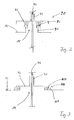
- FIGS. 2 and 3 Two embodiments of a seal 90, 100 are shown in FIGS. 2 and 3.
- the dehumidifier 50 in FIG. 1 is an adsorption dehumidifier 50.
- the adsorption dehumidifier 50 has an inlet 51 guided through the tower wall at the machine-house-side end of the tower 10 and an outlet 52 for regeneration air which can be conducted through the adsorption dehumidifier 50.
- the input 51 may optionally be provided with a filter (not shown).
- the tower wall is exposed in the machine-house-side section only low bending moments, so that the openings 51, 52 in the tower wall reduce their stability only insignificantly.
- the openings have a diameter of about 125mm.
- a wet air inlet 53, which is arranged directly on the housing of the adsorption dehumidifier 50, and a dry air outlet 54 are intended for the passage of the process air out of the tower interior through the adsorption dehumidifier 50.
- the regeneration air flow and the process air flow are substantially separated from each other in the adsorption dehumidifier 50.
- the moist air drawn into the adsorption dehumidifier 50 releases its moisture to a sorption agent applied to a sorption rotor and leaves the absorption dehumidifier 50 as dry air through the dry air outlet 54.
- Sorption, absorption and adsorption are used synonymously since the detailed functioning of the dehumidifier is not significant in the context of the application is.
- the air channel 60 At the sea bottom side end of the tower interior, the air channel 60 once again bends substantially parallel to the seabed surface and has a dry air outlet 61 at its end.
- a fan 70 is arranged next to the dehumidifier 50, which sucks the air to be dried through the adsorption dehumidifier 50 and pushes through the air channel 60 therethrough.
- an overpressure region is formed by the dry air emerging there.
- a vacuum region is created by the air sucked from the fan 70.
- the dehumidifying effect of the dehumidifier depends critically on the sealing of the tower interior. Sealing points are provided with seals. For this purpose, the particular in the sea floor side portion of the tower wall to the entry of service personnel in the tower interior door 15, designed as a double door with lock function.
- the passage 14 of the cable harness 40 is sealed with a brush seal 90.
- the edge of the passage 14 of the uppermost platform 13 has a, the implementation 14 circumferential, perpendicular projecting towards the machine house 20 strips 91 of constant width and height along the circumference, are attached to the maschinenhaus workedem end brush 92.
- a sleeve 41 is placed, which has a, arranged substantially parallel to the uppermost platform 13 plate ring 42 which in the mounted state against the brushes 92nd abuts and thus forms the actual brush seal 90.
- the brush seal 90 does not completely prevent the air exchange, but it closes in the present sense, the tower interior sealed from air exchange substantially.
- FIG. 3 shows a second embodiment of a seal 90, 100.
- the labyrinth seal 100 shown in FIG. 3 has on the machine-house-side side of the uppermost platform 13 at the edge of the feedthrough 14 three perpendicularly projecting to the machine house 20, the implementation circularly circulating strip 101. In their interstices, from a via a sleeve 41 with the harness 40 fixedly connected plate ring 42, projecting towards the seabed strip 102 a.
- the labyrinth formed by the circumferential strips 101, 102 seals in the present sense also essentially against an exchange of air.
- the spaces between the strips 101 can be filled with water so far that the protruding from the plate ring 42, engaging in the interstices strip 102 still dive into the water and an exchange of air through the labyrinth seal 100th completely prevent.
- the guided from the machine house 20 through the passage 14 harness 40 is guided in a cable loop 42 in the machine-house side section of the tower interior.
- the Jardinloop 42 allows the twisting of the cable harness during a rotation of the machine house 20 by up to three revolutions on the tower 10th
- the fan 70 is provided downstream of the adsorption dehumidifier 50 in the flow direction of the air stream circulating in the tower interior.
- the process air dried in the adsorption dehumidifier 50 is guided through the air channel 60 to the sea bottom end of the tower interior space.
- the air channel 60 is formed over its entire length parallel to the tower longitudinal direction L and has at its sea bottom end to the dry air outlet 61.
- the inlet 51 and the outlet 52 for the regeneration air are, as in the embodiment of FIG. 1, embedded in the machine-house side portion of the tower wall.
- the second embodiment of the invention according to FIG. 4 additionally has a heat exchanger 80.
- a heat exchanger 80 After the air from the fan 70 through the Moist air inlet 53 is sucked from the interior and pressed by the adsorption dehumidifier 50, it is heated by means of a downstream direction of the dehumidifier 50 arranged heat exchanger 80.
- the heat exchanger 80 has a heat medium circuit, is absorbed by the waste heat from arranged in the machine housing 20 components and is delivered to the process air in the tower interior.
- the moist process air flows through the wet air inlet 53 and the fan 70 into the adsorption dehumidifier 50, through the dehumidifier 50 and the heat exchanger 80 - in this order - from the dry air outlet 54 into the air duct 60, through it and out of the dry air outlet 61 at the sea bottom end of the tower 10 in the tower interior inside.
- the fan 70, the dehumidifier 50 and the heat exchanger 80 are connected to one another in an air-tight manner, so that the overpressure arising in the direction of the flow after the fan 70 is passed on to the drying air outlet 61 via the adsorption dehumidifier 50 and the heat exchanger 80.
- the fan 70, the dehumidifier 50 and the heat exchanger 80 are mounted on the machine house side of the upper platform 13. Due to the arrangement above the upper platform 13, said components are easily accessible for maintenance.
- Fig. 5 shows the section through the rotatably mounted on the tower 10 engine house 20.
- the interior of the machine house 20 is sealed to the outside.
- an additional dehumidifier 110 is provided in the lower, near-ground region of the interior of the machine house 20.
- the additional adsorption dehumidifier 110 is arranged in the front region of the machine housing 20 adjacent to the rotor hub 120.
- the regeneration air inlet and the regeneration air outlet of the additional adsorption dehumidifier are recessed into the machine house wall. They are about 100mm diameter slightly smaller than the regeneration air openings of Adsorptionsentfeuchters in the tower wall.
- a moist air inlet 112 at the additional adsorption dehumidifier 110 sucks in moist air of the interior of the machine house 20.
- the air line 130 is arranged below a machine carrier 121 leading to the rear part of the machine house 20 leading, and there has a dry air outlet 132 in the region between a generator 123 and a transformer 122.
- the air duct 130 is formed as a pipe with a diameter of 160 mm and optionally further along its length, further, spaced apart air outlets 131 for dry air.
- the air outlets 131 are provided in particular underneath the generator 123 and below a transmission 124 arranged upstream of it.
- the dry air in the interior of the machine house 20 remains dry longer, at least the region of the interior, in which the generator 123, the gear 124 and the transformer 122 are arranged, sealed against air exchange to the outside.
- the interior of the rotor hub 120 facing the end of two independent variants of the front seal 128, 140 in Fig. 5 are located.
- the interior of the machine house 20 is first sealed by a brush seal 140 between the machine housing lining 21 and spinner 125.
- a brush seal 141 is provided at the transition between spinner 125 and each of the three rotor blades 126.
- the interior of the spinner 125, in which the rotor hub 120 is disposed is included in the dried interior of the machine house 20.
- the brush seal 140 however, it is subject to wear due to constant rotor rotation during operation.
- a second variant of the front seal 128, 140 the interior of the spinner 125 and thus also the rotor hub 120 are not dehumidified.
- the dried interior of the machine house 20 is already sealed in the region of a bearing block 126 to the rotor hub 120 back.
- intermediate surfaces 128 are drawn in the form of tarpaulins or solid walls.
- the bearing block 126 rotatably supports a rotor shaft 127.
- This basic idea can also be used for the first variant of the interior of the hub, which is used in the interior.
- the seal to the rotor blades can be done by the blade bearings. In this case, preferably only the rotor hub 120 is dehumidified and not the entire spinner 125.
- a seal preferably in the form of a brush seal 150, at the transition between the machine house 20 and tower 10 is provided.
- the seal may be a labyrinth seal.
- the generator 123 and the transmission 124 each have a cooling device.
- the cooling devices are designed as heat exchangers and each comprise an air inlet and an air outlet.
- the air inlet is used to suck in cooler outside air, the heat of the gearbox 124 and the generator 123 receives and this gives off as warm exhaust air through the air outlet to the outside.
- the two described fresh air cooling circuits of the cooling devices are completely separated from the air of the nacelle interior.
- a gondola cooler 160 from the machine house 20 to the outside.
- the gondola cooler 160 is here designed as an air plate heat exchanger.
- the nacelle cooler 160 also has a fresh air inlet and a hot air outlet in the nacelle 20, or alternatively may be mounted outside the nacelle interior, and then has a hot air outlet and a cold air inlet for the nacelle.
- the adsorption dehumidifier 50 and the additional adsorption dehumidifier 110 are substantially identical in construction, but may differ in their performance.
Landscapes
- Engineering & Computer Science (AREA)
- Chemical & Material Sciences (AREA)
- Combustion & Propulsion (AREA)
- General Engineering & Computer Science (AREA)
- Mechanical Engineering (AREA)
- Sustainable Energy (AREA)
- Physics & Mathematics (AREA)
- Life Sciences & Earth Sciences (AREA)
- Sustainable Development (AREA)
- Thermal Sciences (AREA)
- Drying Of Gases (AREA)
- Vaporization, Distillation, Condensation, Sublimation, And Cold Traps (AREA)
- Engine Equipment That Uses Special Cycles (AREA)
- Treating Waste Gases (AREA)
- Drying Of Solid Materials (AREA)
Applications Claiming Priority (1)
| Application Number | Priority Date | Filing Date | Title |
|---|---|---|---|
| DE102005029463.4A DE102005029463B4 (de) | 2005-06-24 | 2005-06-24 | Turmentfeuchtung einer Windenergieanlage |
Publications (3)
| Publication Number | Publication Date |
|---|---|
| EP1736665A2 true EP1736665A2 (fr) | 2006-12-27 |
| EP1736665A3 EP1736665A3 (fr) | 2010-06-23 |
| EP1736665B1 EP1736665B1 (fr) | 2012-03-21 |
Family
ID=36741171
Family Applications (1)
| Application Number | Title | Priority Date | Filing Date |
|---|---|---|---|
| EP06012962A Active EP1736665B1 (fr) | 2005-06-24 | 2006-06-23 | Déshumidification de l'intérieur de la tour d'une éolienne |
Country Status (5)
| Country | Link |
|---|---|
| EP (1) | EP1736665B1 (fr) |
| AT (1) | ATE550547T1 (fr) |
| DE (1) | DE102005029463B4 (fr) |
| DK (1) | DK1736665T3 (fr) |
| ES (1) | ES2382558T3 (fr) |
Cited By (18)
| Publication number | Priority date | Publication date | Assignee | Title |
|---|---|---|---|---|
| WO2008092449A3 (fr) * | 2007-01-31 | 2009-01-08 | Vestas Wind Sys As | Convertisseur d'énergie éolienne avec déshumidificateur |
| WO2010015674A3 (fr) * | 2008-08-06 | 2010-06-03 | Frank Buss | Procédé et dispositif de gestion de l'air dans des installations d'énergie éolienne |
| WO2010051815A3 (fr) * | 2008-11-07 | 2011-01-13 | Vestas Wind Systems A/S | Dispositif et procédé d’amélioration de la déshumidification d’une centrale éolienne |
| CN102245897A (zh) * | 2008-12-17 | 2011-11-16 | 湘电达尔文有限责任公司 | 包括冷却回路的风力涡轮机 |
| WO2012000584A1 (fr) | 2010-07-01 | 2012-01-05 | Hydac Filter Systems Gmbh | Dispositif pour humidifier une substance hydraulique |
| CN102661251A (zh) * | 2012-05-10 | 2012-09-12 | 中船重工(重庆)海装风电设备有限公司 | 一种海上风力发电机的防腐冷却结构 |
| WO2012159599A1 (fr) * | 2011-05-26 | 2012-11-29 | Aerodyn Engineering Gmbh | Éolienne à circuit de refroidissement fermé |
| EP2568169A1 (fr) | 2011-09-09 | 2013-03-13 | Areva Wind GmbH | Éolienne dotée d'un système de climatisation en forme de tour utilisant de l'air extérieur |
| EP2639450A1 (fr) * | 2012-03-13 | 2013-09-18 | Alstom Wind, S.L.U. | Système de conditionnement d'air pour éolienne et procédé de ventilation et de mise en pression d'une éolienne |
| EP2669511A1 (fr) * | 2012-05-31 | 2013-12-04 | Gamesa Innovation & Technology, S.L. | Procédé et système pour empêcher la corrosion de l'équipement due à l'entrée d'air ambiant humide dans une éolienne en mer |
| WO2014072157A1 (fr) * | 2012-11-09 | 2014-05-15 | Wobben Properties Gmbh | Éolienne |
| WO2014147023A1 (fr) * | 2013-03-18 | 2014-09-25 | Cotes A/S | Procédé et agencement pour déshydrater de l'air intérieur dans des installations en mer |
| US20150198148A1 (en) * | 2009-03-13 | 2015-07-16 | Xemc Darwind B.V. | Method of constructing a wind turbine and bottom tower section of wind turbine |
| EP2960494A1 (fr) * | 2014-06-27 | 2015-12-30 | Hitachi Ltd. | Système générateur d'énergie éolienne |
| JP2016003637A (ja) * | 2014-06-19 | 2016-01-12 | 株式会社日立製作所 | 風力発電装置 |
| EP3043065A1 (fr) | 2015-01-12 | 2016-07-13 | Cotes A/S | Dispositif de dessalement pour éolienne offshore |
| EP3482815A1 (fr) * | 2017-11-08 | 2019-05-15 | Siemens Gamesa Renewable Energy A/S | Fonctionnement d'un système de refroidissement de générateur de turbine éolienne |
| WO2020127206A1 (fr) * | 2018-12-21 | 2020-06-25 | Cotes A/S | Système déshumidificateur d'éolienne comprenant une source d'énergie éolienne secondaire |
Families Citing this family (2)
| Publication number | Priority date | Publication date | Assignee | Title |
|---|---|---|---|---|
| DE102007054215A1 (de) * | 2007-11-12 | 2009-05-20 | Repower Systems Ag | Windenergieanlage mit Heizeinrichtung |
| CN102301135A (zh) * | 2009-01-30 | 2011-12-28 | 维斯塔斯风力系统集团公司 | 在顶部具有冷却器的风力涡轮机机舱 |
Family Cites Families (13)
| Publication number | Priority date | Publication date | Assignee | Title |
|---|---|---|---|---|
| JPS6449829A (en) * | 1987-08-21 | 1989-02-27 | Matsushita Electric Industrial Co Ltd | Adsorption type dehumidifying device |
| AU641083B2 (en) * | 1991-03-05 | 1993-09-09 | Matsushita Electric Industrial Co., Ltd. | Humidity control apparatus |
| DE19621485A1 (de) * | 1996-05-29 | 1998-03-12 | Schulte Franz Josef | Rotorblattheizung für Windkraftanlagen |
| WO1999030031A1 (fr) * | 1997-12-08 | 1999-06-17 | Siemens Aktiengesellschaft | Eolienne et procede de refroidissement d'un generateur d'une eolienne |
| JP2000024443A (ja) * | 1998-07-09 | 2000-01-25 | Nitto Denko Corp | 除湿装置 |
| DE19859628C1 (de) * | 1998-12-23 | 2000-03-23 | Aerodyn Eng Gmbh | Vorrichtung zur Vermeidung des Eindringens von korrosiv wirkenden Salzpartikeln |
| EP1185790B1 (fr) * | 1999-05-07 | 2004-10-27 | NEG Micon A/S | Eolienne marine a refroidissement par liquide |
| ATE250721T1 (de) * | 1999-07-14 | 2003-10-15 | Aloys Wobben | Windenergieanlage mit einem geschlossenen kühlkreislauf |
| DE19947915A1 (de) * | 1999-10-06 | 2001-04-12 | Abb Research Ltd | Kühlsystem für Baugruppen in einer Windkraftanlage |
| DE10016913A1 (de) * | 2000-04-05 | 2001-10-18 | Aerodyn Eng Gmbh | Offshore-Windenergieanlage mit einem Wärmetauschersystem |
| DE10139556A1 (de) * | 2001-08-10 | 2003-02-27 | Aloys Wobben | Einrichtung zur Entfeuchtung eines gasförmigen Mediums und Windenergieanlage mit einer solchen Einrichtung |
| DE10245103A1 (de) * | 2002-09-27 | 2004-04-08 | General Electric Co. | Schaltschrank für eine Windenergieanlage und Verfahren zum Betreiben einer Windenergieanlage |
| DE10310036A1 (de) * | 2003-02-01 | 2004-08-12 | Aloys Wobben | Verfahren zur Errichtung einer Windenergieanlage, Windenergieanlage |
-
2005
- 2005-06-24 DE DE102005029463.4A patent/DE102005029463B4/de not_active Expired - Fee Related
-
2006
- 2006-06-23 AT AT06012962T patent/ATE550547T1/de active
- 2006-06-23 DK DK06012962.4T patent/DK1736665T3/da active
- 2006-06-23 EP EP06012962A patent/EP1736665B1/fr active Active
- 2006-06-23 ES ES06012962T patent/ES2382558T3/es active Active
Cited By (40)
| Publication number | Priority date | Publication date | Assignee | Title |
|---|---|---|---|---|
| WO2008092449A3 (fr) * | 2007-01-31 | 2009-01-08 | Vestas Wind Sys As | Convertisseur d'énergie éolienne avec déshumidificateur |
| US7895847B2 (en) | 2007-01-31 | 2011-03-01 | Vestas Wind Systems A/S | Wind energy converter with dehumidifier |
| WO2010015674A3 (fr) * | 2008-08-06 | 2010-06-03 | Frank Buss | Procédé et dispositif de gestion de l'air dans des installations d'énergie éolienne |
| WO2010051815A3 (fr) * | 2008-11-07 | 2011-01-13 | Vestas Wind Systems A/S | Dispositif et procédé d’amélioration de la déshumidification d’une centrale éolienne |
| US9228566B2 (en) | 2008-12-17 | 2016-01-05 | Xemc Darwind Bv | Wind turbine comprising a cooling circuit |
| CN102245897B (zh) * | 2008-12-17 | 2014-12-03 | 湘电达尔文有限责任公司 | 包括冷却回路的风力涡轮机 |
| CN102245897A (zh) * | 2008-12-17 | 2011-11-16 | 湘电达尔文有限责任公司 | 包括冷却回路的风力涡轮机 |
| US20150198148A1 (en) * | 2009-03-13 | 2015-07-16 | Xemc Darwind B.V. | Method of constructing a wind turbine and bottom tower section of wind turbine |
| KR20130092554A (ko) | 2010-07-01 | 2013-08-20 | 하이닥 필테르 시스템즈 게엠베하 | 유압 매체로부터 습기를 제거하기 위한 디바이스 |
| CN103003580A (zh) * | 2010-07-01 | 2013-03-27 | Hydac过滤系统有限公司 | 用于对液压介质除湿的设备 |
| WO2012000584A1 (fr) | 2010-07-01 | 2012-01-05 | Hydac Filter Systems Gmbh | Dispositif pour humidifier une substance hydraulique |
| CN103003580B (zh) * | 2010-07-01 | 2016-03-23 | Hydac过滤系统有限公司 | 用于对液压介质除湿的设备 |
| US10107266B2 (en) | 2010-07-01 | 2018-10-23 | Hydac Filter Systems Gmbh | Device for removing moisture from a hydraulic medium |
| WO2012159599A1 (fr) * | 2011-05-26 | 2012-11-29 | Aerodyn Engineering Gmbh | Éolienne à circuit de refroidissement fermé |
| WO2013034627A1 (fr) | 2011-09-09 | 2013-03-14 | Areva Wind Gmbh | Éolienne avec système de climatisation du mât utilisant l'air extérieur |
| EP2568169A1 (fr) | 2011-09-09 | 2013-03-13 | Areva Wind GmbH | Éolienne dotée d'un système de climatisation en forme de tour utilisant de l'air extérieur |
| EP2568169B1 (fr) | 2011-09-09 | 2016-03-02 | Areva Wind GmbH | Éolienne dotée d'un système de climatisation en forme de tour utilisant de l'air extérieur |
| CN103782029A (zh) * | 2011-09-09 | 2014-05-07 | 阿雷瓦风力公司 | 具有使用外界空气的塔气候适应系统的风力涡轮机 |
| US10077760B2 (en) | 2011-09-09 | 2018-09-18 | Areva Wind Gmbh | Wind turbine with tower climatisation system using outside air |
| EP2639450A1 (fr) * | 2012-03-13 | 2013-09-18 | Alstom Wind, S.L.U. | Système de conditionnement d'air pour éolienne et procédé de ventilation et de mise en pression d'une éolienne |
| WO2013135743A1 (fr) * | 2012-03-13 | 2013-09-19 | Alstom Renovables España, S.L. | Systèmes de conditionnement d'air pour turbines éoliennes et procédés de ventilation et de mise sous pression de turbines éoliennes |
| CN102661251A (zh) * | 2012-05-10 | 2012-09-12 | 中船重工(重庆)海装风电设备有限公司 | 一种海上风力发电机的防腐冷却结构 |
| CN103470455A (zh) * | 2012-05-31 | 2013-12-25 | 歌美飒创新技术公司 | 防止潮湿的环境空气进入离岸风力涡轮机腐蚀设备的方法和系统 |
| EP2669511A1 (fr) * | 2012-05-31 | 2013-12-04 | Gamesa Innovation & Technology, S.L. | Procédé et système pour empêcher la corrosion de l'équipement due à l'entrée d'air ambiant humide dans une éolienne en mer |
| CN104769279A (zh) * | 2012-11-09 | 2015-07-08 | 乌本产权有限公司 | 风能设备 |
| RU2611123C2 (ru) * | 2012-11-09 | 2017-02-21 | Воббен Пропертиз Гмбх | Ветроэнергетическая установка |
| US10309375B2 (en) | 2012-11-09 | 2019-06-04 | Wobben Properties Gmbh | Wind turbine |
| AU2013343786B2 (en) * | 2012-11-09 | 2016-03-17 | Wobben Properties Gmbh | Wind turbine |
| WO2014072157A1 (fr) * | 2012-11-09 | 2014-05-15 | Wobben Properties Gmbh | Éolienne |
| CN104769279B (zh) * | 2012-11-09 | 2018-07-10 | 乌本产权有限公司 | 风能设备 |
| US9700834B2 (en) | 2013-03-18 | 2017-07-11 | Cotes A/S | Method and arrangement for dehumidifying interior air in off-shore installations |
| WO2014147023A1 (fr) * | 2013-03-18 | 2014-09-25 | Cotes A/S | Procédé et agencement pour déshydrater de l'air intérieur dans des installations en mer |
| CN105121844B (zh) * | 2013-03-18 | 2018-09-21 | 赫迪思公司 | 用于给近海设施内的内部空气除湿的方法和设置 |
| CN105121844A (zh) * | 2013-03-18 | 2015-12-02 | 赫迪思公司 | 用于给近海设施内的内部空气除湿的方法和设置 |
| JP2016003637A (ja) * | 2014-06-19 | 2016-01-12 | 株式会社日立製作所 | 風力発電装置 |
| EP2960494A1 (fr) * | 2014-06-27 | 2015-12-30 | Hitachi Ltd. | Système générateur d'énergie éolienne |
| EP3043065A1 (fr) | 2015-01-12 | 2016-07-13 | Cotes A/S | Dispositif de dessalement pour éolienne offshore |
| EP3482815A1 (fr) * | 2017-11-08 | 2019-05-15 | Siemens Gamesa Renewable Energy A/S | Fonctionnement d'un système de refroidissement de générateur de turbine éolienne |
| US11146143B2 (en) | 2017-11-08 | 2021-10-12 | Siemens Gamesa Renewable Energy A/S | Operating a wind turbine generator cooling system |
| WO2020127206A1 (fr) * | 2018-12-21 | 2020-06-25 | Cotes A/S | Système déshumidificateur d'éolienne comprenant une source d'énergie éolienne secondaire |
Also Published As
| Publication number | Publication date |
|---|---|
| EP1736665A3 (fr) | 2010-06-23 |
| ATE550547T1 (de) | 2012-04-15 |
| DE102005029463B4 (de) | 2015-10-29 |
| DE102005029463A1 (de) | 2006-12-28 |
| EP1736665B1 (fr) | 2012-03-21 |
| ES2382558T3 (es) | 2012-06-11 |
| DK1736665T3 (da) | 2012-07-02 |
Similar Documents
| Publication | Publication Date | Title |
|---|---|---|
| EP1736665B1 (fr) | Déshumidification de l'intérieur de la tour d'une éolienne | |
| DE102004064007B4 (de) | Windenergieanlage mit einer Generatorkühlung | |
| WO2010015674A2 (fr) | Procédé et dispositif de gestion de l'air dans des installations d'énergie éolienne | |
| EP1419350A1 (fr) | Installation d'energie eolienne | |
| DE2430475A1 (de) | Verfahren und kuehlturm zum abfuehren von abwaerme | |
| DE10245103A1 (de) | Schaltschrank für eine Windenergieanlage und Verfahren zum Betreiben einer Windenergieanlage | |
| DE2703114A1 (de) | Anlage zur klimatisierung von orten mit heissem klima und zur suesswassergewinnung an diesen orten | |
| EP3048296A1 (fr) | Procede de degivrage d'une pale de rotor d'une eolienne | |
| WO2018202247A1 (fr) | Dispositif pour produire de l'eau à partir d'une atmosphère ambiante | |
| EP2000668A1 (fr) | Eolienne dotée de refroidissement passif | |
| EP2531776A1 (fr) | Procédé et dispositif pour la déshumidification de l'air ambiant dans le domaine off-shore | |
| EP2418431B1 (fr) | Dispositif de climatisation doté d'un dispositif de conditionnement de l'air | |
| CH652276A5 (de) | Verfahren und anlage zum trocknen eines feuchten gutes, insbesondere von landwirtschaftlichen produkten. | |
| DE102012108992A1 (de) | Verfahren und Vorrichtung zum Betrieb eines luftgekühlten Kondensationsapparates | |
| EP2875290B1 (fr) | Dispositif d'alimentation en air frais et procédé d'alimentation en air frais d'une installation en mer | |
| EP2546595A1 (fr) | Dispositif et procédé de refroidissement | |
| EP2727642A1 (fr) | Appareil de déshumidification pour fluide gazeux | |
| EP2795127B1 (fr) | Boîtier d'un appareil avec des moyens pour refroidir de l'air entrant ledit boîtier | |
| DE102012000129B4 (de) | Verfahren und Vorrichtung zum Gewinnen von Trinkwasser | |
| DE102009017053A1 (de) | Wärmetauschervorrichtung | |
| WO2012159599A1 (fr) | Éolienne à circuit de refroidissement fermé | |
| DE102009006198B4 (de) | Vorrichtung zur großtechnischen Medienkonditionierung | |
| DE102017110698B4 (de) | Windkraftwerk und Verfahren zum Betreiben eines Windkraftwerks | |
| EP1250949A1 (fr) | Procédé et installation pour récuperer la chaleur latente et sensible dans les fumées de combustion | |
| DE202007013488U1 (de) | Ein Klimagerät mit einem einzelnen Zentrifugalwindrad |
Legal Events
| Date | Code | Title | Description |
|---|---|---|---|
| PUAI | Public reference made under article 153(3) epc to a published international application that has entered the european phase |
Free format text: ORIGINAL CODE: 0009012 |
|
| AK | Designated contracting states |
Kind code of ref document: A2 Designated state(s): AT BE BG CH CY CZ DE DK EE ES FI FR GB GR HU IE IS IT LI LT LU LV MC NL PL PT RO SE SI SK TR |
|
| AX | Request for extension of the european patent |
Extension state: AL BA HR MK YU |
|
| PUAL | Search report despatched |
Free format text: ORIGINAL CODE: 0009013 |
|
| AK | Designated contracting states |
Kind code of ref document: A3 Designated state(s): AT BE BG CH CY CZ DE DK EE ES FI FR GB GR HU IE IS IT LI LT LU LV MC NL PL PT RO SE SI SK TR |
|
| AX | Request for extension of the european patent |
Extension state: AL BA HR MK RS |
|
| RIC1 | Information provided on ipc code assigned before grant |
Ipc: F03D 11/00 20060101AFI20100520BHEP |
|
| 17P | Request for examination filed |
Effective date: 20101209 |
|
| AKX | Designation fees paid |
Designated state(s): AT BE BG CH CY CZ DE DK EE ES FI FR GB GR HU IE IS IT LI LT LU LV MC NL PL PT RO SE SI SK TR |
|
| REG | Reference to a national code |
Ref country code: DE Ref legal event code: R079 Ref document number: 502006011147 Country of ref document: DE Free format text: PREVIOUS MAIN CLASS: F03D0011040000 Ipc: F03D0011000000 |
|
| GRAC | Information related to communication of intention to grant a patent modified |
Free format text: ORIGINAL CODE: EPIDOSCIGR1 |
|
| GRAP | Despatch of communication of intention to grant a patent |
Free format text: ORIGINAL CODE: EPIDOSNIGR1 |
|
| RIC1 | Information provided on ipc code assigned before grant |
Ipc: F03D 11/00 20060101AFI20110907BHEP |
|
| GRAS | Grant fee paid |
Free format text: ORIGINAL CODE: EPIDOSNIGR3 |
|
| GRAA | (expected) grant |
Free format text: ORIGINAL CODE: 0009210 |
|
| AK | Designated contracting states |
Kind code of ref document: B1 Designated state(s): AT BE BG CH CY CZ DE DK EE ES FI FR GB GR HU IE IS IT LI LT LU LV MC NL PL PT RO SE SI SK TR |
|
| RAP1 | Party data changed (applicant data changed or rights of an application transferred) |
Owner name: REPOWER SYSTEMS SE |
|
| REG | Reference to a national code |
Ref country code: GB Ref legal event code: FG4D Free format text: NOT ENGLISH |
|
| REG | Reference to a national code |
Ref country code: CH Ref legal event code: EP |
|
| REG | Reference to a national code |
Ref country code: IE Ref legal event code: FG4D Free format text: LANGUAGE OF EP DOCUMENT: GERMAN |
|
| REG | Reference to a national code |
Ref country code: AT Ref legal event code: REF Ref document number: 550547 Country of ref document: AT Kind code of ref document: T Effective date: 20120415 |
|
| REG | Reference to a national code |
Ref country code: DE Ref legal event code: R096 Ref document number: 502006011147 Country of ref document: DE Effective date: 20120516 |
|
| REG | Reference to a national code |
Ref country code: ES Ref legal event code: FG2A Ref document number: 2382558 Country of ref document: ES Kind code of ref document: T3 Effective date: 20120611 |
|
| REG | Reference to a national code |
Ref country code: DK Ref legal event code: T3 |
|
| REG | Reference to a national code |
Ref country code: NL Ref legal event code: VDEP Effective date: 20120321 |
|
| PG25 | Lapsed in a contracting state [announced via postgrant information from national office to epo] |
Ref country code: LT Free format text: LAPSE BECAUSE OF FAILURE TO SUBMIT A TRANSLATION OF THE DESCRIPTION OR TO PAY THE FEE WITHIN THE PRESCRIBED TIME-LIMIT Effective date: 20120321 |
|
| LTIE | Lt: invalidation of european patent or patent extension |
Effective date: 20120321 |
|
| PG25 | Lapsed in a contracting state [announced via postgrant information from national office to epo] |
Ref country code: FI Free format text: LAPSE BECAUSE OF FAILURE TO SUBMIT A TRANSLATION OF THE DESCRIPTION OR TO PAY THE FEE WITHIN THE PRESCRIBED TIME-LIMIT Effective date: 20120321 Ref country code: GR Free format text: LAPSE BECAUSE OF FAILURE TO SUBMIT A TRANSLATION OF THE DESCRIPTION OR TO PAY THE FEE WITHIN THE PRESCRIBED TIME-LIMIT Effective date: 20120622 Ref country code: LV Free format text: LAPSE BECAUSE OF FAILURE TO SUBMIT A TRANSLATION OF THE DESCRIPTION OR TO PAY THE FEE WITHIN THE PRESCRIBED TIME-LIMIT Effective date: 20120321 |
|
| PG25 | Lapsed in a contracting state [announced via postgrant information from national office to epo] |
Ref country code: CY Free format text: LAPSE BECAUSE OF FAILURE TO SUBMIT A TRANSLATION OF THE DESCRIPTION OR TO PAY THE FEE WITHIN THE PRESCRIBED TIME-LIMIT Effective date: 20120321 |
|
| PG25 | Lapsed in a contracting state [announced via postgrant information from national office to epo] |
Ref country code: RO Free format text: LAPSE BECAUSE OF FAILURE TO SUBMIT A TRANSLATION OF THE DESCRIPTION OR TO PAY THE FEE WITHIN THE PRESCRIBED TIME-LIMIT Effective date: 20120321 Ref country code: PL Free format text: LAPSE BECAUSE OF FAILURE TO SUBMIT A TRANSLATION OF THE DESCRIPTION OR TO PAY THE FEE WITHIN THE PRESCRIBED TIME-LIMIT Effective date: 20120321 Ref country code: CZ Free format text: LAPSE BECAUSE OF FAILURE TO SUBMIT A TRANSLATION OF THE DESCRIPTION OR TO PAY THE FEE WITHIN THE PRESCRIBED TIME-LIMIT Effective date: 20120321 Ref country code: SE Free format text: LAPSE BECAUSE OF FAILURE TO SUBMIT A TRANSLATION OF THE DESCRIPTION OR TO PAY THE FEE WITHIN THE PRESCRIBED TIME-LIMIT Effective date: 20120321 Ref country code: IS Free format text: LAPSE BECAUSE OF FAILURE TO SUBMIT A TRANSLATION OF THE DESCRIPTION OR TO PAY THE FEE WITHIN THE PRESCRIBED TIME-LIMIT Effective date: 20120721 Ref country code: SI Free format text: LAPSE BECAUSE OF FAILURE TO SUBMIT A TRANSLATION OF THE DESCRIPTION OR TO PAY THE FEE WITHIN THE PRESCRIBED TIME-LIMIT Effective date: 20120321 Ref country code: EE Free format text: LAPSE BECAUSE OF FAILURE TO SUBMIT A TRANSLATION OF THE DESCRIPTION OR TO PAY THE FEE WITHIN THE PRESCRIBED TIME-LIMIT Effective date: 20120321 |
|
| PG25 | Lapsed in a contracting state [announced via postgrant information from national office to epo] |
Ref country code: PT Free format text: LAPSE BECAUSE OF FAILURE TO SUBMIT A TRANSLATION OF THE DESCRIPTION OR TO PAY THE FEE WITHIN THE PRESCRIBED TIME-LIMIT Effective date: 20120723 Ref country code: SK Free format text: LAPSE BECAUSE OF FAILURE TO SUBMIT A TRANSLATION OF THE DESCRIPTION OR TO PAY THE FEE WITHIN THE PRESCRIBED TIME-LIMIT Effective date: 20120321 |
|
| BERE | Be: lapsed |
Owner name: REPOWER SYSTEMS SE Effective date: 20120630 |
|
| PLBE | No opposition filed within time limit |
Free format text: ORIGINAL CODE: 0009261 |
|
| STAA | Information on the status of an ep patent application or granted ep patent |
Free format text: STATUS: NO OPPOSITION FILED WITHIN TIME LIMIT |
|
| PG25 | Lapsed in a contracting state [announced via postgrant information from national office to epo] |
Ref country code: NL Free format text: LAPSE BECAUSE OF FAILURE TO SUBMIT A TRANSLATION OF THE DESCRIPTION OR TO PAY THE FEE WITHIN THE PRESCRIBED TIME-LIMIT Effective date: 20120321 Ref country code: MC Free format text: LAPSE BECAUSE OF NON-PAYMENT OF DUE FEES Effective date: 20120630 |
|
| REG | Reference to a national code |
Ref country code: CH Ref legal event code: PL |
|
| REG | Reference to a national code |
Ref country code: CH Ref legal event code: PL |
|
| 26N | No opposition filed |
Effective date: 20130102 |
|
| PG25 | Lapsed in a contracting state [announced via postgrant information from national office to epo] |
Ref country code: IT Free format text: LAPSE BECAUSE OF FAILURE TO SUBMIT A TRANSLATION OF THE DESCRIPTION OR TO PAY THE FEE WITHIN THE PRESCRIBED TIME-LIMIT Effective date: 20120321 |
|
| REG | Reference to a national code |
Ref country code: IE Ref legal event code: MM4A |
|
| REG | Reference to a national code |
Ref country code: DE Ref legal event code: R097 Ref document number: 502006011147 Country of ref document: DE Effective date: 20130102 |
|
| PG25 | Lapsed in a contracting state [announced via postgrant information from national office to epo] |
Ref country code: BE Free format text: LAPSE BECAUSE OF NON-PAYMENT OF DUE FEES Effective date: 20120630 Ref country code: CH Free format text: LAPSE BECAUSE OF NON-PAYMENT OF DUE FEES Effective date: 20120630 Ref country code: IE Free format text: LAPSE BECAUSE OF NON-PAYMENT OF DUE FEES Effective date: 20120623 Ref country code: LI Free format text: LAPSE BECAUSE OF NON-PAYMENT OF DUE FEES Effective date: 20120630 |
|
| PG25 | Lapsed in a contracting state [announced via postgrant information from national office to epo] |
Ref country code: BG Free format text: LAPSE BECAUSE OF FAILURE TO SUBMIT A TRANSLATION OF THE DESCRIPTION OR TO PAY THE FEE WITHIN THE PRESCRIBED TIME-LIMIT Effective date: 20120621 |
|
| REG | Reference to a national code |
Ref country code: AT Ref legal event code: MM01 Ref document number: 550547 Country of ref document: AT Kind code of ref document: T Effective date: 20120623 |
|
| PG25 | Lapsed in a contracting state [announced via postgrant information from national office to epo] |
Ref country code: AT Free format text: LAPSE BECAUSE OF NON-PAYMENT OF DUE FEES Effective date: 20120623 |
|
| PG25 | Lapsed in a contracting state [announced via postgrant information from national office to epo] |
Ref country code: TR Free format text: LAPSE BECAUSE OF FAILURE TO SUBMIT A TRANSLATION OF THE DESCRIPTION OR TO PAY THE FEE WITHIN THE PRESCRIBED TIME-LIMIT Effective date: 20120321 |
|
| PG25 | Lapsed in a contracting state [announced via postgrant information from national office to epo] |
Ref country code: LU Free format text: LAPSE BECAUSE OF NON-PAYMENT OF DUE FEES Effective date: 20120623 |
|
| PG25 | Lapsed in a contracting state [announced via postgrant information from national office to epo] |
Ref country code: HU Free format text: LAPSE BECAUSE OF FAILURE TO SUBMIT A TRANSLATION OF THE DESCRIPTION OR TO PAY THE FEE WITHIN THE PRESCRIBED TIME-LIMIT Effective date: 20060623 |
|
| REG | Reference to a national code |
Ref country code: ES Ref legal event code: PC2A Owner name: SENVION SE Effective date: 20150127 |
|
| REG | Reference to a national code |
Ref country code: DE Ref legal event code: R082 Ref document number: 502006011147 Country of ref document: DE Representative=s name: GROTH PATENTANWAELTE, DE |
|
| REG | Reference to a national code |
Ref country code: DE Ref legal event code: R081 Ref document number: 502006011147 Country of ref document: DE Owner name: SENVION SE, DE Free format text: FORMER OWNER: REPOWER SYSTEMS AG, 22297 HAMBURG, DE Effective date: 20120327 Ref country code: DE Ref legal event code: R081 Ref document number: 502006011147 Country of ref document: DE Owner name: SENVION SE, DE Free format text: FORMER OWNER: REPOWER SYSTEMS SE, 22297 HAMBURG, DE Effective date: 20150227 Ref country code: DE Ref legal event code: R082 Ref document number: 502006011147 Country of ref document: DE Representative=s name: GROTH PATENTANWAELTE, DE Effective date: 20150227 Ref country code: DE Ref legal event code: R081 Ref document number: 502006011147 Country of ref document: DE Owner name: SENVION GMBH, DE Free format text: FORMER OWNER: REPOWER SYSTEMS AG, 22297 HAMBURG, DE Effective date: 20120327 Ref country code: DE Ref legal event code: R081 Ref document number: 502006011147 Country of ref document: DE Owner name: SENVION GMBH, DE Free format text: FORMER OWNER: REPOWER SYSTEMS SE, 22297 HAMBURG, DE Effective date: 20150227 |
|
| REG | Reference to a national code |
Ref country code: FR Ref legal event code: CD Owner name: SENVION SE, DE Effective date: 20150330 |
|
| REG | Reference to a national code |
Ref country code: DE Ref legal event code: R082 Ref document number: 502006011147 Country of ref document: DE Representative=s name: GROTH PATENTANWAELTE, DE Ref country code: DE Ref legal event code: R081 Ref document number: 502006011147 Country of ref document: DE Owner name: SENVION GMBH, DE Free format text: FORMER OWNER: SENVION SE, 22297 HAMBURG, DE |
|
| REG | Reference to a national code |
Ref country code: FR Ref legal event code: PLFP Year of fee payment: 11 |
|
| REG | Reference to a national code |
Ref country code: FR Ref legal event code: PLFP Year of fee payment: 12 |
|
| REG | Reference to a national code |
Ref country code: FR Ref legal event code: PLFP Year of fee payment: 13 |
|
| PGFP | Annual fee paid to national office [announced via postgrant information from national office to epo] |
Ref country code: ES Payment date: 20200717 Year of fee payment: 15 |
|
| REG | Reference to a national code |
Ref country code: DE Ref legal event code: R081 Ref document number: 502006011147 Country of ref document: DE Owner name: SIEMENS GAMESA RENEWABLE ENERGY SERVICE GMBH, DE Free format text: FORMER OWNER: SENVION GMBH, 22297 HAMBURG, DE |
|
| REG | Reference to a national code |
Ref country code: ES Ref legal event code: FD2A Effective date: 20220830 |
|
| PG25 | Lapsed in a contracting state [announced via postgrant information from national office to epo] |
Ref country code: ES Free format text: LAPSE BECAUSE OF NON-PAYMENT OF DUE FEES Effective date: 20210624 |
|
| REG | Reference to a national code |
Ref country code: GB Ref legal event code: 732E Free format text: REGISTERED BETWEEN 20230727 AND 20230802 |
|
| PGFP | Annual fee paid to national office [announced via postgrant information from national office to epo] |
Ref country code: DE Payment date: 20250626 Year of fee payment: 20 |
|
| PGFP | Annual fee paid to national office [announced via postgrant information from national office to epo] |
Ref country code: GB Payment date: 20250617 Year of fee payment: 20 Ref country code: DK Payment date: 20250619 Year of fee payment: 20 |
|
| PGFP | Annual fee paid to national office [announced via postgrant information from national office to epo] |
Ref country code: FR Payment date: 20250624 Year of fee payment: 20 |
|
| REG | Reference to a national code |
Ref country code: DE Ref legal event code: R082 Ref document number: 502006011147 Country of ref document: DE Representative=s name: GROTH, LL.M., WIELAND, DIPL.-PHYS. DIPL.-MATH., DE |