EP1736675A1 - Dispositif a déplacement linéaire avec étiquette d'identification par radio-fréquence - Google Patents
Dispositif a déplacement linéaire avec étiquette d'identification par radio-fréquence Download PDFInfo
- Publication number
- EP1736675A1 EP1736675A1 EP20050013555 EP05013555A EP1736675A1 EP 1736675 A1 EP1736675 A1 EP 1736675A1 EP 20050013555 EP20050013555 EP 20050013555 EP 05013555 A EP05013555 A EP 05013555A EP 1736675 A1 EP1736675 A1 EP 1736675A1
- Authority
- EP
- European Patent Office
- Prior art keywords
- linear motion
- rfid tag
- motion device
- guide member
- support body
- Prior art date
- Legal status (The legal status is an assumption and is not a legal conclusion. Google has not performed a legal analysis and makes no representation as to the accuracy of the status listed.)
- Granted
Links
- 238000005096 rolling process Methods 0.000 claims description 12
- 238000000034 method Methods 0.000 claims description 8
- 238000007639 printing Methods 0.000 claims description 7
- 238000004364 calculation method Methods 0.000 claims description 6
- 239000004033 plastic Substances 0.000 claims description 4
- 238000005538 encapsulation Methods 0.000 claims description 3
- 239000004065 semiconductor Substances 0.000 claims description 3
- 238000005304 joining Methods 0.000 description 4
- 229910052710 silicon Inorganic materials 0.000 description 4
- 239000010703 silicon Substances 0.000 description 4
- XUIMIQQOPSSXEZ-UHFFFAOYSA-N Silicon Chemical compound [Si] XUIMIQQOPSSXEZ-UHFFFAOYSA-N 0.000 description 3
- 239000013078 crystal Substances 0.000 description 3
- 238000004519 manufacturing process Methods 0.000 description 3
- 229910000831 Steel Inorganic materials 0.000 description 2
- 230000006378 damage Effects 0.000 description 2
- 230000000694 effects Effects 0.000 description 2
- 239000010959 steel Substances 0.000 description 2
- 238000004026 adhesive bonding Methods 0.000 description 1
- 238000005452 bending Methods 0.000 description 1
- 230000000295 complement effect Effects 0.000 description 1
- 239000002826 coolant Substances 0.000 description 1
- 238000001514 detection method Methods 0.000 description 1
- 238000006073 displacement reaction Methods 0.000 description 1
- 238000004146 energy storage Methods 0.000 description 1
- 230000007613 environmental effect Effects 0.000 description 1
- 239000011888 foil Substances 0.000 description 1
- 230000006870 function Effects 0.000 description 1
- 238000002347 injection Methods 0.000 description 1
- 239000007924 injection Substances 0.000 description 1
- 238000001746 injection moulding Methods 0.000 description 1
- 238000009434 installation Methods 0.000 description 1
- 239000000463 material Substances 0.000 description 1
- 230000003534 oscillatory effect Effects 0.000 description 1
- 239000002985 plastic film Substances 0.000 description 1
- 229920006255 plastic film Polymers 0.000 description 1
- 150000003376 silicon Chemical class 0.000 description 1
- 238000003860 storage Methods 0.000 description 1
- 230000000007 visual effect Effects 0.000 description 1
Images

Classifications
-
- F—MECHANICAL ENGINEERING; LIGHTING; HEATING; WEAPONS; BLASTING
- F16—ENGINEERING ELEMENTS AND UNITS; GENERAL MEASURES FOR PRODUCING AND MAINTAINING EFFECTIVE FUNCTIONING OF MACHINES OR INSTALLATIONS; THERMAL INSULATION IN GENERAL
- F16C—SHAFTS; FLEXIBLE SHAFTS; ELEMENTS OR CRANKSHAFT MECHANISMS; ROTARY BODIES OTHER THAN GEARING ELEMENTS; BEARINGS
- F16C29/00—Bearings for parts moving only linearly
-
- F—MECHANICAL ENGINEERING; LIGHTING; HEATING; WEAPONS; BLASTING
- F16—ENGINEERING ELEMENTS AND UNITS; GENERAL MEASURES FOR PRODUCING AND MAINTAINING EFFECTIVE FUNCTIONING OF MACHINES OR INSTALLATIONS; THERMAL INSULATION IN GENERAL
- F16C—SHAFTS; FLEXIBLE SHAFTS; ELEMENTS OR CRANKSHAFT MECHANISMS; ROTARY BODIES OTHER THAN GEARING ELEMENTS; BEARINGS
- F16C29/00—Bearings for parts moving only linearly
- F16C29/04—Ball or roller bearings
- F16C29/06—Ball or roller bearings in which the rolling bodies circulate partly without carrying load
- F16C29/0602—Details of the bearing body or carriage or parts thereof, e.g. methods for manufacturing or assembly
- F16C29/0609—Details of the bearing body or carriage or parts thereof, e.g. methods for manufacturing or assembly of the ends of the bearing body or carriage where the rolling elements change direction, e.g. end caps
-
- F—MECHANICAL ENGINEERING; LIGHTING; HEATING; WEAPONS; BLASTING
- F16—ENGINEERING ELEMENTS AND UNITS; GENERAL MEASURES FOR PRODUCING AND MAINTAINING EFFECTIVE FUNCTIONING OF MACHINES OR INSTALLATIONS; THERMAL INSULATION IN GENERAL
- F16C—SHAFTS; FLEXIBLE SHAFTS; ELEMENTS OR CRANKSHAFT MECHANISMS; ROTARY BODIES OTHER THAN GEARING ELEMENTS; BEARINGS
- F16C41/00—Other accessories, e.g. devices integrated in the bearing not relating to the bearing function as such
- F16C41/008—Identification means, e.g. markings, RFID-tags; Data transfer means
-
- F—MECHANICAL ENGINEERING; LIGHTING; HEATING; WEAPONS; BLASTING
- F16—ENGINEERING ELEMENTS AND UNITS; GENERAL MEASURES FOR PRODUCING AND MAINTAINING EFFECTIVE FUNCTIONING OF MACHINES OR INSTALLATIONS; THERMAL INSULATION IN GENERAL
- F16C—SHAFTS; FLEXIBLE SHAFTS; ELEMENTS OR CRANKSHAFT MECHANISMS; ROTARY BODIES OTHER THAN GEARING ELEMENTS; BEARINGS
- F16C29/00—Bearings for parts moving only linearly
- F16C29/04—Ball or roller bearings
- F16C29/06—Ball or roller bearings in which the rolling bodies circulate partly without carrying load
- F16C29/0633—Ball or roller bearings in which the rolling bodies circulate partly without carrying load with a bearing body defining a U-shaped carriage, i.e. surrounding a guide rail or track on three sides
- F16C29/0635—Ball or roller bearings in which the rolling bodies circulate partly without carrying load with a bearing body defining a U-shaped carriage, i.e. surrounding a guide rail or track on three sides whereby the return paths are provided as bores in a main body of the U-shaped carriage, e.g. the main body of the U-shaped carriage is a single part with end caps provided at each end
- F16C29/0638—Ball or roller bearings in which the rolling bodies circulate partly without carrying load with a bearing body defining a U-shaped carriage, i.e. surrounding a guide rail or track on three sides whereby the return paths are provided as bores in a main body of the U-shaped carriage, e.g. the main body of the U-shaped carriage is a single part with end caps provided at each end with balls
- F16C29/0642—Ball or roller bearings in which the rolling bodies circulate partly without carrying load with a bearing body defining a U-shaped carriage, i.e. surrounding a guide rail or track on three sides whereby the return paths are provided as bores in a main body of the U-shaped carriage, e.g. the main body of the U-shaped carriage is a single part with end caps provided at each end with balls with four rows of balls
- F16C29/0645—Ball or roller bearings in which the rolling bodies circulate partly without carrying load with a bearing body defining a U-shaped carriage, i.e. surrounding a guide rail or track on three sides whereby the return paths are provided as bores in a main body of the U-shaped carriage, e.g. the main body of the U-shaped carriage is a single part with end caps provided at each end with balls with four rows of balls with load directions in O-arrangement
Definitions
- the invention relates to a linear motion device according to the preamble of claim 1.
- linear motion devices are in particular Wälz Eisengewindetriebe and linear bearings such as ball bushings, ball and roller rail guides and ball splines.
- Linear motion devices of this kind are known from the prior art and are widely used, for example, in machine tools. Usually, these devices are provided with labels such as type, serial number, accuracy class and date of manufacture. More recently, there has been a demand to make such labels computer readable, e.g. can be detected automatically during storage. Barcodes are already being used today for this purpose.
- RFID tags r adio f requency i dentification
- Such tags can be read without contact by means of electromagnetic waves. They usually require no energy storage, as they are also supplied with readout by means of electromagnetic waves from the outside with energy.
- These tags have the advantage over bar codes that they can store more data and that they can be read over longer distances and without visual contact.
- a data processing unit is provided in an RFID tag, for example, the saved data with encryption methods against unauthorized reading.
- RFID tags are used according to the EP 1 339 014 A1 or the EP 0 155 662 A2 attached to tools so that the machine control can take into account the actual tool dimensions stored therein in the control of the tool path.
- the corresponding tags are offered for example by the company Balluff under the name "Information System BIS C" on the market and are characterized by a high degree of protection of IP67 according to IEC 60529, ie the tags themselves are against the special stresses in a machine tool particularly well protected by coolants, chips, etc. and therefore relatively expensive.
- the object of the invention to protect an RFID tag on a linear motion device and, at the same time, install it inexpensively without impairing the function of the RFID tag.
- This object is achieved in that the electrically non-conductive guide member is provided with an RFID tag, the RFID tag is not accessible from the outside.
- An RFID tag would thus not work if it were placed in a cavity of the support body because the steel would shield the electromagnetic waves during readout. In an arrangement on the surface of the support body, the tag would not be protected or would have to be laboriously protected with separate covers.
- the rolling element guide members provide an ideal location for housing an RFID tag.
- the guide parts which are formed in a linear roller bearing, for example, by the end caps or a ball screw, for example, from the deflectors are usually injection molded from plastic and thus electrically non-conductive. The electromagnetic waves during reading can thus penetrate the guide part unhindered and reach the RFID tag. At the same time it is possible in the plastic injection molding with minimal additional costs to provide a corresponding receiving space for the RFID tag in the guide part. It should be noted that the RFID tag is very small. There are thus also small guide components such as deflectors and slim guide rails for installation in question.
- the RFID tag can be arranged between the guide component and the carrier body.
- a cavity for the RFID tag in the guide member in the form of a recess can thus be closed without additional effort by the support body, whereby the tag is protected against environmental influences.
- the RFID tag recess it is necessary for the RFID tag recess to be arranged on a side of the guide component facing the carrier body. The shielding effect of the support body with respect to the electromagnetic waves when reading the tag can be accepted, since this Nevertheless, waves propagate into the shaded area due to diffraction and reflection effects.
- the guide components for the rolling elements can certainly be constructed in several parts, as for example from the EP 0 971 140 A1 is known.
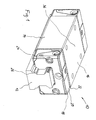
- the corresponding linear motion device in the form of a ball rail guide is shown in the attached Figures 1 and 2.
- the linear motion device 10 consists of a rod 12 and a rotor 14.
- the rotor 14 consists of a support body 16 and guide members 18 for the rolling elements, not shown, namely a top plate 20 and a baffle 22.
- the top plate 20 and the baffle 22 are inserted into each other and fastened together with screws 24 on the support body 16.
- the rolling elements are based on the support body 16 and on the rod 12 load-transmitting, so that the rotor along the rod 12 is guided linearly movable.
- raceways 26 are provided, which are complementary to the raceways, not shown, carried out on the support body 16.
- deflection channels 28 are provided, which are bounded by the baffle 22 inwards.
- the deflection channels 28 are part of an endless circulation channel in which the rolling elements rotate.
- the RFID tag is arranged according to the invention in the already existing cavity 30 of the top plate 20 and is thus between the at least one guide member 18, namely the top plate 20, and the support body 16 and is not accessible from the outside.
- the cavity 30 is closed only indirectly by the support body 16, since the baffle 22 is disposed between the support body 16 and the top plate 20.
- the guide component consists of plastic, wherein the RFID tag is cast into the guide component.
- This embodiment is useful when the RFID tag is also for protection against Product counterfeiting should be used, as is known in principle.
- counterfeit products are a problem since they are offered in different accuracy classes that are not different from the outside but have a significantly different price. It is therefore important that the information about the accuracy class of a linear motion device is immutable and inseparable from it. This goal can be achieved with the described embodiment, because the tag can then be removed only by destroying the guide components. In addition, the finding of the tag by a counterfeiter is made considerably more difficult.
- the RFID tag according to the invention is cast in a corner region 32 of the top plate 20.
- This embodiment Due to the low price of an RFID tag, it makes sense to label all guide parts with an RFID tag, which further complicates product counterfeiting.
- This embodiment also has the advantage that it can automatically check after assembly of the linear motion device, whether the correct components were assembled. This is particularly useful if the guide components are manufactured in different tolerance classes, which can be easily confused. For control purposes, the linear motion device only needs to be brought into the detection area of a corresponding RFID tag reader. Subsequently, a computer connected to the reader can automatically query the various components provided according to a manufacturing bill of materials and check for completeness and correct selection.
- the RFID tag can consist of an electronic circuit and an antenna, the antenna being applied directly to the guide component by a printing process.
- an RFID tag for example, according to the US Pat. No. 6,424,263 B1 is constructed, can be dispensed with the carrier film.
- the antenna can be easily applied to any joining surface of the guide member without providing a separate receiving recess, since it requires almost no space in the thickness direction.
- the antenna according to the invention is printed on the joining surface 34, since this is particularly well accessible for printing.
- the antenna is sealed at this point by the baffle 22 made of rubber to the environment particularly well. If the electronic circuit is designed as a silicon chip, a matched recess is provided for this in the baffle 22.
- the electronic circuit of the RFID tag consists of organic semiconductors and is applied directly to the guide component by a printing process.
- the antenna and the electronic circuit can thus be applied simultaneously to the guide member.
- An expensive wiring between the antenna and a conventional electronic circuit in the form of a silicon chip can be omitted.
- the electronic circuit according to the invention is printed on the joining surface 34 adjacent to the antenna.
- the RFID tag may comprise a memory and a data processing unit, wherein load information from the outside wirelessly into the memory are transferable and wherein the data processing unit from the stress information calculate the expected remaining life of the linear motion device and wirelessly transmitted to the outside.
- load information from the outside wirelessly into the memory are transferable and wherein the data processing unit from the stress information calculate the expected remaining life of the linear motion device and wirelessly transmitted to the outside.
- the higher-level machine therefore only has to transmit the necessary load information wirelessly to the RFID tags and can then also wirelessly query the remaining service life or the state of wear. In this case, only one RFID tag transmitting / receiving device is necessary for all linear motion devices in a parent machine.
- the necessary load information is available anyway in the control of the higher-level machine.
- these are, for example, the drive torque and the number of spindle revolutions.
- the drive torque can be derived, for example, from the drive current of the electric motor that drives the spindle, wherein the drive current is usually controlled by the control of the parent machine and is thus known.
- the number of Spindle revolutions can in turn be determined with the aid of the position measuring systems connected to the control of the higher-level machine.
- the life calculation can be carried out on the basis of this data, for example, according to the information in the catalog "Rexroth ball screws" (R310DE 3301, Issue 2004.11, pages 118 to 121) of the applicant from the data processing unit of the RFID tag.
- the reliability of the determined residual life value can be improved by providing in the linear motion device a sensor which detects vibrations of the rotor, wherein the vibration information is taken into account in the calculation of the remaining service life. From the vibrations of the rotor, in particular those of the support body, a statement about the imminent failure of the linear motion device can be made, as the failure often go damage to the WälzSystemonnebahnen advance. When rolling the rolling elements on the damaged raceways in turn increased vibrations in the support body arise.
- a vibration sensor is in a ball rail guide according to FIGS. 1 and 2, for example, a piezoelectric crystal into consideration. Certain piezocrystals, which are also used in loudspeakers, for example, release an electrical voltage when they are bent.
- the central web 36 of the support body 16 is the portion of the support body which is subjected to the greatest bending.
- the electrical voltage which the piezoelectric crystal emits during the operation of the linear motion device is thus a measure of the oscillatory movements of the carrier body and can be correspondingly evaluated by the RFID tag in order to determine the expected remaining service life of the linear motion device in conjunction with the above-described calculation.
- the RFID tag is permanently supplied with energy, for example by means of a battery, with it the occurring vibrations can be evaluated at any time and not only during the interrogation of the RFID tag.
- the linear motion device may be a rolling element screw, wherein in the RFID tag, the actual relationship between rotational position and travel of WälzSystemgewindetriebs is stored and this relationship is taken into account by the control of a parent machine in the attitude control of the rotor. From the DE 16 38 032 C3 or the US 5,237,509 It is known to take into account the inaccuracy of a screw drive of a machine in the position control by means of a correction table. Thus, instead of a linear displacement measuring system, a less expensive rotary encoder can be used without the positioning accuracy of the machine suffers.
- the correction table which assigns the actual travel path of the rotor to each rotational position of the threaded spindle of the rolling element, is hereby stored in the machine control.
Landscapes
- Engineering & Computer Science (AREA)
- General Engineering & Computer Science (AREA)
- Mechanical Engineering (AREA)
- General Factory Administration (AREA)
- Bearings For Parts Moving Linearly (AREA)
Priority Applications (3)
| Application Number | Priority Date | Filing Date | Title |
|---|---|---|---|
| EP20050013555 EP1736675B1 (fr) | 2005-06-23 | 2005-06-23 | Dispositif a déplacement linéaire avec étiquette d'identification par radio-fréquence |
| DE200550003332 DE502005003332D1 (de) | 2005-06-23 | 2005-06-23 | Linearbewegungsvorrichtung mit RFID-Tag |
| US11/455,414 US7479885B2 (en) | 2005-06-23 | 2006-06-19 | Linear motion device with an RFID tag |
Applications Claiming Priority (1)
| Application Number | Priority Date | Filing Date | Title |
|---|---|---|---|
| EP20050013555 EP1736675B1 (fr) | 2005-06-23 | 2005-06-23 | Dispositif a déplacement linéaire avec étiquette d'identification par radio-fréquence |
Publications (2)
| Publication Number | Publication Date |
|---|---|
| EP1736675A1 true EP1736675A1 (fr) | 2006-12-27 |
| EP1736675B1 EP1736675B1 (fr) | 2008-03-19 |
Family
ID=35355078
Family Applications (1)
| Application Number | Title | Priority Date | Filing Date |
|---|---|---|---|
| EP20050013555 Expired - Lifetime EP1736675B1 (fr) | 2005-06-23 | 2005-06-23 | Dispositif a déplacement linéaire avec étiquette d'identification par radio-fréquence |
Country Status (3)
| Country | Link |
|---|---|
| US (1) | US7479885B2 (fr) |
| EP (1) | EP1736675B1 (fr) |
| DE (1) | DE502005003332D1 (fr) |
Cited By (5)
| Publication number | Priority date | Publication date | Assignee | Title |
|---|---|---|---|---|
| DE102007009093A1 (de) | 2007-02-24 | 2008-08-28 | Schaeffler Kg | Wälzlager mit RFID-Tag |
| DE102008013088A1 (de) | 2008-03-07 | 2009-09-10 | Robert Bosch Gmbh | Verfahren zur Inbetriebnahme einer Linearbewegungseinheit |
| DE102008036225A1 (de) | 2008-08-02 | 2010-02-04 | Schaeffler Kg | Lagerbestandteil und Lageranordnung mit einer Antenne |
| CN103846682A (zh) * | 2013-03-11 | 2014-06-11 | 南京理工大学 | 一种侧向预紧式滚滑复合导轨结构 |
| WO2018233750A1 (fr) * | 2017-06-21 | 2018-12-27 | Schaeffler Technologies AG & Co. KG | Procédé pour la lubrification d'un guidage linéaire et guidage linéaire |
Families Citing this family (11)
| Publication number | Priority date | Publication date | Assignee | Title |
|---|---|---|---|---|
| US8316742B2 (en) * | 2007-12-11 | 2012-11-27 | Kennametal Inc. | Cutting tool with integrated circuit chip |
| DE102008006819B4 (de) * | 2008-01-31 | 2020-01-23 | Robert Bosch Gmbh | Führungswagen mit hoher Breite |
| WO2009117396A2 (fr) * | 2008-03-17 | 2009-09-24 | Suprock Christopher A | Système d’usinage intelligent et porte-outil intelligent correspondant |
| JP5756302B2 (ja) * | 2011-02-09 | 2015-07-29 | 日本トムソン株式会社 | 潤滑機能を備えた極小形の直動案内ユニット |
| JP5912426B2 (ja) | 2011-11-07 | 2016-04-27 | ヤマハ発動機株式会社 | リニアコンベア |
| US9169868B2 (en) * | 2012-05-01 | 2015-10-27 | Chieftech Precision Co., Ltd. | Movable member for linear slide assembly |
| US9019081B2 (en) | 2013-02-19 | 2015-04-28 | Tyco Fire & Security Gmbh | Tag detacher with haptic feedback |
| DE102013220321A1 (de) | 2013-10-09 | 2015-04-09 | Robert Bosch Gmbh | Hydrauliksystem mit einem für eine Steuerung auslesbaren Datenspeicher |
| WO2015058793A1 (fr) * | 2013-10-23 | 2015-04-30 | Aktiebolaget Skf | Procédé de production d'un produit support avec un code d'authentification |
| US9611107B2 (en) | 2014-12-08 | 2017-04-04 | Rockwell Automation Technologies, Inc. | Linear drive transport system and method |
| US10492747B2 (en) | 2016-07-18 | 2019-12-03 | KUB Technologies, Inc. | System and method for extending and retracting a moveable arm |
Citations (7)
| Publication number | Priority date | Publication date | Assignee | Title |
|---|---|---|---|---|
| EP0971140A1 (fr) * | 1998-07-06 | 2000-01-12 | Deutsche Star GmbH | Dispositif de guidage linéaire muni d'un système de lubrification |
| US20020186134A1 (en) * | 2001-06-11 | 2002-12-12 | The Timken Company | Bearing with data storage device |
| WO2004072747A1 (fr) * | 2003-02-14 | 2004-08-26 | Ntn Corporation | Composant de machine utilisant une etiquette a puce et son procede de controle de la qualite et systeme de detection d'anomalie |
| JP2005042895A (ja) * | 2003-07-25 | 2005-02-17 | Nsk Ltd | 転がり軸受装置 |
| JP2005140606A (ja) * | 2003-11-06 | 2005-06-02 | Nsk Ltd | 転がり軸受ユニットの荷重測定装置及びその製造装置 |
| WO2005052398A1 (fr) * | 2003-11-25 | 2005-06-09 | Ntn Corporation | Palier avec etiquette a circuit integre et joint d'etancheite pour ce palier |
| WO2005052397A1 (fr) * | 2003-11-25 | 2005-06-09 | Ntn Corporation | Palier avec etiquette a circuit integre et joint d'etancheite pour ce palier |
Family Cites Families (18)
| Publication number | Priority date | Publication date | Assignee | Title |
|---|---|---|---|---|
| DE1339014U (fr) | ||||
| US3555254A (en) * | 1967-04-17 | 1971-01-12 | Gerber Scientific Instr Co | Error correcting system and method for use with plotters, machine tools and the like |
| FR2230238A5 (fr) * | 1973-05-16 | 1974-12-13 | Tech Integrale | |
| DE3407716A1 (de) | 1984-03-02 | 1985-09-12 | Robert Bosch Gmbh, 7000 Stuttgart | Einrichtung zum messen der staerke von verschleissteilen |
| DE3410410A1 (de) | 1984-03-21 | 1985-09-26 | Maho Werkzeugmaschinenbau Babel & Co, 8962 Pfronten | Werkzeughalter mit datentraeger zur kennung seines werkzeuges |
| JPH03260708A (ja) * | 1990-03-09 | 1991-11-20 | Toshiba Mach Co Ltd | 位置誤差補正方法 |
| JP2001516110A (ja) * | 1997-09-11 | 2001-09-25 | プレシジョン ダイナミクス コーポレイション | 可撓性の基体による高周波同定識別用タグ |
| DE69938929D1 (de) * | 1998-09-11 | 2008-07-31 | Motorola Inc | Rfid-etikettenvorrichtung und verfahren |
| US6986418B2 (en) * | 1998-12-10 | 2006-01-17 | Martin Engineering Company | Conveyor belt cleaner scraper blade with sensor and control system therefor |
| US6441741B1 (en) * | 1999-05-17 | 2002-08-27 | Avid Identification Systems, Inc. | Overmolded transponder |
| US6939044B1 (en) * | 1999-10-22 | 2005-09-06 | Thomson Industries, Inc. | Recirculating rolling element cartridge for linear motion bearing assembly |
| JP4568453B2 (ja) * | 2000-05-29 | 2010-10-27 | Thk株式会社 | 運動案内装置 |
| US6424263B1 (en) * | 2000-12-01 | 2002-07-23 | Microchip Technology Incorporated | Radio frequency identification tag on a single layer substrate |
| DE10126439A1 (de) * | 2001-05-31 | 2002-12-05 | Ina Schaeffler Kg | Linearwälzlagerelement |
| DE50213109D1 (de) * | 2001-10-04 | 2009-01-22 | Continental Teves Ag & Co Ohg | System zur übertragung von reifenzustandsgrössen |
| JP2003161319A (ja) * | 2001-11-27 | 2003-06-06 | Ndc Co Ltd | 直線案内滑り軸受 |
| US7116213B2 (en) * | 2002-11-22 | 2006-10-03 | Michelin Recherche Et Technique S.A. | Acoustic wave device with modulation functionality |
| US7005987B2 (en) * | 2003-10-30 | 2006-02-28 | Michelin Recherche Et Technique S.A. | Acoustic wave device with digital data transmission functionality |
-
2005
- 2005-06-23 DE DE200550003332 patent/DE502005003332D1/de not_active Expired - Lifetime
- 2005-06-23 EP EP20050013555 patent/EP1736675B1/fr not_active Expired - Lifetime
-
2006
- 2006-06-19 US US11/455,414 patent/US7479885B2/en not_active Expired - Fee Related
Patent Citations (7)
| Publication number | Priority date | Publication date | Assignee | Title |
|---|---|---|---|---|
| EP0971140A1 (fr) * | 1998-07-06 | 2000-01-12 | Deutsche Star GmbH | Dispositif de guidage linéaire muni d'un système de lubrification |
| US20020186134A1 (en) * | 2001-06-11 | 2002-12-12 | The Timken Company | Bearing with data storage device |
| WO2004072747A1 (fr) * | 2003-02-14 | 2004-08-26 | Ntn Corporation | Composant de machine utilisant une etiquette a puce et son procede de controle de la qualite et systeme de detection d'anomalie |
| JP2005042895A (ja) * | 2003-07-25 | 2005-02-17 | Nsk Ltd | 転がり軸受装置 |
| JP2005140606A (ja) * | 2003-11-06 | 2005-06-02 | Nsk Ltd | 転がり軸受ユニットの荷重測定装置及びその製造装置 |
| WO2005052398A1 (fr) * | 2003-11-25 | 2005-06-09 | Ntn Corporation | Palier avec etiquette a circuit integre et joint d'etancheite pour ce palier |
| WO2005052397A1 (fr) * | 2003-11-25 | 2005-06-09 | Ntn Corporation | Palier avec etiquette a circuit integre et joint d'etancheite pour ce palier |
Non-Patent Citations (1)
| Title |
|---|
| PATENT ABSTRACTS OF JAPAN vol. 2003, no. 12 5 December 2003 (2003-12-05) * |
Cited By (5)
| Publication number | Priority date | Publication date | Assignee | Title |
|---|---|---|---|---|
| DE102007009093A1 (de) | 2007-02-24 | 2008-08-28 | Schaeffler Kg | Wälzlager mit RFID-Tag |
| DE102008013088A1 (de) | 2008-03-07 | 2009-09-10 | Robert Bosch Gmbh | Verfahren zur Inbetriebnahme einer Linearbewegungseinheit |
| DE102008036225A1 (de) | 2008-08-02 | 2010-02-04 | Schaeffler Kg | Lagerbestandteil und Lageranordnung mit einer Antenne |
| CN103846682A (zh) * | 2013-03-11 | 2014-06-11 | 南京理工大学 | 一种侧向预紧式滚滑复合导轨结构 |
| WO2018233750A1 (fr) * | 2017-06-21 | 2018-12-27 | Schaeffler Technologies AG & Co. KG | Procédé pour la lubrification d'un guidage linéaire et guidage linéaire |
Also Published As
| Publication number | Publication date |
|---|---|
| DE502005003332D1 (de) | 2008-04-30 |
| EP1736675B1 (fr) | 2008-03-19 |
| US20060290507A1 (en) | 2006-12-28 |
| US7479885B2 (en) | 2009-01-20 |
Similar Documents
| Publication | Publication Date | Title |
|---|---|---|
| EP1736675B1 (fr) | Dispositif a déplacement linéaire avec étiquette d'identification par radio-fréquence | |
| EP0976103B1 (fr) | Carte de donnees, procede de production d'une carte de donnees et dispositif permettant de produire une telle carte de donnees | |
| EP1959240B1 (fr) | Encodeur et son procédé de fonctionnement | |
| EP2995424B1 (fr) | Pince | |
| EP1053447B1 (fr) | Dispositif de surveillance continue de la jonction d'une bande transporteuse | |
| EP2533018B1 (fr) | Système de mesure de trajectoire linéaire | |
| EP3126810A1 (fr) | Entraînement par courroie et procédé permettant de surveiller ledit entraînement | |
| WO2005023688A1 (fr) | Dispositif de controle d'une installation de convoyage | |
| EP3377436A1 (fr) | Procédé de détermination d'informations relatives à des composants d'ascenseur reçus logés dans une cage d'ascenseur | |
| DE102011011300A1 (de) | Rollenantrieb und Verfahren zum Steuern einer Anlage | |
| DE112004002235T5 (de) | Lager mit IC-Kennzeichnung und Dichtung dafür | |
| WO2000030240A9 (fr) | Moteur lineaire et partie secondaire pour moteur lineaire | |
| DE102018215783A1 (de) | Positionserfassungssystem und Verfahren zur Erfassung einer Bewegung einer Maschine | |
| DE102008013088A1 (de) | Verfahren zur Inbetriebnahme einer Linearbewegungseinheit | |
| DE102006015065A1 (de) | Einbaumotor, insbesondere Einbau-Torquemotor | |
| DE102007020940B3 (de) | Vorrichtung zum Erkennen und Überwachen von Schäden bei Wälzlagern | |
| DE202014011110U1 (de) | Handzange | |
| DE10314795A1 (de) | Messeinrichtung zur berührungslosen Messung von Positionen, Wegen und/oder Winkeln sowie daraus ableitbaren Größen | |
| DE202012005284U1 (de) | Lineares Wegmesssystem | |
| EP2897263B1 (fr) | Moteur électrique avec capteur de position rotative | |
| DE19955685A1 (de) | Identifikationselement | |
| DE102008048164A1 (de) | Antriebseinheit, umfassend rotativen Direktantrieb und kapazitives Absolutmesssystem | |
| DE102019108981B4 (de) | Radsatzlager für ein Schienenfahrzeug und Verfahren zum Betrieb einer Sensorik eines Radsatzlagers | |
| DE102015212728A1 (de) | Elektronischer Betriebsdatenspeicher für eine rotatorisch arbeitende Maschine | |
| AT410036B (de) | Codierbare chipkarte |
Legal Events
| Date | Code | Title | Description |
|---|---|---|---|
| PUAI | Public reference made under article 153(3) epc to a published international application that has entered the european phase |
Free format text: ORIGINAL CODE: 0009012 |
|
| 17P | Request for examination filed |
Effective date: 20051220 |
|
| AK | Designated contracting states |
Kind code of ref document: A1 Designated state(s): AT BE BG CH CY CZ DE DK EE ES FI FR GB GR HU IE IS IT LI LT LU MC NL PL PT RO SE SI SK TR |
|
| AX | Request for extension of the european patent |
Extension state: AL BA HR LV MK YU |
|
| GRAP | Despatch of communication of intention to grant a patent |
Free format text: ORIGINAL CODE: EPIDOSNIGR1 |
|
| GRAS | Grant fee paid |
Free format text: ORIGINAL CODE: EPIDOSNIGR3 |
|
| AKX | Designation fees paid |
Designated state(s): CH DE FR IT LI |
|
| GRAA | (expected) grant |
Free format text: ORIGINAL CODE: 0009210 |
|
| AK | Designated contracting states |
Kind code of ref document: B1 Designated state(s): CH DE FR IT LI |
|
| REG | Reference to a national code |
Ref country code: CH Ref legal event code: NV Representative=s name: A. BRAUN, BRAUN, HERITIER, ESCHMANN AG PATENTANWAE Ref country code: CH Ref legal event code: EP |
|
| REF | Corresponds to: |
Ref document number: 502005003332 Country of ref document: DE Date of ref document: 20080430 Kind code of ref document: P |
|
| REG | Reference to a national code |
Ref country code: CH Ref legal event code: PFA Owner name: BOSCH REXROTH MECHATRONICS GMBH Free format text: BOSCH REXROTH MECHATRONICS GMBH#ERNST-SACHS-STRASSE 100#97424 SCHWEINFURT (DE) -TRANSFER TO- BOSCH REXROTH MECHATRONICS GMBH#ERNST-SACHS-STRASSE 100#97424 SCHWEINFURT (DE) |
|
| ET | Fr: translation filed | ||
| PLBE | No opposition filed within time limit |
Free format text: ORIGINAL CODE: 0009261 |
|
| STAA | Information on the status of an ep patent application or granted ep patent |
Free format text: STATUS: NO OPPOSITION FILED WITHIN TIME LIMIT |
|
| 26N | No opposition filed |
Effective date: 20081222 |
|
| REG | Reference to a national code |
Ref country code: DE Ref legal event code: R081 Ref document number: 502005003332 Country of ref document: DE Owner name: ROBERT BOSCH GMBH, DE Free format text: FORMER OWNER: BOSCH REXROTH MECHATRONICS GMBH, 97424 SCHWEINFURT, DE Effective date: 20120725 |
|
| PGFP | Annual fee paid to national office [announced via postgrant information from national office to epo] |
Ref country code: CH Payment date: 20130621 Year of fee payment: 9 |
|
| PGFP | Annual fee paid to national office [announced via postgrant information from national office to epo] |
Ref country code: FR Payment date: 20130703 Year of fee payment: 9 |
|
| PGFP | Annual fee paid to national office [announced via postgrant information from national office to epo] |
Ref country code: DE Payment date: 20130828 Year of fee payment: 9 |
|
| PGFP | Annual fee paid to national office [announced via postgrant information from national office to epo] |
Ref country code: IT Payment date: 20130621 Year of fee payment: 9 |
|
| REG | Reference to a national code |
Ref country code: CH Ref legal event code: PCAR Free format text: NEW ADDRESS: HOLBEINSTRASSE 36-38, 4051 BASEL (CH) |
|
| REG | Reference to a national code |
Ref country code: DE Ref legal event code: R119 Ref document number: 502005003332 Country of ref document: DE |
|
| REG | Reference to a national code |
Ref country code: CH Ref legal event code: PL |
|
| REG | Reference to a national code |
Ref country code: FR Ref legal event code: ST Effective date: 20150227 |
|
| REG | Reference to a national code |
Ref country code: DE Ref legal event code: R119 Ref document number: 502005003332 Country of ref document: DE Effective date: 20150101 |
|
| PG25 | Lapsed in a contracting state [announced via postgrant information from national office to epo] |
Ref country code: LI Free format text: LAPSE BECAUSE OF NON-PAYMENT OF DUE FEES Effective date: 20140630 Ref country code: CH Free format text: LAPSE BECAUSE OF NON-PAYMENT OF DUE FEES Effective date: 20140630 Ref country code: DE Free format text: LAPSE BECAUSE OF NON-PAYMENT OF DUE FEES Effective date: 20150101 Ref country code: IT Free format text: LAPSE BECAUSE OF NON-PAYMENT OF DUE FEES Effective date: 20140623 |
|
| PG25 | Lapsed in a contracting state [announced via postgrant information from national office to epo] |
Ref country code: FR Free format text: LAPSE BECAUSE OF NON-PAYMENT OF DUE FEES Effective date: 20140630 |