EP1736708A1 - Befestigungsvorrichtung für einen Heizkörper - Google Patents
Befestigungsvorrichtung für einen Heizkörper Download PDFInfo
- Publication number
- EP1736708A1 EP1736708A1 EP06009513A EP06009513A EP1736708A1 EP 1736708 A1 EP1736708 A1 EP 1736708A1 EP 06009513 A EP06009513 A EP 06009513A EP 06009513 A EP06009513 A EP 06009513A EP 1736708 A1 EP1736708 A1 EP 1736708A1
- Authority
- EP
- European Patent Office
- Prior art keywords
- rail
- locking element
- retainer device
- radiator
- retainer
- Prior art date
- Legal status (The legal status is an assumption and is not a legal conclusion. Google has not performed a legal analysis and makes no representation as to the accuracy of the status listed.)
- Withdrawn
Links
- 239000000758 substrate Substances 0.000 claims abstract description 12
- 238000004519 manufacturing process Methods 0.000 claims description 4
- 238000010276 construction Methods 0.000 description 4
- 239000000463 material Substances 0.000 description 4
- 230000014509 gene expression Effects 0.000 description 2
- 230000009471 action Effects 0.000 description 1
- 230000015572 biosynthetic process Effects 0.000 description 1
- 239000002131 composite material Substances 0.000 description 1
- 238000005516 engineering process Methods 0.000 description 1
- 229910000078 germane Inorganic materials 0.000 description 1
- 238000000034 method Methods 0.000 description 1
- 230000008569 process Effects 0.000 description 1
- 230000008439 repair process Effects 0.000 description 1
Images



Classifications
-
- F—MECHANICAL ENGINEERING; LIGHTING; HEATING; WEAPONS; BLASTING
- F24—HEATING; RANGES; VENTILATING
- F24D—DOMESTIC- OR SPACE-HEATING SYSTEMS, e.g. CENTRAL HEATING SYSTEMS; DOMESTIC HOT-WATER SUPPLY SYSTEMS; ELEMENTS OR COMPONENTS THEREFOR
- F24D19/00—Details
- F24D19/02—Arrangement of mountings or supports for radiators
- F24D19/024—Functioning details of supporting means for radiators
- F24D19/0273—Radiators fixed in order to prevent undesired detachment
-
- F—MECHANICAL ENGINEERING; LIGHTING; HEATING; WEAPONS; BLASTING
- F24—HEATING; RANGES; VENTILATING
- F24D—DOMESTIC- OR SPACE-HEATING SYSTEMS, e.g. CENTRAL HEATING SYSTEMS; DOMESTIC HOT-WATER SUPPLY SYSTEMS; ELEMENTS OR COMPONENTS THEREFOR
- F24D19/00—Details
- F24D19/02—Arrangement of mountings or supports for radiators
-
- F—MECHANICAL ENGINEERING; LIGHTING; HEATING; WEAPONS; BLASTING
- F24—HEATING; RANGES; VENTILATING
- F24D—DOMESTIC- OR SPACE-HEATING SYSTEMS, e.g. CENTRAL HEATING SYSTEMS; DOMESTIC HOT-WATER SUPPLY SYSTEMS; ELEMENTS OR COMPONENTS THEREFOR
- F24D19/00—Details
- F24D19/02—Arrangement of mountings or supports for radiators
- F24D19/0203—Types of supporting means
- F24D19/0216—Supporting means having a rail
-
- F—MECHANICAL ENGINEERING; LIGHTING; HEATING; WEAPONS; BLASTING
- F24—HEATING; RANGES; VENTILATING
- F24D—DOMESTIC- OR SPACE-HEATING SYSTEMS, e.g. CENTRAL HEATING SYSTEMS; DOMESTIC HOT-WATER SUPPLY SYSTEMS; ELEMENTS OR COMPONENTS THEREFOR
- F24D19/00—Details
- F24D19/02—Arrangement of mountings or supports for radiators
- F24D19/024—Functioning details of supporting means for radiators
- F24D19/0273—Radiators fixed in order to prevent undesired detachment
- F24D19/0283—Radiators fixed on the top
-
- F—MECHANICAL ENGINEERING; LIGHTING; HEATING; WEAPONS; BLASTING
- F24—HEATING; RANGES; VENTILATING
- F24D—DOMESTIC- OR SPACE-HEATING SYSTEMS, e.g. CENTRAL HEATING SYSTEMS; DOMESTIC HOT-WATER SUPPLY SYSTEMS; ELEMENTS OR COMPONENTS THEREFOR
- F24D19/00—Details
- F24D19/02—Arrangement of mountings or supports for radiators
- F24D19/024—Functioning details of supporting means for radiators
- F24D19/0273—Radiators fixed in order to prevent undesired detachment
- F24D19/0286—Radiators fixed using a spring
-
- F—MECHANICAL ENGINEERING; LIGHTING; HEATING; WEAPONS; BLASTING
- F24—HEATING; RANGES; VENTILATING
- F24D—DOMESTIC- OR SPACE-HEATING SYSTEMS, e.g. CENTRAL HEATING SYSTEMS; DOMESTIC HOT-WATER SUPPLY SYSTEMS; ELEMENTS OR COMPONENTS THEREFOR
- F24D2220/00—Components of central heating installations excluding heat sources
- F24D2220/20—Heat consumers
- F24D2220/2009—Radiators
- F24D2220/2054—Panel radiators with or without extended convection surfaces
Definitions
- the present invention relates to a device for mounting a radiator on a substrate, comprising an elongate rail formed for fixing on the substrate; a first retainer device at a first end region of the rail and formed for cooperation with a first portion of the radiator or an engagement device disposed thereon; a second retainer d4evice at an opposing second end region of the rail and formed for cooperation with a second portion of the radiator or an engagement device disposed thereon, the second retainer device being movable along the rail towards and away from the first retainer device; and a locking element disposed in the second retainer device For preventing unintentional lifting of the radiator from the mounting device.
- a very large number of different mounting devices are previously known in the art for retaining a radiator against a substrate, typically a wall.
- Many such mounting devices include, as has been intimated by way of introduction, an elongate rail which is mounted on a substrate and two retainer devices that engage with some part of, or on the radiator.
- a mounting device which comprises a first fixed retainer device and a helical spring that draws a second movable retainer device in a direction towards the first retainer device.
- the spring is disposed to extend between the rail and the movable retainer device so that it not only draws the retainer device but also a locking element in a direction towards the first retainer device.
- the purpose of the locking element is to prevent the second retainer device fro moving away from the first against the action of the helical spring, so that the radiator unintentionally loosens from the mounting device, for example on being jolted. On intentional dismounting of the radiator, use is made of a special tool for releasing the locking element.
- the object of the present invention is to realise a mounting device which functions well in that unintentional loosening is actually prevented, at the same time as the use of the mounting device is intended to be as simple as possible.
- a mounting device contain as few components as possible, for facilitating manufacture, assembly and storage.
- the object forming the basis of the present invention will be attained if the device intimated by way of introduction is characterised in that the locking element makes an angle ⁇ with the rail and is urged against the rail with a force striving to rotate the locking element so that the angle ⁇ increases.
- Fig. 1 shows a mounting device 1 according to the invention together with a radiator 2 which the mounting device 1 is intended to mount on a substrate, usually a wall.
- the mounting device 1 largely includes a rail 3 disposed on the substrate, upper and lower retainer devices, of which only the upper retainer device 4 is shown in Fig. 1, and spring means 8 which acts on the locking element 5.
- the radiator 2 is gripped by the upper retainer device 4 around its upper edge 6 via an adapter 7. While this is not shown in the Figures, it is also conceivable that the retainer device 4 be formed for directly gripping around the edge 6 of the radiator 2 or also with an engagement device specifically provided for this purpose, for example on that side of the radiator 2 turned to face towards the wall.
- the radiator 2 is preferably gripped by an additional retainer device included in the mounting device 1 which, however, is not shown in the Figures.
- This retainer device is typically fixed and, in the preferred embodiment which is shown in Fig. 1, it would grasp around the lower edge of the radiator 2 or a lower engagement device on the radiator 2.
- the design of the lower, typically fixed retainer device may vary and is not a germane part of the invention unless it is designed as the retainer device in Fig. 1.
- the rail 3 is secured in the substrate by means of screws or similar fixing means. Both the fixing means and the rail 3 are of relatively conventional type and will be described in greater detail hereinbelow with reference to Fig. 5. However, it should be pointed out that the rail 3 is quite elongate so that it extends between the two retainer devices of which the movable retainer device 4 is shown. Finally, the rail 3 is also provided with one or more holes for receiving the fixing means.
- the retainer device 4 which is movable is shown in Fig. 1 and grips directly around some portion of the radiator 2, or via an adapter 7 in the manner illustrated in Fig. 1 or in any corresponding manner.
- the locking element 5 makes an angle ⁇ with the rail 3.
- the outer edge of the locking element 5 which is not shown in Fig. 1 is in contact with the rail 3.
- the contact between the locking element 5 and the rail 3 is so strong that a powerful engagement between them is obtained and prevents the retainer device 4 from moving upwards, which entails that unintentional loosening of the radiator 2 from the mounting device 1 is counteracted.
- An upward movement of the retainer device 4 while the locking element 5 is in engagement with the rail 3 would namely entail that the angle ⁇ would increase.
- This is strongly counteracted by the inherent material properties of the locking element 5 and the spring means 8.
- a downward movement of the retainer device 4, which would lead to an improved engagement with the radiator 2, is however not prevented by the locking element 5.
- Such a movement tends to reduce the angle ⁇ , which entails that its contact forces with the rail 3 are reduced, whereby the friction between the locking element 5 and the rail 3 is reduced so that the movement is permitted.
- the spring means 8 is connected to the locking element 5 at that end which is opposite to the rail 3.
- the spring means 8 and the locking element 5 are resilient in relation to one another and when they are urged towards one another, they elastically strive away from one another. This results in the engagement of the locking element 5 with the rail 3 becoming stronger and improved if the spring means 8 is constantly urged against the locking element 5, i.e. if the spring means 8 is pretensioned towards the locking element 5.
- the material properties in the locking element 5 and the spring means 8, as well as the elasticity therein are such that it is simpler to press the locking, element 5 and the spring means 8 to one another in relation to an unloaded position than to separate them from one another from the unloaded position.
- This factor results in the device according to the present invention having, in the preferred embodiment, a so-called one way locking with the aid of the locking element 5.
- a one way locking entails that a movement in one direction, i.e. downwards in Fig. 1, of the movable retainer device 4 is permitted, while an upward movement, or away from the fixed retainer device, is not possible.
- an upward movement thereof requires that the locking element 5 be actuated with the aid if a special tool.
- a special tool grasps directly in the locking element 5 and reduces the angle ⁇ between the locking element 5 and the rail 3. In such instance, the locking element 5 loses, or at least reduces its contact with the rail 3 and an upward movement of the retainer device 4 is made possible.
- the spring means 8 and the locking element 5 are of one piece manufacture with one another, even though it is possible to conceive of an embodiment where the spring means 8 is manufactured separately from the locking element 5.
- the spring means 8 need not even be a leaf spring, as shown in Fig. 1, but could very well be any other type of spring which pretensions the locking element in such a manner that the angle ⁇ strives to increase.
- Fig. 2a shows the retainer device in detail without the rail 3 and the combined locking element 5 and spring means 8.
- the retainer device 4 is provided with an engagement member 9 for engagement either directly with the radiator 2 or with an adapter 7.
- the retainer device 4 is provided with a pair of upper projections 10, of which only the one is visible in the side elevation according to Fig. 2a.
- the function of the upper projection 10 is to serve as a support on manual downward actuation of the retainer device 4 to a fixed engagement with the radiator 2 on mounting thereof.
- the recesses 11 are disposed to receive a part of the spring means 8, which will be described in greater detail below.
- the entry of the recess 11 is relatively wide so that a part of the spring means 8 can be inserted therein, while the recess 11 has an upwardly angled section 13 which is considerably narrower than the width of the entry 12, but which is nevertheless sufficiently large to receive a section of the spring means 8, i.e. the angled section 13 is wider than the thickness of the spring means 8.
- a fixing device 14 which is realised in that a portion of the material in the retainer device 4 is bent inwards.
- the presence of the fixing device 14 contributes in retaining the spring means 8 in a pretensioned position, and thereby the locking element 5, already before the retainer device 4 has been mounted on the rail 3.
- the retainer device 4 has two lateral projections 15 which are provided for guiding in and maintaining the retainer device 4 in a slidable position at the end area of the rail 3.
- the function of the lateral projections 15 will be clarified further in the description of the detailed formation of the rail 3 given below, with reference to Fig. 5.
- Fig. 2b shows the composite locking element and spring means 5, 8. Together, this arrangement has an angled form with two shanks 16 and 17, the long shank 16 constituting the main portion of the spring means 8, while the short shank 17 constitutes the main portion of the locking element 5.
- a pair of projections or fixing lugs 18 symmetrically thereon.
- the fixing lugs 18 are disposed to be inserted in the recesses 11 in the retainer device 4.
- catch means 19 On the short shank 17, there are disposed a pair of catch means 19, preferably on both sides thereof The catch means 19 are disposed for engagement with the fixing device 14 at least temporarily, but possibly also permanently.
- a tongue 20 At the end of the short shank 17, there is disposed a tongue 20.
- the function of the tongue 20 is to guide the locking element 5 in the rail 3.
- a groove 24 is provided in the rail 3. This groove 24 is shown first in Fig. 5a, which will be described in greater detail below.
- Fig. 3a is a plan view of the combined spring means and locking element 8 and 5, seen in the direction of the arrow A in Fig. 2b. It is more clearly apparent from this view that both the fixing lugs 18 and the catch means 19 in the preferred embodiment are disposed in mirror symmetry around an imaginary plane through the locking element and spring means 5 and 8. The tongue 20 is also more clearly visible in this view.
- Fig. 3b shows the combined locking element and spring means 5 and 8 in perspective, which may serve the purpose of further clarifying the mutual positioning of the fixing lugs 18, the catch means 19 and the tongue 20 as well as their respective orientations.
- Fig. 4a is a plan view of the retainer device 4 with the mounted spring means 8.
- the positioning of the locking element 5 can only be guessed in this Figure.
- the view which is shown in Fig. 4a is that side which is turned to face towards the radiator 2 on use of the mounting device 1.
- the fixing lugs 18 are inserted in recesses 11 in the retainer device 4 and are securely held in position in that they are moved into the angled section 13 and thereby cannot simply be released, since the spring means 8 is slightly pretensioned. This pretensioning is realised in that the catch means 19 now engage around the fixing devices 14.
- Fig. 4s shows the retainer device 4 with the locking element 5 and the spring means 8 mounted therein. This view is taken in the opposite direction compared with the view in Fig. 4a, i.e. that side of the retainer device 4 which is turned to face towards the rail 3 disposed on the substrate, i.e. the wall, is shown.
- the locking element 5 with the tongue 20 are particularly clearly apparent from this view.
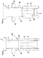
- Fig. 5a is a plan view of an en portion 21 of the rail 3.
- Fig. 5b shows the same end portion in end elevation, i.e. seen from the arrow B in Fig. 5a.
- an inward fold 22 is made on each side of the material in the rail 3.
- a guide 23 is formed in which the lateral projections 15 on the retainer device 4 may be accommodated. Further guiding of the locking element 5, apart from the inward guiding which the retainer device 4 provides will be obtained by the groove 24 in which the tongue 20 of the locking element 5 is intended to run. On both sides of the groove 24, the free edge of the locking element 5 will abut and engage powerfully.
- Fig. 5a also shows a hole 25 which is intended for securing of the rail 3 in the substrate, in general a wall.
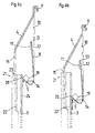
- Fig. 6a shows the upper retainer device 4 in the process of being mounted on the rail 3.
- the radiator 2 is not included in this Figure, even though, in normal cases, it is disposed in the proximity of the rail 3, typically supported on the retainer device disposed in the opposite end of the rail 3.
- the retainer device 4 has been passed down a distance in the guide 23 and the tongue 20 has snapped into the groove 24. Since the locking element 5 extends on both sides of the groove 24, its edge will abut against the rail 3 in these regions, and prevents the tongue 20 from projecting further into the groove 24.
- That position which is shown in Fig. 6a is the uppermost position in which the retainer device 4 can be deemed to be mounted on the rail 3.
- the locking element 5 is in contact with the rail 3 and prevents in principle an upward movement of the retainer device 4.
- the tongue 20 will also provide an additional locking against the retainer device 4 being drawn upwards. The reason for this is that the tongue 20 will come into contact with the upper region of the groove 24 I this position.
- the contact of the locking element 5 with the rail 3 is, however, sufficient to prevent an unintentional upward movement of the retainer device 4.
- Fig. 6b shows a more typical position of use when the radiator 2 has been mounted in place with the aid of the mounting device 1.
- the contact between the locking element 5 and the rail 3 prevents, as was mentioned above, an upward movement.
- a release of the radiator 2 is desired, for example on replacement or repair, it is possible to actuate the locking element 5 in order to loosen it from the rail.
- the arrow C shows the suitable point of attack for a release tool and the direction of the force that should be applied with the release tool. When such a force of sufficient strength is applied on the locking element 5, this will be urged towards the longer shank 16, which entails that the angle ⁇ is reduced.
- the release tool may have a series of different designs, but is preferably hook-like. Possibly, it may be integrated in the retainer device 4. Particularly advantageous is if the lower portion of the release tool can be given a linear abutment against the locking element so that a substantially symmetrical force can be applied thereon. At the upper end of the release tool, there is preferably disposed a suitable retainer device or handle, in order for the user to apply a grip that is steady and can be maintained throughout the entire upward movement.
Landscapes
- Engineering & Computer Science (AREA)
- Physics & Mathematics (AREA)
- Thermal Sciences (AREA)
- Chemical & Material Sciences (AREA)
- Combustion & Propulsion (AREA)
- Mechanical Engineering (AREA)
- General Engineering & Computer Science (AREA)
- Mounting Components In General For Electric Apparatus (AREA)
- Curtains And Furnishings For Windows Or Doors (AREA)
Applications Claiming Priority (1)
| Application Number | Priority Date | Filing Date | Title |
|---|---|---|---|
| SE0501479A SE528748C2 (sv) | 2005-06-23 | 2005-06-23 | Monteringsanordning för radiator |
Publications (1)
| Publication Number | Publication Date |
|---|---|
| EP1736708A1 true EP1736708A1 (de) | 2006-12-27 |
Family
ID=37005812
Family Applications (1)
| Application Number | Title | Priority Date | Filing Date |
|---|---|---|---|
| EP06009513A Withdrawn EP1736708A1 (de) | 2005-06-23 | 2006-05-09 | Befestigungsvorrichtung für einen Heizkörper |
Country Status (2)
| Country | Link |
|---|---|
| EP (1) | EP1736708A1 (de) |
| SE (1) | SE528748C2 (de) |
Citations (4)
| Publication number | Priority date | Publication date | Assignee | Title |
|---|---|---|---|---|
| DE29614724U1 (de) * | 1996-08-23 | 1996-10-17 | Hans-Gerd Gottbehüt GmbH & Co KG, 42551 Velbert | Wandkonsole für Heizkörper |
| DE19853061C1 (de) * | 1998-11-17 | 2000-01-05 | Gottbehuet Hans Gerd Gmbh | Wandkonsole für Heizkörper |
| EP1039238A2 (de) * | 1999-03-19 | 2000-09-27 | Sigarth AB | Fixiervorrichtung |
| EP1420211A2 (de) * | 2002-11-18 | 2004-05-19 | Ulamo beheer B.V. | Haltevorrichtung zur Wandbefestigung eines Heizkörpers |
-
2005
- 2005-06-23 SE SE0501479A patent/SE528748C2/sv not_active IP Right Cessation
-
2006
- 2006-05-09 EP EP06009513A patent/EP1736708A1/de not_active Withdrawn
Patent Citations (4)
| Publication number | Priority date | Publication date | Assignee | Title |
|---|---|---|---|---|
| DE29614724U1 (de) * | 1996-08-23 | 1996-10-17 | Hans-Gerd Gottbehüt GmbH & Co KG, 42551 Velbert | Wandkonsole für Heizkörper |
| DE19853061C1 (de) * | 1998-11-17 | 2000-01-05 | Gottbehuet Hans Gerd Gmbh | Wandkonsole für Heizkörper |
| EP1039238A2 (de) * | 1999-03-19 | 2000-09-27 | Sigarth AB | Fixiervorrichtung |
| EP1420211A2 (de) * | 2002-11-18 | 2004-05-19 | Ulamo beheer B.V. | Haltevorrichtung zur Wandbefestigung eines Heizkörpers |
Also Published As
| Publication number | Publication date |
|---|---|
| SE0501479L (sv) | 2006-12-24 |
| SE528748C2 (sv) | 2007-02-06 |
Similar Documents
| Publication | Publication Date | Title |
|---|---|---|
| US6543729B1 (en) | Evestrough hanger bracket | |
| US6339864B1 (en) | Mounting plate for cabinet hinges | |
| US7540536B2 (en) | Seat belt anchor device and method | |
| US5546610A (en) | Fastening system for fastening a face-protection sheild and/or hearing protection caps to a work helmet | |
| DE60310029T2 (de) | Schnalle zur selbstverriegelung und einstellungsfestlegung eines gürtels | |
| EP1262115A3 (de) | Schieber für Reissverschluss mit Verriegelungsvorrichtung | |
| US6314624B1 (en) | Slide of auto-lock zipper | |
| EP1022503A1 (de) | Halterungsklammer für Kabelbaum | |
| US8864194B2 (en) | Adjustable strike | |
| DE10031330A1 (de) | Schwenkbarer Außenspiegel für ein Kraftfahrzeug | |
| WO2002067724A1 (en) | Snap-in latch | |
| CA2577759A1 (en) | Picture frame fixings | |
| US20190380453A1 (en) | Buckle, in particular belt buckle | |
| US7798583B2 (en) | Detent pin bearing retainer lock for a drawer slide | |
| CA2330940C (en) | Rectangular panel fastener | |
| EP1875087B1 (de) | Kompakte kernverstellungsvorrichtung mit schwingungsdämpfung | |
| EP1736708A1 (de) | Befestigungsvorrichtung für einen Heizkörper | |
| US7120968B2 (en) | Fastener system and method for binding papers | |
| WO1987004667A1 (fr) | Agrafe de fixation pour accessoires d'ecriture | |
| US7290745B2 (en) | Side opening, double enveloping wedge clamp | |
| KR20010101485A (ko) | 스키 폴 핸들 | |
| US20250257578A1 (en) | Anti-lift system, floor part, scaffold, and use | |
| US5878466A (en) | Buckle | |
| KR100528045B1 (ko) | 차량의 모듈헤드라이너용 보조손잡이 고정구 | |
| JP4719495B2 (ja) | バイザー取付金具 |
Legal Events
| Date | Code | Title | Description |
|---|---|---|---|
| PUAI | Public reference made under article 153(3) epc to a published international application that has entered the european phase |
Free format text: ORIGINAL CODE: 0009012 |
|
| AK | Designated contracting states |
Kind code of ref document: A1 Designated state(s): AT BE BG CH CY CZ DE DK EE ES FI FR GB GR HU IE IS IT LI LT LU LV MC NL PL PT RO SE SI SK TR |
|
| AX | Request for extension of the european patent |
Extension state: AL BA HR MK YU |
|
| 17P | Request for examination filed |
Effective date: 20070627 |
|
| 17Q | First examination report despatched |
Effective date: 20070726 |
|
| AKX | Designation fees paid |
Designated state(s): AT BE BG CH CY CZ DE DK EE ES FI FR GB GR HU IE IS IT LI LT LU LV MC NL PL PT RO SE SI SK TR |
|
| STAA | Information on the status of an ep patent application or granted ep patent |
Free format text: STATUS: THE APPLICATION IS DEEMED TO BE WITHDRAWN |
|
| 18D | Application deemed to be withdrawn |
Effective date: 20080206 |