EP1736743B1 - Füllstandsensor - Google Patents
Füllstandsensor Download PDFInfo
- Publication number
- EP1736743B1 EP1736743B1 EP06112865.8A EP06112865A EP1736743B1 EP 1736743 B1 EP1736743 B1 EP 1736743B1 EP 06112865 A EP06112865 A EP 06112865A EP 1736743 B1 EP1736743 B1 EP 1736743B1
- Authority
- EP
- European Patent Office
- Prior art keywords
- housing
- cover
- level sensor
- beads
- lid
- Prior art date
- Legal status (The legal status is an assumption and is not a legal conclusion. Google has not performed a legal analysis and makes no representation as to the accuracy of the status listed.)
- Ceased
Links
Images

Classifications
-
- G—PHYSICS
- G01—MEASURING; TESTING
- G01F—MEASURING VOLUME, VOLUME FLOW, MASS FLOW OR LIQUID LEVEL; METERING BY VOLUME
- G01F23/00—Indicating or measuring liquid level or level of fluent solid material, e.g. indicating in terms of volume or indicating by means of an alarm
- G01F23/30—Indicating or measuring liquid level or level of fluent solid material, e.g. indicating in terms of volume or indicating by means of an alarm by floats
- G01F23/32—Indicating or measuring liquid level or level of fluent solid material, e.g. indicating in terms of volume or indicating by means of an alarm by floats using rotatable arms or other pivotable transmission elements
- G01F23/36—Indicating or measuring liquid level or level of fluent solid material, e.g. indicating in terms of volume or indicating by means of an alarm by floats using rotatable arms or other pivotable transmission elements using electrically actuated indicating means
- G01F23/363—Indicating or measuring liquid level or level of fluent solid material, e.g. indicating in terms of volume or indicating by means of an alarm by floats using rotatable arms or other pivotable transmission elements using electrically actuated indicating means using electromechanically actuated indicating means
Definitions
- the invention relates to a level sensor for a fuel tank, consisting of a ceramic support plate having a resistor network arranged thereon and a contact structure for determining an electrical signal for the level and a lid connected to the carrier plate, wherein the lid and the carrier plate form a housing.
- the housing of such sensors serves to accommodate various components of the sensor to protect against aggressive media.
- the housing When using the sensor in a fuel tank, the housing must be primarily fuel-resistant and liquid-tight.
- a thin-walled lid made of metal which in addition to the liquid-tight construction of the housing at the same time sufficient protection against the pressures occurring in the operation of the fuel tank in the range of 70-100 mbar is dimensionally stable.
- a tank level sensor is described for the tank of a motor vehicle, in which a resistance network is arranged on a fixed support, wherein on the resistance network according to the position of a liquid level following the float, an output signal is removable.
- the level sensor is not introduced in the finished fuel tank, but previously in a plastic preform forming the later fuel tank, the level sensor can be much higher during the manufacturing process of the fuel tank Press in the range of 8 bar to 12 bar exposed. As a result of these high pressures, there is deformation of the lid and the support plate, which in turn lead to breakage of the support plate, whereby the tightness of the housing is no longer guaranteed.
- the invention is therefore an object of the invention to provide a level sensor, which is resistant in addition to the resistance to the influences of its place of use against a pre-assembly with difficult environmental influences.
- the object is achieved in that the lid has at least one bead, and that the beads between a side wall and the edge of the lid are formed.
- a particularly high mechanical rigidity is achieved in that all surfaces of the lid are provided with beads. However, it has been shown that the reinforcement of individual areas of the lid is already sufficient. An amplification of the entire housing is therefore not necessary, whereby the cost of the gain of the housing is low.
- Non-inventive examples of lids have been found to be particularly stable, which have beads only on the upper side of the lid. Since the lid top is the largest surface of the lid, with the arrangement of beads on this surface already achieved a good reinforcement of the housing.
- the number of beads on the top of the housing can be kept low, if the beads are aligned parallel to the longest dimension of the housing.
- the housing of the level sensor requires no major space when the beads are curved towards the interior of the housing. Any necessary adjustments of the receptacle for the housing are therefore not necessary.
- An embodiment of the invention is to arrange the beads between a side wall of the lid and the edge region.
- the side wall portion of the housing is reinforced, so that bending of the housing along the side walls is avoided.
- the number of beads to be provided depends on the loads occurring.
- Reliable protection of the housing against particularly heavy loads is achieved by combining the arrangement of beads between the side walls and the edge region with the arrangement of beads in the top side of the cover.
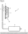
- the in FIG. 1 shown level sensor 1 is arranged in a fuel tank 2.
- the level sensor 1 consists of a pivotally mounted lever arm 3, at one end of a float 4 is mounted.
- the level sensor 1 further has a ceramic carrier plate 5, on which an electrical resistance network 6 is applied.
- a deflectable by the lever arm 3 by means of a magnet 7 contact structure 8 generates a function of the Hebelarm ein electrical signal for the level.
- the support plate 5 is connected to a cover 9 to form a housing 10 such that the resistance network 6 and the contact structure 8 are sealed from the environment.
- FIG. 2 shows the cover 9 and support plate 5 existing housing 10 of the level sensor.
- the lid 9 Parallel to the largest longitudinal extent of the housing 10, the lid 9 has two beads 11 for mechanical reinforcement.
- the beads 9 are arranged on the top cover 12.
- the beads 11 are curved in the direction of the interior of the housing, so that the cover 9 requires no larger space than an unreinforced cover.
- the in FIG. 3 shown cover 9 also has beads 11 to increase the mechanical stiffness.
- the beads 11 are arranged between the side surfaces 13 and the edge 14 of the lid.
Landscapes
- Physics & Mathematics (AREA)
- Fluid Mechanics (AREA)
- General Physics & Mathematics (AREA)
- Level Indicators Using A Float (AREA)
- Measurement Of Levels Of Liquids Or Fluent Solid Materials (AREA)
Description
- Gegenstand der Erfindung ist ein Füllstandsensor für einen Kraftstofftank, bestehend aus einer keramischen Trägerplatte mit einem darauf angeordneten Widerstandsnetzwerk und einer Kontaktstruktur zur Ermittlung eines elektrischen Signals für den Füllstand und einem mit der Trägerplatte verbundenen Deckel, wobei Deckel und Trägerplatte ein Gehäuse bilden.
- Das Gehäuse derartiger Sensoren dient zur Aufnahme diverser Bauteile des Sensors, um sie gegen aggressive Medien zu schützen. Bei einem Einsatz des Sensors in einem Kraftstofftank muss das Gehäuse in erster Linie kraftstoffbeständig und flüssigkeitsdicht sein. Dazu ist es bekannt, einen dünnwandigen Deckel aus Metall zu verwenden, der neben der flüssigkeitsdichten Ausbildung des Gehäuses gleichzeitig einen ausreichenden Schutz gegen die im Betrieb des Kraftstoffbehälters auftretenden Drücke im Bereich von 70-100 mbar formbeständig ist. In dem Dokument
DE 29700625 U1 ist ein Füllstandsgeber für den Tank eines Kraftfahrzeuges beschrieben, bei welchem ein Widerstandsnetzwerk an einem feststehenden Träger angeordnet ist, wobei am Widerstandsnetzwerk entsprechend der Position eines dem Niveau einer Flüssigkeit folgenden Schwimmers ein Ausgangssignal abnehmbar ist. - Sofern der Füllstandsensor nicht im fertigen Kraftstoffbehälter, sondern bereits zuvor in einen den späteren Kraftstoffbehälter bildenden Kunststoffvorformling eingebracht wird, kann der Füllstandsensor während des Herstellprozesses des Kraftstoffbehälters wesentlich höheren Drücken im Bereich von 8 bar bis 12 bar ausgesetzt werden. Infolge dieser hohen Drücke kommt es zu Verformungen des Deckels und der Trägerplatte, die wiederum zum Bruch der Trägerplatte führen, wodurch die Dichtheit des Gehäuses nicht mehr gewährleistet ist.
- Der Erfindung liegt daher die Aufgabe zugrunde, einen Füllstandsensor zu schaffen, der neben der Beständigkeit gegenüber den Einflüssen seines Einsatzortes auch gegenüber einer Vormontage mit erschwerten Umwelteinflüssen beständig ist.
- Erfindungsgemäß wird die Aufgabe dadurch gelöst, dass der Deckel mindestens eine Sicke aufweist, und dass die Sicken zwischen einer Seitenwand und dem Rand des Deckels ausgebildet sind.
- Durch die Anordnung von Sicken im Deckel wird in besonders einfacher Weise eine mechanische Verstärkung des Gehäuses und somit eine größere Beständigkeit des Deckels gegen Verformungen erreicht, die wiederum dazu führt, dass die Trägerplatte fester gelagert wird, wodurch sie auch bei größeren auf das Gehäuse einwirkenden Drücken weniger verformt und somit nicht beschädigt wird und die Dichtheit des Gehäuses erhalten bleibt. Ein zusätzlicher Materialeinsatz zur Verstärkung des Gehäuses ist dabei nicht notwendig. Da die Verstärkung lediglich auf den Deckel bezogen ist, können restlichen Bestandteile des Füllstandsgebers unverändert weiter benutzt werden. Die Verstärkung des Deckels bewirkt jedoch nicht nur einen Schutz bei großen Drücken, sondern auch bei gegenüber Normaldruck sehr kleinen Drücken.
- Neben der nachträglichen Ausbildung der Sicken in dem Gehäuse können diese aber auch im selben Arbeitsschritt mit der Gehäuseherstellung erzeugt werden. Diese Ausgestaltung hat den Vorteil, dass kein zusätzlicher Bearbeitungsschritt notwendig ist. Ermöglicht wird dies durch ein entsprechend gestaltetes Formwerkzeug für das Gehäuse.
- Eine besonders große mechanische Steifigkeit wird dadurch erreicht, dass alle Flächen des Deckels mit Sicken versehen sind. Es hat sich jedoch gezeigt, dass die Verstärkung einzelner Bereiche des Deckels bereits ausreichend ist. Eine Verstärkung des gesamten Gehäuses ist daher nicht notwendig, wodurch der Aufwand für die Verstärkung des Gehäuses gering ist.
- Als besonders stabil haben sich nichterfindungsgemäße Beispiele von Deckel herausgestellt, die lediglich an der Deckeloberseite Sicken aufweisen. Da die Deckeloberseite die größte Fläche des Deckels ist, wird mit der Anordnung von Sicken an dieser Fläche bereits eine gute Verstärkung des Gehäuses erreicht.
- Die Anzahl der Sicken an der Gehäuseoberseite lässt sich gering halten, wenn die Sicken parallel zur längsten Ausdehnung des Gehäuses ausgerichtet sind.
- Das Gehäuse des Füllstandsensors erfordert keinen größeren Bauraum, wenn die Sicken in Richtung des Gehäuseinneren gewölbt sind. Eventuell notwendige Anpassungen der Aufnahme für das Gehäuse sind daher nicht notwendig.
- Eine erfindungsgemäße Ausgestaltung besteht darin, die Sicken zwischen einer Seitenwand des Deckels und dem Randbereich anzuordnen. Mit dieser Ausbildung wird der Seitenwandbereich des Gehäuses verstärkt, so dass ein Durchbiegen des Gehäuses entlang der Seitenwände vermieden wird. Die Anzahl der vorzusehenden Sicken hängt von den auftretenden Belastungen ab.
- Ein zuverlässiger Schutz des Gehäuses gegen besonders starke Belastungen wird dadurch erreicht, dass die Anordnung von Sicken zwischen den Seitenwänden und dem Randbereich mit der Anordnung von Sicken in der Deckeloberseite kombiniert wird.
- An zwei Ausführungsbeispielen wird die Erfindung näher erläutert. Dabei zeigen:
- Figur 1:
- einen unverstärkten Füllstandssensor in einem Kraftstoffbehälter,
- Figur 2:
- das Gehäuse eines nichterfindungsgemäßen Füllstandsensors nach
Figur 1 in einer perspektivischen Ansicht und - Figur 3:
- eine erfindungsgemäße Ausführungsform des Deckels.
- Der in
Figur 1 dargestellte Füllstandsensor 1 ist in einem Kraftstoffbehälter 2 angeordnet. Der Füllstandsensor 1 besteht aus einem schwenkbar gelagerten Hebelarm 3, an dessen einen Ende ein Schwimmer 4 gelagert ist. Der Füllstandsensor 1 besitzt weiterhin eine keramische Trägerplatte 5, auf der ein elektrisches Widerstandsnetzwerk 6 aufgebracht ist. Eine von dem Hebelarm 3 mittels eines Magneten 7 auslenkbare Kontaktstruktur 8 erzeugt ein in Abhängigkeit von der Hebelarmstellung elektrisches Signal für den Füllstand. Die Trägerplatte 5 ist mit einem Deckel 9 unter Bildung eines Gehäuses 10 derart verbunden, dass das Widerstandsnetzwerk 6 und die Kontaktstruktur 8 gegenüber der Umgebung abgedichtet sind. -
Figur 2 zeigt das aus Deckel 9 und Trägerplatte 5 bestehende Gehäuse 10 des Füllstandsensors. Parallel zur größten Längsausdehnung des Gehäuses 10 weist der Deckel 9 zwei Sicken 11 zur mechanischen Verstärkung auf. Die Sicken 9 sind auf der Deckeloberseite 12 angeordnet. Die Sicken 11 sind dabei in Richtung des Gehäuseinneren gewölbt, so dass der Deckel 9 keinen größeren Bauraum als ein unverstärkter Deckel benötigt.
Der inFigur 3 dargestellte Deckel 9 besitzt ebenfalls Sicken 11 zur Erhöhung der mechanischen Steife. Die Sicken 11 sind zwischen den Seitenflächen 13 und dem Rand 14 des Deckels angeordnet.
Claims (1)
- Füllstandsgeber für einen Kraftstofftank, bestehend aus einer keramischen Trägerplatte mit einem darauf angeordneten Widerstandsnetzwerk und einer Kontaktstruktur zur Ermittlung eines elektrischen Signals für den Füllstand und einem mit der Trägerplatte verbundenen topfförmigen Deckel mit einer Deckeloberseite, mit einem nach außen weisenden, umlaufenden Rand und daran angrenzenden Seitenflächen, wobei Deckel und Trägerplatte ein Gehäuse bilden, indem der Rand des Deckels auf der Trägerplatte aufliegt, dadurch gekennzeichnet, dass der Deckel (9) mindestens eine Sicke (11) aufweist, und dass die Sicken (11) zwischen einer Seitenwand (13) und dem Rand (14) des Deckels (9) ausgebildet sind.
Applications Claiming Priority (1)
| Application Number | Priority Date | Filing Date | Title |
|---|---|---|---|
| DE102005029788A DE102005029788A1 (de) | 2005-06-24 | 2005-06-24 | Füllstandssensor |
Publications (3)
| Publication Number | Publication Date |
|---|---|
| EP1736743A2 EP1736743A2 (de) | 2006-12-27 |
| EP1736743A3 EP1736743A3 (de) | 2007-02-21 |
| EP1736743B1 true EP1736743B1 (de) | 2019-08-14 |
Family
ID=37023019
Family Applications (1)
| Application Number | Title | Priority Date | Filing Date |
|---|---|---|---|
| EP06112865.8A Ceased EP1736743B1 (de) | 2005-06-24 | 2006-04-21 | Füllstandsensor |
Country Status (3)
| Country | Link |
|---|---|
| US (1) | US20060288778A1 (de) |
| EP (1) | EP1736743B1 (de) |
| DE (1) | DE102005029788A1 (de) |
Families Citing this family (3)
| Publication number | Priority date | Publication date | Assignee | Title |
|---|---|---|---|---|
| DE102013219635B4 (de) | 2013-09-27 | 2022-04-14 | Vitesco Technologies GmbH | Einrichtung zur Einführung einer gefrierfähigen Flüssigkeit in das Abgassystem eines Kraftfahrzeuges |
| DE102016213501A1 (de) * | 2016-07-22 | 2018-01-25 | Continental Automotive Gmbh | Füllstandsgeber |
| US10689834B2 (en) | 2017-03-06 | 2020-06-23 | Bingham & Taylor Corp. | Meter pit and method of manufacturing the same |
Citations (8)
| Publication number | Priority date | Publication date | Assignee | Title |
|---|---|---|---|---|
| GB597974A (en) * | 1945-10-10 | 1948-02-06 | Smith Meters Ltd | Improvements in and relating to gas meters |
| DE2121823A1 (de) * | 1970-05-11 | 1971-11-25 | Lee Radke Associates Inc., Detroit, Mich. (V.StA.) | Kraftstofftank |
| US3913400A (en) * | 1974-04-10 | 1975-10-21 | Mueller Co | Plastic meter box |
| DE3926359A1 (de) * | 1988-08-09 | 1990-02-15 | Horst Wilms | Gehaeuse, insbesondere rolladenkasten |
| DE29700625U1 (de) * | 1997-01-16 | 1997-03-13 | VDO Adolf Schindling AG, 60326 Frankfurt | Füllstandsgeber |
| JP2000219162A (ja) * | 1999-02-01 | 2000-08-08 | Unipres Corp | 自動車の車体メンバー部材 |
| DE10229795A1 (de) * | 2002-07-03 | 2004-01-15 | Invensys Metering Systems Gmbh Ludwigshafen | Flüssigkeitszähler mit einem Gehäuse aus Kunststoff |
| JP2005103613A (ja) * | 2003-09-30 | 2005-04-21 | Kobe Steel Ltd | 自動車用ハットチャンネル型部材 |
Family Cites Families (14)
| Publication number | Priority date | Publication date | Assignee | Title |
|---|---|---|---|---|
| US3173174A (en) * | 1961-05-10 | 1965-03-16 | Illinois Tool Works | Molding apparatus for rim structure of thin wall plastic container |
| US3403376A (en) * | 1964-11-12 | 1968-09-24 | Stewart Warner Corp | Fuel depletion alarm circuit utilizing bimetal |
| DE1969790U (de) * | 1967-07-29 | 1967-10-05 | Vdo Schindling | Schwimmerhebelgeber fuer eine elektrische fluessigkeitstandanzeige. |
| DE2656097A1 (de) * | 1975-12-12 | 1977-06-23 | Plessey Handel Investment Ag | Potentiometer |
| US4113095A (en) * | 1976-11-26 | 1978-09-12 | Van Dorn Company | Tray-type processed food containers |
| JP2931646B2 (ja) * | 1989-09-11 | 1999-08-09 | フォード モーター カンパニー | フロート機構および燃料検出アセンブリ |
| US5051719A (en) * | 1990-06-11 | 1991-09-24 | Ford Motor Company | Thick-film non-step resistor with accurate resistance characteristic |
| US5357815A (en) * | 1993-02-10 | 1994-10-25 | Rochester Gauges, Inc. | Magnetically driven gauge with voltage divider |
| AU3583895A (en) * | 1995-06-07 | 1996-12-30 | Rochester Gauges, Inc. | Liquid level gauge assembly including potentiometer with con ductive polymeric element |
| US5992679A (en) * | 1998-06-25 | 1999-11-30 | S. C. Johnson Home Storage, Inc. | Container Having a selectively detachable lid including an interrupted reinforcing bead |
| US6511288B1 (en) * | 2000-08-30 | 2003-01-28 | Jakel Incorporated | Two piece blower housing with vibration absorbing bottom piece and mounting flanges |
| US20050139003A1 (en) * | 2003-02-26 | 2005-06-30 | Rudolph Bergsma Trust | Hermetic fuel level sender |
| US7182574B2 (en) * | 2004-11-05 | 2007-02-27 | Fasco Industries, Inc. | Draft inducer blower with fastener retention |
| US7409860B2 (en) * | 2006-02-14 | 2008-08-12 | Ti Group Automotive Systems, L.L.C. | Fuel level measurement device |
-
2005
- 2005-06-24 DE DE102005029788A patent/DE102005029788A1/de not_active Ceased
-
2006
- 2006-04-21 EP EP06112865.8A patent/EP1736743B1/de not_active Ceased
- 2006-06-21 US US11/473,210 patent/US20060288778A1/en not_active Abandoned
Patent Citations (8)
| Publication number | Priority date | Publication date | Assignee | Title |
|---|---|---|---|---|
| GB597974A (en) * | 1945-10-10 | 1948-02-06 | Smith Meters Ltd | Improvements in and relating to gas meters |
| DE2121823A1 (de) * | 1970-05-11 | 1971-11-25 | Lee Radke Associates Inc., Detroit, Mich. (V.StA.) | Kraftstofftank |
| US3913400A (en) * | 1974-04-10 | 1975-10-21 | Mueller Co | Plastic meter box |
| DE3926359A1 (de) * | 1988-08-09 | 1990-02-15 | Horst Wilms | Gehaeuse, insbesondere rolladenkasten |
| DE29700625U1 (de) * | 1997-01-16 | 1997-03-13 | VDO Adolf Schindling AG, 60326 Frankfurt | Füllstandsgeber |
| JP2000219162A (ja) * | 1999-02-01 | 2000-08-08 | Unipres Corp | 自動車の車体メンバー部材 |
| DE10229795A1 (de) * | 2002-07-03 | 2004-01-15 | Invensys Metering Systems Gmbh Ludwigshafen | Flüssigkeitszähler mit einem Gehäuse aus Kunststoff |
| JP2005103613A (ja) * | 2003-09-30 | 2005-04-21 | Kobe Steel Ltd | 自動車用ハットチャンネル型部材 |
Also Published As
| Publication number | Publication date |
|---|---|
| US20060288778A1 (en) | 2006-12-28 |
| DE102005029788A1 (de) | 2007-01-11 |
| EP1736743A3 (de) | 2007-02-21 |
| EP1736743A2 (de) | 2006-12-27 |
Similar Documents
| Publication | Publication Date | Title |
|---|---|---|
| DE102005041022B4 (de) | Kraftstoffpumpeneinheit | |
| DE102005056607A1 (de) | Ultraschallsensor | |
| EP2252753A1 (de) | Kraftfahrzeug-türaussengriff mit einem sensormodul | |
| DE102009029248A1 (de) | Mikromechanisches System zum Erfassen einer Beschleunigung | |
| DE102007008560A1 (de) | Ultraschallsensor mit einer an einem Substrat angebrachten Vibrationseinrichtung | |
| EP2351059B1 (de) | Komponententräger für im wesentlichen elektrische bauelemente | |
| WO2015000460A1 (de) | Kraftfahrzeugtürverschluss | |
| EP2438417B1 (de) | Sensor | |
| DE102010018993B4 (de) | Ultraschallsensor, zugehöriges Herstellungsverfahren und Umfelderkennungssystem | |
| EP1736743B1 (de) | Füllstandsensor | |
| WO2000079513A1 (de) | Dämpfende halterung für das gehäuse eines ultraschallwandlers und verfahren zur herstellung | |
| EP2697461B1 (de) | Kraftfahrzeugtürschlossgehäuse | |
| DE102006042680A1 (de) | Drucksensor | |
| EP1736744B1 (de) | Füllstandsensor | |
| EP2862278B1 (de) | Annäherungserfassungsvorrichtung | |
| DE3644307C2 (de) | ||
| DE102005029786B4 (de) | Füllstandsensor | |
| DE9105851U1 (de) | Drucksensor | |
| DE102007049198A1 (de) | Kapazitiver Regensensor mit vergrößerter sensitiver Fläche | |
| DE102010004876B4 (de) | Füllstandsgeber | |
| DE102020206242A1 (de) | Mikromechanisches Bauteil für eine Sensor- oder Mikrofonvorrichtung | |
| EP1690042A2 (de) | Haushaltsgerät mit einer bedienleiste | |
| DE29501299U1 (de) | Montagerahmen für Sanitärkörper | |
| WO2020126153A1 (de) | Verfahren zur herstellung eines vereisungsrobusten drucksensors und vereisungsrobuster drucksensor | |
| DE10316723A1 (de) | Probenplatte zum Einbau in eine Gehäusestruktur |
Legal Events
| Date | Code | Title | Description |
|---|---|---|---|
| PUAI | Public reference made under article 153(3) epc to a published international application that has entered the european phase |
Free format text: ORIGINAL CODE: 0009012 |
|
| AK | Designated contracting states |
Kind code of ref document: A2 Designated state(s): AT BE BG CH CY CZ DE DK EE ES FI FR GB GR HU IE IS IT LI LT LU LV MC NL PL PT RO SE SI SK TR |
|
| AX | Request for extension of the european patent |
Extension state: AL BA HR MK YU |
|
| PUAL | Search report despatched |
Free format text: ORIGINAL CODE: 0009013 |
|
| AK | Designated contracting states |
Kind code of ref document: A3 Designated state(s): AT BE BG CH CY CZ DE DK EE ES FI FR GB GR HU IE IS IT LI LT LU LV MC NL PL PT RO SE SI SK TR |
|
| AX | Request for extension of the european patent |
Extension state: AL BA HR MK YU |
|
| 17P | Request for examination filed |
Effective date: 20070205 |
|
| 17Q | First examination report despatched |
Effective date: 20070403 |
|
| AKX | Designation fees paid |
Designated state(s): DE ES FR GB IT |
|
| RAP1 | Party data changed (applicant data changed or rights of an application transferred) |
Owner name: CONTINENTAL AUTOMOTIVE GMBH |
|
| STAA | Information on the status of an ep patent application or granted ep patent |
Free format text: STATUS: EXAMINATION IS IN PROGRESS |
|
| GRAP | Despatch of communication of intention to grant a patent |
Free format text: ORIGINAL CODE: EPIDOSNIGR1 |
|
| STAA | Information on the status of an ep patent application or granted ep patent |
Free format text: STATUS: GRANT OF PATENT IS INTENDED |
|
| INTG | Intention to grant announced |
Effective date: 20190129 |
|
| GRAS | Grant fee paid |
Free format text: ORIGINAL CODE: EPIDOSNIGR3 |
|
| RAP1 | Party data changed (applicant data changed or rights of an application transferred) |
Owner name: CPT GROUP GMBH |
|
| GRAA | (expected) grant |
Free format text: ORIGINAL CODE: 0009210 |
|
| STAA | Information on the status of an ep patent application or granted ep patent |
Free format text: STATUS: THE PATENT HAS BEEN GRANTED |
|
| REG | Reference to a national code |
Ref country code: DE Ref legal event code: R081 Ref document number: 502006016327 Country of ref document: DE Owner name: VITESCO TECHNOLOGIES GMBH, DE Free format text: FORMER OWNER: SIEMENS AKTIENGESELLSCHAFT, 80333 MUENCHEN, DE |
|
| AK | Designated contracting states |
Kind code of ref document: B1 Designated state(s): DE ES FR GB IT |
|
| REG | Reference to a national code |
Ref country code: GB Ref legal event code: FG4D Free format text: NOT ENGLISH |
|
| REG | Reference to a national code |
Ref country code: DE Ref legal event code: R096 Ref document number: 502006016327 Country of ref document: DE |
|
| RAP2 | Party data changed (patent owner data changed or rights of a patent transferred) |
Owner name: VITESCO TECHNOLOGIES GMBH |
|
| REG | Reference to a national code |
Ref country code: DE Ref legal event code: R081 Ref document number: 502006016327 Country of ref document: DE Owner name: VITESCO TECHNOLOGIES GMBH, DE Free format text: FORMER OWNER: CPT GROUP GMBH, 30165 HANNOVER, DE |
|
| PG25 | Lapsed in a contracting state [announced via postgrant information from national office to epo] |
Ref country code: ES Free format text: LAPSE BECAUSE OF FAILURE TO SUBMIT A TRANSLATION OF THE DESCRIPTION OR TO PAY THE FEE WITHIN THE PRESCRIBED TIME-LIMIT Effective date: 20190814 |
|
| PG25 | Lapsed in a contracting state [announced via postgrant information from national office to epo] |
Ref country code: IT Free format text: LAPSE BECAUSE OF FAILURE TO SUBMIT A TRANSLATION OF THE DESCRIPTION OR TO PAY THE FEE WITHIN THE PRESCRIBED TIME-LIMIT Effective date: 20190814 |
|
| REG | Reference to a national code |
Ref country code: DE Ref legal event code: R097 Ref document number: 502006016327 Country of ref document: DE |
|
| PLBE | No opposition filed within time limit |
Free format text: ORIGINAL CODE: 0009261 |
|
| STAA | Information on the status of an ep patent application or granted ep patent |
Free format text: STATUS: NO OPPOSITION FILED WITHIN TIME LIMIT |
|
| 26N | No opposition filed |
Effective date: 20200603 |
|
| GBPC | Gb: european patent ceased through non-payment of renewal fee |
Effective date: 20200421 |
|
| PG25 | Lapsed in a contracting state [announced via postgrant information from national office to epo] |
Ref country code: GB Free format text: LAPSE BECAUSE OF NON-PAYMENT OF DUE FEES Effective date: 20200421 |
|
| PGFP | Annual fee paid to national office [announced via postgrant information from national office to epo] |
Ref country code: DE Payment date: 20210430 Year of fee payment: 16 |
|
| REG | Reference to a national code |
Ref country code: DE Ref legal event code: R081 Ref document number: 502006016327 Country of ref document: DE Owner name: VITESCO TECHNOLOGIES GMBH, DE Free format text: FORMER OWNER: VITESCO TECHNOLOGIES GMBH, 30165 HANNOVER, DE |
|
| REG | Reference to a national code |
Ref country code: DE Ref legal event code: R084 Ref document number: 502006016327 Country of ref document: DE |
|
| PGFP | Annual fee paid to national office [announced via postgrant information from national office to epo] |
Ref country code: FR Payment date: 20220421 Year of fee payment: 17 |
|
| REG | Reference to a national code |
Ref country code: DE Ref legal event code: R119 Ref document number: 502006016327 Country of ref document: DE |
|
| PG25 | Lapsed in a contracting state [announced via postgrant information from national office to epo] |
Ref country code: DE Free format text: LAPSE BECAUSE OF NON-PAYMENT OF DUE FEES Effective date: 20221103 |
|
| PG25 | Lapsed in a contracting state [announced via postgrant information from national office to epo] |
Ref country code: FR Free format text: LAPSE BECAUSE OF NON-PAYMENT OF DUE FEES Effective date: 20230430 |