EP1738151B1 - Dissipateur thermique de rheometre rotatif - Google Patents
Dissipateur thermique de rheometre rotatif Download PDFInfo
- Publication number
- EP1738151B1 EP1738151B1 EP05724829.6A EP05724829A EP1738151B1 EP 1738151 B1 EP1738151 B1 EP 1738151B1 EP 05724829 A EP05724829 A EP 05724829A EP 1738151 B1 EP1738151 B1 EP 1738151B1
- Authority
- EP
- European Patent Office
- Prior art keywords
- heating
- rheometer
- heat spreader
- substantially cylindrical
- cooling assembly
- Prior art date
- Legal status (The legal status is an assumption and is not a legal conclusion. Google has not performed a legal analysis and makes no representation as to the accuracy of the status listed.)
- Expired - Lifetime
Links
Images


Classifications
-
- G—PHYSICS
- G01—MEASURING; TESTING
- G01N—INVESTIGATING OR ANALYSING MATERIALS BY DETERMINING THEIR CHEMICAL OR PHYSICAL PROPERTIES
- G01N11/00—Investigating flow properties of materials, e.g. viscosity, plasticity; Analysing materials by determining flow properties
- G01N11/10—Investigating flow properties of materials, e.g. viscosity, plasticity; Analysing materials by determining flow properties by moving a body within the material
- G01N11/14—Investigating flow properties of materials, e.g. viscosity, plasticity; Analysing materials by determining flow properties by moving a body within the material by using rotary bodies, e.g. vane
-
- G—PHYSICS
- G01—MEASURING; TESTING
- G01N—INVESTIGATING OR ANALYSING MATERIALS BY DETERMINING THEIR CHEMICAL OR PHYSICAL PROPERTIES
- G01N11/00—Investigating flow properties of materials, e.g. viscosity, plasticity; Analysing materials by determining flow properties
- G01N2011/0006—Calibrating, controlling or cleaning viscometers
- G01N2011/002—Controlling sample temperature; Thermal cycling during measurement
Definitions
- the present invention relates generally to rheometers, which are used to characterize materials by measuring the materials' viscosity, elasticity, shear thinning, yield stress, compliance and/or other material properties.
- Rotary rheometers, viscometers or viscosimeters are used to measure fluid or other properties of materials such as their viscosity by rotating, deflecting or oscillating a measuring object in a material, and measuring, for example, the torque required to rotate or deflect or oscillate the object within the material.
- rheometer shall mean rheometers, viscometers, viscosimeters and similar instruments that are used to measure the properties of fluid or similar (see list below) materials.
- measuring object shall mean an object having any one of several geometries, including, for example, cones, discs, vanes, parallel plates, concentric cylinders and double concentric cylinders.
- the materials may be liquids, oils, dispersions, suspensions, emulsions, adhesives, biological fluids such as blood, polymers, gels, pastes, slurries, melts, resins, powders or mixtures thereof. Such materials shall all be referred to generically as "fluids" herein. More specific examples of materials include asphalt, chocolate, drilling mud, lubricants, oils, greases, photoresists, liquid cements, elastomers, thermoplastics, thermosets and coatings.
- the measuring object may be made of, for example, stainless steel, anodized aluminum or titanium.
- U.S. Patents Nos. 5,777,212 to Sekiguchi et al. , 4,878,377 to Abel and 4,630,468 to Sweet describe various configurations, constructions and applications of rheometers.
- the fluid properties of materials are generally dependent on their temperature. For that reason, it is generally important that the temperature of the material being tested is known and is homogeneous. If the temperature of the material being tested were not homogeneous, the accuracy and validity of the measurement would be seriously compromised.
- the temperature of the fluid is generally accurately controlled, and is preferably made as homogeneous as possible, for example by using a fluid bath or a Peltier plate. Compared to a fluid bath, a Peltier plate temperature control system provides a more rapid heating and cooling of the sample, and is more economical, because it does not require an expensive controlled-temperature fluid circulator.
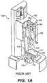
- Figure 1A is a schematic perspective view of a prior art rotary rheometer 100, showing lead screw 101, draw rod 102, optical encoder 103, air bearing 104, drive shaft 105, drag cup motor 106, measuring object 107 (shown in Figure 1A as a parallel plate), heating/cooling assembly (e . g ., a Peltier plate) 108, temperature sensor 110 (e.g., a Pt temperature sensor), surface 111, normal force transducer 112, and auto gap set motor and encoder 113.
- heating/cooling assembly e. g ., a Peltier plate
- temperature sensor 110 e.g., a Pt temperature sensor
- surface 111 e.g., normal force transducer 112
- auto gap set motor and encoder 113 e.g., a Pt temperature sensor
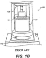
- Figure 1B is a schematic drawing of a concentric cylinder configuration in position on the rheometer of Figure 1A , showing the control jacket 120 of the concentric cylinder configuration on top of normal force transducer 112 of rheometer 100.
- Figure 1B shows a cylindrical measuring object 121 (used in this configuration instead of the parallel plate measuring object 107 shown in Figure 1A ).
- control jacket 120 contains a sample cup.
- the rheometer of Fig 1A relies solely on a Peltier heater 108 as the heat source to heat the sample from the bottom. Controlling the temperature from just one side of the sample in this manner can introduce error. As testing moves further away from ambient temperatures, error may increase due to the likelihood of increased temperature gradients. Increasing geometry gap as well as increasing temperature sensitivity of the sample may also increase error. For many applications, especially those occurring near ambient temperature, the error associated with single-side heating is insignificant.
- U.S. Pat. No. 6,572,610 One example of a prior art device that utilizes multi-station heating is disclosed in U.S. Pat. No. 6,572,610 . That disclosure teaches the use of an upper Peltier plate used in combination with a lower Peltier heating plate to achieve more uniform heating and cooling of a sample. Peltier plates may not, however, be the most desirable manner of heating the upper geometry of a rheometer. Such Peltier heating as disclosed in U.S. Pat. No. 6,572,610 can create a chimney effect whereby colder ambient air is drawn toward the heating element and exhausted out the top of the device. Such a flow of air can lead to undesirable cooling or simply affect heating of the sample such that the measurements taken become less accurate.
- the heat spreader of U.S. Pat. No. 6,572,610 moves relative to the upper Peltier heater as necessary to accommodate an increased or decreased sample gap. Because the heat spreader does not remain at a constant distance from the Peltier heater, the heating profile of the heat spreader, and thus the sample being tested, is constant changing. This constant difference in heating capability requires recalibration of the rheometer practically every time a new sample is tested. It would be desirable to have a rheometer with upper geometry heating capabilities that overcomes the drawbacks, such as chimney effect and sensitivity of the heat transfer function to geometry gap, of prior art rheometers.
- EP0138733 discloses a process of curing and testing rubber.
- WO2004017048 discloses a rheometer and a method of making rheological measurements.
- the present invention is a rotary rheometer having an upper assembly including active heating element(s) to heat the sample from more than just the bottom plate.
- One consideration in rheometer design is that there must be no contact between the upper heated plate assembly and the upper geometry heat spreader. The design, must therefore include an efficient method of transferring heat and cold. In the present invention, this is accomplished by placing heating elements in communication with a heat spreader to transfer the heat to the upper geometry.
- the upper heating assembly includes a pair of interlocked or mated elements that can be calibrated and employed to actively heat the sample gap from the above in addition to the lower heating plate.
- a further advantage of embodiments of the present invention is that their design is insensitive to changes in geometry gap or diameter, so calibration and recalibration is kept to a minimum.
- the temperature of the upper plate may further be modeled and the lower plate matched to it. Such matching causes the two plates to remain closely coupled during temperature ramps, thus meaning that the temperature displayed by the rheometer is that of both plates, not just the lower one.
- Fig. 2 is a perspective cut-away schematic diagram that shows an exemplary embodiment of the upper geometry heater of the present invention.
- rheometer 200 is similar in most functional rheometry aspects as prior art devices. It includes upper geometry 201, a Peltier plate heater 202, a lower heat spreader 204 for distributing the heat generated by heater 202 to sample gap 206, which is located between the upper geometry 201 of rheometer 200 and lower heat spreader 204.
- Above sample gap 206 is an upper heat plate assembly 208 comprising an inner portion 208a and an outer portion 208b. Inner portion 208a and outer portion 208b combine to form an inverted "U" shaped heating element.
- inner portions 208a and 208b may comprise a single unitary element or may comprise separate elements that may or may not be connected to one another.
- Upper heat plate assembly 208 fits over upper geometry heat spreader 210, which takes the shape of an upright "U".
- element 210 may also comprise a single unitary element or may comprise multiple elements that may or may not be physically connected to one another. Mating element 208 with element 210 in this fashion minimizes the chimney effect often encountered with prior art devices having upper geometry heating. Also, as described above, this configuration takes into account the design factor that elements 208a and 208b must not be in direct contact with upper geometry 201.
- upper heat plate assembly 208 and upper geometry heat spreader 210 maintain a constant relationship with upper geometry 201.
- heat plate assembly 208, upper geometry heat spreader 210, and upper geometry 201 all move together. In this manner, the heat transfer function from upper heat plate assembly 208 to upper heat spreader 210 and upper geometry 201 is always the same, thus eliminating the need for calibration of the device as sample gap is changed.
- Upper heat plate assembly 208 can advantageously be cooled by various methods depending on the temperature range required. Such cooling can be done by, for example, introduction of air, water, chilled fluid or vortex cooling. To aid in the cooling, assembly 208 further includes a cooling channel 212 for circulating a cooling fluid as described above. Cooling channel 212 is connected to coolant inlet 214 for introduction of an appropriate cooling fluid. Also, not pictured, rheometer 200 includes a cooling outlet for evacuation of the cooling fluid. An additional inlet 216 is provided for evacuation of inert gas.
- lower Peltier plate 202 can ramp up and down in temperature faster than that of upper assembly 208.
- the heating of the upper geometry may be modeled and then lower Peltier plate 202 can be matched so as to heat and cool in the same manner as upper assembly 208.
- Such matching between the two heat sources results in a minimization of temperature gradients during temperature ramps.
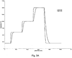
- Figs. 3A and 3B show graphical representations of upper and lower heating before and after calibration of lower Peltier plate 202 heating to the model of the upper plate heating assembly 208. As is shown, the two heating devices are nearly identical in Fig. 3B , thus greatly minimizing any temperature gradient between the two heating elements. Also, because any chimney effect is greatly reduced, if not eliminated, any temperature gradient of the sample is further reduced.
Landscapes
- Physics & Mathematics (AREA)
- Health & Medical Sciences (AREA)
- Life Sciences & Earth Sciences (AREA)
- Chemical & Material Sciences (AREA)
- Analytical Chemistry (AREA)
- Biochemistry (AREA)
- General Health & Medical Sciences (AREA)
- General Physics & Mathematics (AREA)
- Immunology (AREA)
- Pathology (AREA)
- Investigating Or Analyzing Materials Using Thermal Means (AREA)
- Devices For Use In Laboratory Experiments (AREA)
- Physical Or Chemical Processes And Apparatus (AREA)
- Centrifugal Separators (AREA)
Claims (10)
- Un rhéomètre (200) comprenant :un ensemble chauffage/refroidissement supérieur situé au-dessus d'un espace d'échantillon (206) ; etun ensemble chauffage/refroidissement inférieur situé sous l'espace d'échantillon (206),l'ensemble chauffage/refroidissement supérieur comprenant au moins un premier élément chauffant sensiblement cylindrique (208a, 208b) et un dissipateur thermique sensiblement cylindrique (210), l'un des au moins un premier élément chauffant sensiblement cylindrique (208a, 208b) ou du dissipateur thermique sensiblement cylindrique (210) étant positionné à l'intérieur de l'autre du dissipateur thermique sensiblement cylindrique (210) ou du au moins un premier élément chauffant sensiblement cylindrique (208a, 208b), et l'ensemble chauffage/refroidissement supérieur maintenant une relation constante avec une géométrie supérieure (201) de manière à ce que, en cours d'utilisation, quand l'espace d'échantillon (206) est changé, l'ensemble chauffage/refroidissement supérieur se déplace conjointement avec la géométrie supérieure (201).
- Le rhéomètre (200) de la revendication 1, comprenant en sus un espace formé entre l'élément chauffant sensiblement cylindrique (208a, 208b) et le dissipateur thermique sensiblement cylindrique (210).
- Le rhéomètre (200) de la revendication 1, l'ensemble chauffage/refroidissement supérieur comprenant en sus un deuxième élément chauffant sensiblement cylindrique, le dissipateur thermique sensiblement cylindrique (210) étant positionné à l'intérieur du deuxième élément chauffant sensiblement cylindrique.
- Le rhéomètre (200) de la revendication 3, comprenant en sus un espace formé entre le dissipateur thermique et le deuxième élément chauffant.
- Le rhéomètre (200) de la revendication 3, le premier et le deuxième élément chauffant comprenant un élément chauffant unique façonné en forme de U autour du dissipateur thermique.
- Le rhéomètre (200) de la revendication 5, comprenant en sus un espace formé entre l'élément chauffant unique façonné en forme de U et le dissipateur thermique.
- Le rhéomètre (200) de la revendication 1, comprenant en sus un espace formé entre l'élément chauffant sensiblement cylindrique et le dissipateur thermique sensiblement cylindrique.
- Le rhéomètre (200) de la revendication 1, l'ensemble chauffage/refroidissement inférieur correspondant sensiblement à un modèle de l'ensemble chauffage/refroidissement supérieur.
- Le rhéomètre (200) de la revendication 8, l'ensemble chauffage/refroidissement inférieur comprenant un élément chauffant Peltier (202).
- Le rhéomètre (200) de la revendication 1, comprenant en sus un canal de refroidissement (212) destiné à refroidir l'ensemble chauffage/refroidissement supérieur.
Applications Claiming Priority (3)
| Application Number | Priority Date | Filing Date | Title |
|---|---|---|---|
| US55133104P | 2004-03-10 | 2004-03-10 | |
| US11/075,338 US7168299B2 (en) | 2004-03-10 | 2005-03-09 | Heat spreader for rotary rheometer |
| PCT/US2005/007368 WO2005086769A2 (fr) | 2004-03-10 | 2005-03-10 | Dissipateur thermique de rheometre rotatif |
Publications (3)
| Publication Number | Publication Date |
|---|---|
| EP1738151A2 EP1738151A2 (fr) | 2007-01-03 |
| EP1738151A4 EP1738151A4 (fr) | 2012-04-04 |
| EP1738151B1 true EP1738151B1 (fr) | 2017-08-09 |
Family
ID=34922244
Family Applications (1)
| Application Number | Title | Priority Date | Filing Date |
|---|---|---|---|
| EP05724829.6A Expired - Lifetime EP1738151B1 (fr) | 2004-03-10 | 2005-03-10 | Dissipateur thermique de rheometre rotatif |
Country Status (3)
| Country | Link |
|---|---|
| US (1) | US7168299B2 (fr) |
| EP (1) | EP1738151B1 (fr) |
| WO (1) | WO2005086769A2 (fr) |
Families Citing this family (11)
| Publication number | Priority date | Publication date | Assignee | Title |
|---|---|---|---|---|
| US7776036B2 (en) * | 2003-03-13 | 2010-08-17 | Covidien Ag | Bipolar concentric electrode assembly for soft tissue fusion |
| DE102004050751B4 (de) * | 2004-10-16 | 2014-07-10 | Thermo Electron (Karlsruhe) Gmbh | Rheometer und Verfahren zur Temperierung seiner Messkammer |
| US20100071443A1 (en) * | 2008-09-25 | 2010-03-25 | Nathan Wrench | Temperature-controlled rheometer |
| WO2010111588A2 (fr) * | 2009-03-27 | 2010-09-30 | Ofi Testing Equipment, Inc. | Appareil et procédé de chauffage d'échantillon test |
| DE102010050973B4 (de) | 2010-11-10 | 2019-01-24 | Thermo Electron (Karlsruhe) Gmbh | Rheometer oder Viskosimeter |
| USD706658S1 (en) * | 2012-04-04 | 2014-06-10 | Thermo Electron Gmbh | Viscometer |
| DE102015100272B3 (de) * | 2015-01-09 | 2016-05-04 | Rheotec Messtechnik Gmbh | Temperieranordnung für Messgeräte |
| DE102015100278B3 (de) | 2015-01-09 | 2016-05-04 | Rheotec Messtechnik Gmbh | Temperieranordnung mit Kombinationswärmeübertrager zur Heizung und Kühlung einer Messplatte eines Messgerätes |
| CN110361298A (zh) * | 2018-05-11 | 2019-10-22 | 廊坊立邦涂料有限公司 | 一种流变仪 |
| WO2021242631A1 (fr) * | 2020-05-27 | 2021-12-02 | Ta Instruments-Waters Llc | Rhéomètre doté d'un dispositif de chauffage à résistance et d'un dispositif réfrigérant |
| AT525752B1 (de) * | 2022-01-28 | 2023-07-15 | Anton Paar Gmbh | Verfahren zur Messung der Viskosität einer Probe mit einem temperierbaren Rotationsrheometer und korrespondierende Vorrichtung |
Citations (1)
| Publication number | Priority date | Publication date | Assignee | Title |
|---|---|---|---|---|
| DE10058399A1 (de) * | 1999-11-29 | 2001-05-31 | Anton Paar Gmbh Graz | Rotationsrheometer |
Family Cites Families (10)
| Publication number | Priority date | Publication date | Assignee | Title |
|---|---|---|---|---|
| CA1200116A (fr) * | 1983-08-09 | 1986-02-04 | Ontario Research Foundation | Viscosimetre |
| US4552025A (en) * | 1983-09-06 | 1985-11-12 | Monsanto Company | Multifunction processability testing method and apparatus |
| US4546438A (en) | 1983-09-27 | 1985-10-08 | The Goodyear Tire & Rubber Company | Rheometer and process of curing and testing rubber |
| GB8525662D0 (en) * | 1985-10-17 | 1985-11-20 | Deer J J | Induction heating |
| JPH0772710B2 (ja) * | 1987-04-25 | 1995-08-02 | 日本合成ゴム株式会社 | 粘弾性測定装置 |
| US4878377A (en) * | 1988-10-07 | 1989-11-07 | Atlantic Richfield Company | Viscometer apparatus and method |
| JP2971025B2 (ja) * | 1996-03-01 | 1999-11-02 | 東機産業株式会社 | ばね緩和測定方法及びその方法を用いて試料液の流動特性を測定する回転式粘度計 |
| US6572610B2 (en) * | 2001-08-21 | 2003-06-03 | Cryogen, Inc. | Cryogenic catheter with deflectable tip |
| US6588254B1 (en) * | 2002-03-29 | 2003-07-08 | Waters Investment Limited | Rotary rheometer |
| AU2002950831A0 (en) | 2002-08-16 | 2002-09-12 | Gbc Scientific Equipment Pty Ltd | Rheometer |
-
2005
- 2005-03-09 US US11/075,338 patent/US7168299B2/en not_active Expired - Lifetime
- 2005-03-10 EP EP05724829.6A patent/EP1738151B1/fr not_active Expired - Lifetime
- 2005-03-10 WO PCT/US2005/007368 patent/WO2005086769A2/fr not_active Ceased
Patent Citations (1)
| Publication number | Priority date | Publication date | Assignee | Title |
|---|---|---|---|---|
| DE10058399A1 (de) * | 1999-11-29 | 2001-05-31 | Anton Paar Gmbh Graz | Rotationsrheometer |
Also Published As
| Publication number | Publication date |
|---|---|
| EP1738151A2 (fr) | 2007-01-03 |
| US20050199044A1 (en) | 2005-09-15 |
| EP1738151A4 (fr) | 2012-04-04 |
| US7168299B2 (en) | 2007-01-30 |
| WO2005086769A3 (fr) | 2006-11-16 |
| WO2005086769A2 (fr) | 2005-09-22 |
Similar Documents
| Publication | Publication Date | Title |
|---|---|---|
| EP1738151B1 (fr) | Dissipateur thermique de rheometre rotatif | |
| US6240770B1 (en) | Rotary viscosimeter | |
| US6588254B1 (en) | Rotary rheometer | |
| Callaghan et al. | A study of the “Spurt Effect" in wormlike micelles using nuclear magnetic resonance microscopy | |
| EP2205358B1 (fr) | Aspiration et distribution de petits volumes de liquides | |
| US9574983B2 (en) | Method of determining measurement data of samples and rheometer | |
| US10436694B2 (en) | Viscometer and methods for using the same | |
| EP0545728B1 (fr) | Rheomètre de cisaillement dynamique et sa méthode d'utilisation | |
| US8904852B2 (en) | Method for establishing rheometric parameters of samples and rotational rheometer | |
| US5209107A (en) | Capillary rheometer plunger pressure transducer and measurement technique | |
| US4173142A (en) | Rotary viscometer | |
| GB2359892A (en) | Rotary rheometer | |
| US4445365A (en) | Tapered bearing simulator-viscometer | |
| US5115669A (en) | Measuring shear viscosity of fluids | |
| US20240426727A1 (en) | Viscometer with reduced dead-volume and high dynamic range | |
| US20100139374A1 (en) | Methods for rheological testing of multiple samples and systems therefor | |
| US6708554B2 (en) | Rotational rheometer | |
| US7380442B2 (en) | On-line rotational/oscillatory rheometrical device | |
| Gregg et al. | A variable-volume optical pressure-volume-temperature cell for high-pressure cloud points, densities, and infrared spectra, applicable to supercritical fluid solutions of polymers up to 2 kbar | |
| US5540088A (en) | Rheometer and method of measuring rheological properties | |
| US20040099049A1 (en) | Rheometer | |
| EP3526580B1 (fr) | Viscosimètre et procédés d'utilisation de ce dernier | |
| US6427525B1 (en) | Viscosity sensor and regulator for continuously controlling a quenching bath | |
| US6666073B2 (en) | Apparatus for process line testing | |
| JP3679088B2 (ja) | 流通型磁気共鳴検出器 |
Legal Events
| Date | Code | Title | Description |
|---|---|---|---|
| PUAI | Public reference made under article 153(3) epc to a published international application that has entered the european phase |
Free format text: ORIGINAL CODE: 0009012 |
|
| 17P | Request for examination filed |
Effective date: 20060913 |
|
| AK | Designated contracting states |
Kind code of ref document: A2 Designated state(s): AT BE BG CH CY CZ DE DK EE ES FI FR GB GR HU IE IS IT LI LT LU MC NL PL PT RO SE SI SK TR |
|
| AX | Request for extension of the european patent |
Extension state: AL BA HR LV MK YU |
|
| DAX | Request for extension of the european patent (deleted) | ||
| RBV | Designated contracting states (corrected) |
Designated state(s): DE FR GB |
|
| A4 | Supplementary search report drawn up and despatched |
Effective date: 20120305 |
|
| RIC1 | Information provided on ipc code assigned before grant |
Ipc: G01N 11/14 20060101ALI20120228BHEP Ipc: G01N 11/00 20060101AFI20120228BHEP |
|
| RAP1 | Party data changed (applicant data changed or rights of an application transferred) |
Owner name: WATERS TECHNOLOGIES CORPORATION |
|
| 17Q | First examination report despatched |
Effective date: 20160520 |
|
| GRAP | Despatch of communication of intention to grant a patent |
Free format text: ORIGINAL CODE: EPIDOSNIGR1 |
|
| INTG | Intention to grant announced |
Effective date: 20170220 |
|
| GRAS | Grant fee paid |
Free format text: ORIGINAL CODE: EPIDOSNIGR3 |
|
| GRAA | (expected) grant |
Free format text: ORIGINAL CODE: 0009210 |
|
| AK | Designated contracting states |
Kind code of ref document: B1 Designated state(s): DE FR GB |
|
| REG | Reference to a national code |
Ref country code: GB Ref legal event code: FG4D |
|
| REG | Reference to a national code |
Ref country code: DE Ref legal event code: R096 Ref document number: 602005052489 Country of ref document: DE |
|
| REG | Reference to a national code |
Ref country code: DE Ref legal event code: R097 Ref document number: 602005052489 Country of ref document: DE |
|
| PLBE | No opposition filed within time limit |
Free format text: ORIGINAL CODE: 0009261 |
|
| STAA | Information on the status of an ep patent application or granted ep patent |
Free format text: STATUS: NO OPPOSITION FILED WITHIN TIME LIMIT |
|
| 26N | No opposition filed |
Effective date: 20180511 |
|
| PG25 | Lapsed in a contracting state [announced via postgrant information from national office to epo] |
Ref country code: FR Free format text: LAPSE BECAUSE OF NON-PAYMENT OF DUE FEES Effective date: 20180331 |
|
| P01 | Opt-out of the competence of the unified patent court (upc) registered |
Effective date: 20230612 |
|
| PGFP | Annual fee paid to national office [announced via postgrant information from national office to epo] |
Ref country code: DE Payment date: 20240220 Year of fee payment: 20 Ref country code: GB Payment date: 20240220 Year of fee payment: 20 |
|
| REG | Reference to a national code |
Ref country code: DE Ref legal event code: R071 Ref document number: 602005052489 Country of ref document: DE |
|
| REG | Reference to a national code |
Ref country code: GB Ref legal event code: PE20 Expiry date: 20250309 |
|
| PG25 | Lapsed in a contracting state [announced via postgrant information from national office to epo] |
Ref country code: GB Free format text: LAPSE BECAUSE OF EXPIRATION OF PROTECTION Effective date: 20250309 |