EP1738439B1 - Mechanisch unterstützter verbinder mit doppelwirkung - Google Patents
Mechanisch unterstützter verbinder mit doppelwirkung Download PDFInfo
- Publication number
- EP1738439B1 EP1738439B1 EP05734288A EP05734288A EP1738439B1 EP 1738439 B1 EP1738439 B1 EP 1738439B1 EP 05734288 A EP05734288 A EP 05734288A EP 05734288 A EP05734288 A EP 05734288A EP 1738439 B1 EP1738439 B1 EP 1738439B1
- Authority
- EP
- European Patent Office
- Prior art keywords
- housing
- sliding
- projection
- guide rail
- cam follower
- Prior art date
- Legal status (The legal status is an assumption and is not a legal conclusion. Google has not performed a legal analysis and makes no representation as to the accuracy of the status listed.)
- Expired - Lifetime
Links
- 230000009977 dual effect Effects 0.000 title description 4
- 230000013011 mating Effects 0.000 claims abstract description 45
- 238000000034 method Methods 0.000 claims description 21
- 239000007788 liquid Substances 0.000 claims description 3
- 230000035515 penetration Effects 0.000 claims 2
- 238000007789 sealing Methods 0.000 claims 1
- 230000008569 process Effects 0.000 description 10
- 230000000712 assembly Effects 0.000 description 6
- 238000000429 assembly Methods 0.000 description 6
- 230000007246 mechanism Effects 0.000 description 6
- 230000009471 action Effects 0.000 description 4
- 230000008901 benefit Effects 0.000 description 2
- 238000012986 modification Methods 0.000 description 2
- 230000004048 modification Effects 0.000 description 2
- 230000001681 protective effect Effects 0.000 description 2
- 230000004044 response Effects 0.000 description 2
- 239000004020 conductor Substances 0.000 description 1
- 210000003811 finger Anatomy 0.000 description 1
- 239000011810 insulating material Substances 0.000 description 1
- 239000012212 insulator Substances 0.000 description 1
- 230000003993 interaction Effects 0.000 description 1
- WABPQHHGFIMREM-UHFFFAOYSA-N lead(0) Chemical compound [Pb] WABPQHHGFIMREM-UHFFFAOYSA-N 0.000 description 1
- 239000000463 material Substances 0.000 description 1
- 238000004806 packaging method and process Methods 0.000 description 1
- 230000009467 reduction Effects 0.000 description 1
- 210000003813 thumb Anatomy 0.000 description 1
- 238000013024 troubleshooting Methods 0.000 description 1
Images




Classifications
-
- H—ELECTRICITY
- H01—ELECTRIC ELEMENTS
- H01R—ELECTRICALLY-CONDUCTIVE CONNECTIONS; STRUCTURAL ASSOCIATIONS OF A PLURALITY OF MUTUALLY-INSULATED ELECTRICAL CONNECTING ELEMENTS; COUPLING DEVICES; CURRENT COLLECTORS
- H01R13/00—Details of coupling devices of the kinds covered by groups H01R12/70 or H01R24/00 - H01R33/00
- H01R13/62—Means for facilitating engagement or disengagement of coupling parts or for holding them in engagement
- H01R13/629—Additional means for facilitating engagement or disengagement of coupling parts, e.g. aligning or guiding means, levers, gas pressure electrical locking indicators, manufacturing tolerances
-
- H—ELECTRICITY
- H01—ELECTRIC ELEMENTS
- H01R—ELECTRICALLY-CONDUCTIVE CONNECTIONS; STRUCTURAL ASSOCIATIONS OF A PLURALITY OF MUTUALLY-INSULATED ELECTRICAL CONNECTING ELEMENTS; COUPLING DEVICES; CURRENT COLLECTORS
- H01R13/00—Details of coupling devices of the kinds covered by groups H01R12/70 or H01R24/00 - H01R33/00
- H01R13/62—Means for facilitating engagement or disengagement of coupling parts or for holding them in engagement
- H01R13/629—Additional means for facilitating engagement or disengagement of coupling parts, e.g. aligning or guiding means, levers, gas pressure electrical locking indicators, manufacturing tolerances
- H01R13/62933—Comprising exclusively pivoting lever
- H01R13/62938—Pivoting lever comprising own camming means
-
- H—ELECTRICITY
- H01—ELECTRIC ELEMENTS
- H01R—ELECTRICALLY-CONDUCTIVE CONNECTIONS; STRUCTURAL ASSOCIATIONS OF A PLURALITY OF MUTUALLY-INSULATED ELECTRICAL CONNECTING ELEMENTS; COUPLING DEVICES; CURRENT COLLECTORS
- H01R13/00—Details of coupling devices of the kinds covered by groups H01R12/70 or H01R24/00 - H01R33/00
- H01R13/62—Means for facilitating engagement or disengagement of coupling parts or for holding them in engagement
- H01R13/629—Additional means for facilitating engagement or disengagement of coupling parts, e.g. aligning or guiding means, levers, gas pressure electrical locking indicators, manufacturing tolerances
- H01R13/62933—Comprising exclusively pivoting lever
- H01R13/62955—Pivoting lever comprising supplementary/additional locking means
Definitions
- the invention relates generally to electrical connector assemblies. More particularly, the invention relates to an electrical connector assembly with a lever mechanism to securely mate and un-mate the connectors with a reduced mating force as a cover housing and a lever housing are rotated.
- U.S. Pat. No. 6,217,354 appears to disclose an electrical connector with an actuating lever that is pivotally mounted to one side of the connector assembly.
- the actuating lever includes a cam groove.
- a slide member is mounted on the actuating lever and moves linearly as the actuating lever pivots.
- the slide member includes a cam follower projection that engages in the cam groove of the actuating lever.
- the slide member also has a second cam groove.
- the second side of the connector assembly has a second cam follower projection that engages in the second cam groove of the slide member.
- the slide member moves linearly relative to both sides of the connector as the cam follower projections engage the cam grooves, and the connector sides mate and un-mate in response to the lever action.
- the '354 patent fails to disclose means with which to suitably align the entire connector assembly during the mating action while simultaneously guarding against actuation of the cam mechanism when the connector is not properly mated.
- U.S. Pat. No. 5,938,458 appears to disclose an electrical connector assembly with an actuating lever pivotally mounted to a first connector.
- the actuating lever has a cam groove formed therein.
- a second connector has a cam follower projection to engage in the cam groove of the actuating lever.
- the connectors are mated and un-mated in response to the rotation of an actuating lever.
- the '458 patent fails to disclose means with which to suitably align the connectors prior to engaging the cam system as well as to overcome higher mating forces required by multi-pin and multipart connectors.
- U.S. Patent No. 5,681,175 is another example of an electrical connector that appears to employ a camming system for mating and unmating a pair of electrical connectors.
- the '175 patent discloses a lock slide member mounted on one of the housings and movable along a path transverse to the mating axis.
- the lock slide member includes one cam track, while the other housing has a cam follower projection. As the lock slide member is moved, the cam follower projection projects into the cam track, and the connectors are mated.
- the '175 patent employs a camming system, it fails to disclose means with which to suitably align the connectors during the mating process, and further fails to disclose a mechanism to overcome higher mating forces required in multi-pin and multipart connector applications.
- the slide mechanism of the '175 patent produces a significantly smaller mechanical advantage which may result in an inadequate applied mating force.
- the present invention relates to an electrical connector assembly and method for establishing and maintaining electrical contact between conductive members to be joined by employing a lever mechanism to securely mate and un-mate the connectors with a reduced mating force as a cover housing and a lever housing are rotated.
- the present invention provides a simple, powerful, and inexpensive electrical connector assembly to securely and confidently join male and female electrical connector structures to ensure electrical continuity and complete electrical circuits.
- No previous connector assembly employs a lever-type connector assembly with a slide lever housing employing a cam groove-cam follower projection coupled with sets of guide rails to ensure the mating forces are applied along the proper mating axis and are substantially constant during the mating process.
- the present lever-type electrical connector assembly invention reduces required connecting mating forces by employing a connector structure that includes two cam follower projections.
- the housing assembly includes a base housing for receiving the connector structure.
- the base housing includes two cam grooves and a sliding guide rail.
- a slide lever housing is mounted on the base housing.
- the slide lever housing includes a sliding projection engaged in a sliding guide rail.
- the slide lever housing also has a second sliding guide rail that receives a second sliding projection that is part of a cover housing.
- the cover housing is pivotally mounted on the base housing.
- the present invention eliminates alignment errors while simultaneously reducing the required mating forces by means of a lever assembly and camming system that provides a dual action mechanical assist to establish an intimate electrical connection between male and female connector structures.
- the present invention employs a novel cam groove geometry that results in mating forces that are substantially constant throughout the mating operation.
- the method of the present invention allows users to securely and reliably mate connectors with large numbers of pins and high mating forces, while at the same time preventing alignment errors, eliminating intermittent connections, and improving reliability of the overall product.
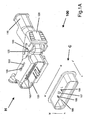
- Figure 1A is a perspective view of the connector assembly in accordance with the present invention in a fully unmated state.
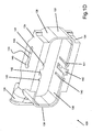
- Figure 1B is perspective view of the cover housing of the present invention.
- Figure 1C is perspective view of the lever housing of the present invention.
- Figure 1D is a perspective view of the base housing of the present invention.
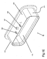
- Figure 1E is a perspective view of the mating connector of the present invention.
- Figure 2A is a perspective view of the connector housing just prior to beginning the mating process.
- Figure 2B is a perspective view of the connector housing showing the applied forces of the cover housing and the lever housing as the cover housing is rotated toward a mated state.
- Figure 3 is a perspective view of the connector housing showing the cover housing in a fully closed position and showing an expanded view of a first sliding projection.
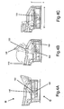
- Figure 4A is a perspective view of the connector assembly just prior to rotation of the lever housing.
- Figure 4B is a perspective view depicting the connector assembly as the lever housing is in the process of being rotated.
- Figure 4C is a perspective view showing the lever housing fully rotated and the connector assembly in its fully mated state.
- the present invention extends the functionality of current electrical connector assemblies by properly and consistently aligning multi-pin connectors and joining the structures with reduced mating forces. Once joined, the electrical connector assembly of the present invention is secured using the lever housing to ensure that the connection does not loosen or otherwise disconnect over time. This has many advantages over prior assemblies such as those providing simple cam slides, because the dual action mechanical assistance provided by the present invention significantly reduces the required mating forces while providing improved alignment consistency and reliability by way of the sliding guide rails and the novel geometry of the cam grooves.
- FIG 1A illustrates connector assembly 100 in a fully unmated state.
- housing H of the connector assembly 100 includes the dual action mechanical assist mechanism of the present invention, and that the individual male and female connector structures may be reversed between housing H and connector C without changing the overall structure of connector assembly 100 of the present invention.
- housing H and connector C structures as depicted in Figure 1A .
- the particular components of the housing H and connector C are illustrated in detail in Figures 1B-1E .
- Figure 1A shows housing H and connector C.
- electrical contact points 195 are formed through in the front to rear direction of connector C as illustrated by directional line z—z'
- the electrical contact points 195 are formed parallel to each other in several rows in the height direction of the connector C as illustrated by directional line h—h' and in several columns in the width direction of the connector C as illustrated by directional line w—w'.
- An electric wire W (not shown) is connected to each electrical contact point 195.
- chambers 190 are formed in a reciprocal fashion to accommodate the type of electrical contact point 195 utilized in connector C.
- the electrical contact points 195 may be made in any number of ways, including, but not limited to blade terminals, pin terminals, block terminals, edge connectors, and the like, as long as the chambers 190 on housing H and electrical contact points 195 on connector C form the two halves of the physical junction that join to complete an electrical circuit.
- Connector C also includes first cam follower projection 165 and second cam follower projection 166. Similarly, two corresponding cam follower projections are present on the underside of connector C (not shown), along the h—h' axis so that there are a total of two pairs of cam follower projections on connector C.
- Housing H is made of an insulating material and forms the reciprocal side of connector assembly 100 and comprises a base housing 130.
- Base housing 130 best illustrated in Figure 1D , has a first sliding guide rail 133 formed to accept a first sliding projection 150.
- First sliding projection 150 is formed as part of lever housing 120, as shown in Figure 1C .
- Lever housing 120 is formed to also include a first cam groove 152, a second cam groove 154, and second sliding guide rails 122 which accept second sliding projections 160.
- the second sliding projections 160 are formed as part of cover housing 110, one such projection illustrated in Figure 1B , with the second projection extending from the opposing side of cover housing 110.
- Cover housing 110 is pivotally mounted on the base housing 130 and forms a protective cover shielding the point of electrical contact between connector C and housing H in connector assembly 100 as does back wall 126 of the lever housing 120.
- connector C and housing H may also be lined with a flexible impervious material to prevent liquid and vapor from reaching the electrical connection point of contact.
- each of the four components which make up the connector assembly 100 are separately illustrated.
- the components include connector C and cover housing 110, lever housing 120, and base housing 130 combining to form housing H.
- the cover housing 110 forms a protective cover shielding the electrical connections made between the housing H and connector C as do side walls 124 and back wall 126 of the lever housing 120.
- cover housing 110 is a three-sided housing having sidewalls 112 and a back wall 114. Each of the sidewalls 112 include one of the projections 160 each being received in one of the second sliding guide rails 122 of the lever housing 120.
- lever housing 120 similarly includes two side walls 124 and a back wall 126.
- the back wall 126 includes ridges 128 which aid the user in engaging the lever housing 120 such that during pivoting of the lever housing 120, the finger or thumb of the user does not readily slip off the lever housing.
- the side walls 124 of the lever housing 120 are substantially planar with sliding projections 150 extending from each of the side walls 124. The thickness of the sidewall 124 is such that it can be readily received by the base housing 130. While the particular configuration of the lever housing 120 is not critical, the functionality of such is as noted hereinbelow.
- one side wall 124 includes first cam groove 152 formed on an inside surface thereof while the opposing sidewall includes second cam groove 154.
- the cam grooves 152 and 154 are mirror images of one another and include lead-in portions 156 and arched portions 158. The significance of the arched portions is explained in greater detail hereinbelow.
- the base housing 130 includes the first guide rails 133 formed in each of the wing walls 134, which extend substantially parallel to and spaced from a respective sidewall 136 of the base housing 130.
- the configuration of the first guide rails 133 includes an elongated section 146 and a circular section 145, the significance of which will be discussed in greater detail hereinbelow.
- the base housing 130 also includes end walls 137 and 138 with end wall 138 including a lead portion 139 for cooperating with the cover housing 110 in forming an opening to the housing H for receiving a lead wire, not shown.
- each of the side walls 136 includes substantially parallel guide rails 140, 141, 142 for receiving the projections 165, 166, and 167 of connector C.
- Guide rails 140 and 141 extending alongside guide rail 142 for receiving projections 165 and 166 aiding in the proper alignment of the connector C with respect to the base housing 130.
- the connector C includes side walls 169 and 170 and end walls 171 and 172 with the projections 165, 166, and 167 extending from a substantially center region of each of the side walls 169 and 170, the connector C being sized to be slidingly received within the base housing 130.
- the projections 165 and 166 extending outwardly a distance less than the thickness of side walls 136 of the base housing 130 while the center projection 167 extends a distance greater than the thickness of the sidewalls 136 so as to extend into the space formed between the sidewalls 136 and wing walls 134 of the base housing 130. This is so that the projections 167 can be received by the first and second cam grooves 152 and 154 of the lever housing 120. This interaction will be described in greater detail hereinbelow.
- Figure 2A illustrates connector assembly 100 in a fully unmated state. That is, connector C is not inserted in housing H.
- Figure 2A shows housing H as it is activated to begin the mating process.
- connector C is not shown in Figures 2A and 2B , but it should be understood that connector C is partially inserted in housing H prior to the method of practicing the present invention of mating the two structures of connector assembly 100. This arrangement is shown in Figures 4A, 4B, and 4C .
- Fig. 2A illustrates the housing H in a fully open state, where the housing H is initially assembled, the cover housing 110 is received within the side walls 124 and in front of the end wall 126 of the lever housing 120 and the second sliding projections 160 of the cover housing are received in the second slide rails 122 of the lever housing 120 and the side walls 124 of the lever housing 120 are received in the space formed between the wing walls 134 and the sidewalls 136 of the base housing. Further, the sliding projections 150 of the lever housing are received in the respective first guide rails formed in the wing walls 134 of the base housing 130.
- cover housing 110 and the base housing 130 are hingedly connected to one another and may be integrally formed with one another. Alternatively, the back wall 114 of the cover housing 110 may otherwise engage the end wall 137 of the base housing 130 to form a pivot point therebetween.
- cover housing 110 and lever housing 120 In its fully-opened position, as shown in Fig. 2A , cover housing 110 and lever housing 120 significantly form housing H so as to provide improved access to chambers 190 in base housing 130.
- This improved access to chambers 190 in the housing's fully-opened position facilitates faster and more efficient assembly of housing H, including population of chambers 190 with reciprocal electrical contact points with which to form the physical junction that joins with electrical contact points 195 in connector C.
- the novel geometry formed by the combination of cover housing 110 and lever housing 120 provide improved access while minimizing the total package area.
- Fig. 2B shows housing H with cover housing 110 fully-opened to begin the mating process.
- Cover housing 110 is set to its fully-opened state in the base housing 130.
- Cover housing 110 is pivotally mounted on base housing 130 and will rotate from its fully open state toward base housing 130 along directional arc a—a' during mating.
- second sliding projections 160 exert pressure on second sliding guide rail 122 with force components generally in the width direction of the housing and in the front-to-rear direction of the housing H.
- the width direction is shown in Fig. 2B as directional line b—b' and the front-to-rear direction is shown in Fig. 2B as directional line c—c'.
- the corresponding force arrows in the appropriate directions are also shown.
- second sliding projection 160 The pressure exerted by second sliding projection 160 on second sliding guide rail 122 causes lever housing 120 to move linearly in the width direction along line b—b'.
- second sliding projection 160 moves linearly along direction line b—b' until first sliding projection 150 encounters a mechanical stop indicating the end point of travel 145 in first sliding guide rail 133.
- This mechanical stop at the end point of travel 145 is in base housing 130 in a position along direction line b—b' corresponding to the end of the full range of angular motion of cover housing 110.
- cover housing 110 is in its fully closed position corresponding to the end of travel along arc a—a', and first sliding projection 150 of lever housing 120 is at the end of linear travel along direction line b—b'.
- sliding projection 150 reaches the end of linear travel, lever housing 120 no longer extends beyond the edges of base housing 130 and connector C. In this mated fully-closed position, total packaging size of the connector assembly 100 is minimized, thereby providing improved clearance in environments where the connector assembly 100 is utilized.
- first sliding projection 150 has traveled the full range of linear motion in first sliding guide rail 133
- lever housing 120 has traveled its full range of linear motion along direction line b—b' as well.
- An enlargement of first sliding projection 150 in this position is shown in expanded view V.
- the shape of first sliding projection 150 is substantially a rounded rectangle.
- the shape of the end point of travel 145 of first sliding guide rail 133 is substantially circular.
- the length of the diagonal d—d' of first sliding projection 150 is slightly smaller than the diameter of end point of travel 145, and the width of the first sliding projection 150 is slightly less than a width of the elongated portion 146 of the first sliding rail 133 to restrict the pivoting of the lever housing 120 with respect to the base housing 130 during the linear travel of the lever housing 120.
- lever housing 120 is rotated in substantially the same direction as cover housing 110 was rotated along arc a—a' as was depicted in Fig. 2B .
- the geometry of the first sliding projection 150 and the end point of travel 145 permits first sliding projection 150 to rotate within the circumference of end point of travel 145 shown as directional arc J—J'.
- the connector is secured since first sliding projection 150 cannot back out of end point of travel 145 because the length of first sliding projection 150 is greater than that of the opening.
- Rotation of both lever housing 120 and first sliding projection 150 stop when lever housing 120 completes the rotational arc substantially along arc J—J' and meets a mechanical stop such as closed cover housing 110.
- first cam groove 154 on lever housing 120 engages first cam follower projection 167 on connector C and second cam groove 152 engages second cam follower projection (not shown, but on the opposite side of connector C).
- first cam groove 154 and second cam groove 152 are substantially circular arcs, and as such provide a substantially constant force in the z—z' mating direction when lever housing 120 is rotated.
- first cam groove 154 engages first cam follower projections 167
- second cam groove 152 engages the second cam follower projection. This action drives first cam follower projection 167 and second cam follower projection in the z—z' direction.
- the circular camming action of the cam grooves draws connector C and housing H together into a mated condition by exerting a substantially constant force in the z—z' direction.
- This substantially constant force along with the guide rails 140, 141 and projections 165, 166, facilitates proper alignment of connector C and housing H as the structures are mated.
- Figs. 4A, 4B, and 4C the housing H is shown in three positions as the lever housing 120 is rotated.
- first sliding projection 150 has reached the end point of travel 145, but lever housing 120 has not yet started to rotate.
- lever housing 120 is in the process of being rotated along arc J—J', thereby rotating first sliding projection 150.
- first cam groove 154 receives and engages first cam follower projection 167 and the second cam groove 152 receives and engages the second cam follower projection on the opposite side of the connector C.
- the arc portion of cam grooves 152 and 154 are engaging cam follower projections 165 and 166 providing a force reduction.
- Fig. 4A first sliding projection 150 has reached the end point of travel 145, but lever housing 120 has not yet started to rotate.
- Fig. 4B lever housing 120 is in the process of being rotated along arc J—J', thereby rotating first sliding projection 150.
- first cam groove 154 receives and engages first cam follower projection 167
- lever housing 120 is fully rotated, and the connection is complete. As shown in Fig. 4C , when lever housing 120 is fully rotated, first sliding projection 150 is also fully rotated and due to its configuration serves as a locking device to hold the connector assembly in its final, secure position.
- lever housing 120 is rotated in the opposite direction toward its initial position. This, in turn, rotates first sliding projection 150 and returns first sliding projection 150 to an unlocked position allowing first sliding projection 150 to fit through and enter the opening of first sliding guide rail 133. Simultaneously, as lever housing 120 is further rotated, the rotation forces first cam follower projection 167 and second cam follower projection back along first cam groove 154 and the second cam groove 152, respectively. This disengaging of the cam followers from the cam grooves allows connector C to withdraw from housing H. When lever housing 120 is rotated back to its starting position, cover housing 110 may then be rotated back to its initial position as well.
- second sliding projection 160 exerts pressure on second sliding guide rail 122 with force components generally in the width direction w—w' of the housing and in the front-to-rear direction z—z' of the housing H.
- the width direction w—w' the front-to-rear direction, z—z' and the height direction h—h' are shown in Fig. 4A .
- second sliding projection 160 causes lever housing 120 to move linearly back toward its initial position.
- second sliding guide rail 122 moves back in the reverse direction until second sliding guide rail 122 encounters the end of travel in the reverse direction by encountering second sliding projection 160, which acts as a mechanical stop.
- cover housing 110 is once again in its fully open position and first sliding projection 150 and lever housing 120 have been returned to their initial ends of linear travel.
Landscapes
- Details Of Connecting Devices For Male And Female Coupling (AREA)
- Connector Housings Or Holding Contact Members (AREA)
Claims (13)
- Kipphebel-Elektro-Steckverbinderanordnung (100), die erforderliche Verbindungs-Paarungskräfte verringert, aufweisend:einen ersten Steckverbinder (C), der einen ersten Kurveneingriffsfortsatz (167) und einen zweiten Kurveneingriffsfortsatz aufweist;ein Basisgehäuse (130) zum Verbinden mit dem ersten Steckverbinder (C), wobei das Basisgehäuse (130) eine erste Führungsschiene (140 oder 141 oder 142), eine zweite Führungsschiene (140 oder 141 oder 142) und eine erste Gleitführungsschiene (133) aufweist;ein Gleithebelgehäuse (120), das an dem Basisgehäuse (130) angebracht ist und einen ersten Gleitfortsatz (150), der in der ersten Gleitführungsschiene (133) in Eingriff ist, einen ersten Nockenschlitz (154) zum Aufnehmen des ersten Kurveneingriffsfortsatzes (167) und einen zweiten Nockenschlitz (152) zum Aufnehmen des zweiten Kurveneingriffsfortsatzes aufweist, wobei das Gleithebelgehäuse (120) eine zweite Gleitführungsschiene hat; undein Abdeckungsgehäuse (110), das einen zweiten Gleitfortsatz (160) hat, der in der zweiten Gleitführungsschiene (122) in Eingriff ist, wobei das Abdeckungsgehäuse (110) schwenkbar an dem Basisgehäuse (130) angebracht ist.
- Kipphebel-Elektro-Steckverbinderanordnung (100) gemäß Anspruch 1, wobei die erste Gleitführungsschiene (133) einen seitlichen Anschlag zum Verhindern einer weiteren Verschiebung des ersten Gleitfortsatzes (150) aufweist.
- Kipphebel-Elektro-Steckverbinderanordnung (100) gemäß Anspruch 2, wobei der seitliche Anschlag der ersten Gleitführungsschiene (133) einen kreisförmigen Bereich aufweist, der dazu ausgebildet ist, einen Bereich dafür bereitzustellen, dass sich der erste Gleitfortsatz (150) drehen kann, während das Gleithebelgehäuse (120) von einer ungepaarten Position in eine gepaarte Position gedreht wird.
- Kipphebel-Elektro-Steckverbinderanordnung (100) gemäß Anspruch 1, wobei mindestens entweder der erste Nockenschlitz (154) oder der zweite Nockenschlitz (152) nicht linear ist, um mindestens entweder mit dem ersten Kurveneingriffsfortsatz (167) oder dem zweiten Kurveneingriffsfortsatz in Eingriff zu kommen, während das Gleithebelgehäuse (120) von einer ungepaarten Position in eine gepaarte Position gedreht wird.
- Kipphebel-Elektro-Steckverbinderanordnung (100) gemäß Anspruch 4, wobei der mindestens eine nicht lineare Nockenschlitz in der Form eines Bogens ausgebildet ist, wodurch eine im Wesentlichen konstante Paarungskraft bereitgestellt wird, während das Gleithebelgehäuse (120) von einer ungepaarten Position in eine gepaarte Position gedreht wird.
- Kipphebel-Elektro-Steckverbinderanordnung (100) gemäß Anspruch 1, wobei die Anordnung (100) abgedichtet ist, um das Eindringen von Flüssigkeit und Dampf zu verhindern.
- Kipphebel-Elektro-Steckverbinderanordnung (100) gemäß Anspruch 1, wobei das Abdeckungsgehäuse (110) von einer offenen Position in eine geschlossene Position gedreht wird, wodurch der zweite Gleitfortsatz (160) in der zweiten Gleitführungsschiene (122) in Eingriff kommt, um die Bewegung des Gleithebelgehäuses (120) von einer offenen in eine geschlossene Position zu gestatten, wodurch der erste Gleitfortsatz (150) in der ersten Gleitführungsschiene (133) in Eingriff kommt und wobei das Gleithebelgehäuse (120) von einer ungepaarten Position in eine gepaarte Position gedreht wird, wodurch der erste Nockenschlitz (154) und der zweite Nockenschlitz (152) gedreht werden, um mit dem ersten Kurveneingriffsfortsatz (167) und dem zweiten Kurveneingriffsfortsatz in Eingriff zu kommen, wodurch der erste Steckverbinder (C) in das Basisgehäuse (130) in eine verbundene Position gezogen wird.
- Verfahren zum Verriegeln eines Verbindungselements (C) in einen sicheren elektrischen Eingriff mit einem Gehäuseelement (H), wobei das Verfahren aufweist:Einführen des Verbindungselements (C) in das Gehäuseelement (H), wobei das Verbindungselement (C) einen ersten Kurveneingriffsfortsatz (167) und einen zweiten Kurveneingriffsfortsatz aufweist, und das Gehäuseelement (H) aufweist:ein Basisgehäuse (130), wobei das Basisgehäuse (130) eine erste Führungsschiene (140 oder 141 oder 142), eine zweite Führungsschiene (140 oder 141 oder 142) und eine erste Gleitführungsschiene (133) aufweist;ein Gleithebelgehäuse (120), das an dem Basisgehäuse (130) angebracht ist und einen ersten Gleitfortsatz (150) aufweist, der in der ersten Gleitführungsschiene (133) in Eingriff ist, einen ersten Nockenschlitz (154) zum Aufnehmen des ersten Kurveneingriffsfortsatzes (167) und einen zweiten Nockenschlitz (152) zum Aufnehmen des zweiten Kurveneingriffsfortsatzes, wobei das Gleithebelgehäuse (120) eine zweite Gleitführungsschiene (122) hat; undein Abdeckungsgehäuse (110), das einen zweiten Gleitfortsatz (160) hat, der in der zweiten Gleitführungsschiene (122) in Eingriff ist, wobei das Abdeckungsgehäuse (110) schwenkbar an dem Basisgehäuse (130) angebracht ist,Drehen des Gleithebelgehäuses (120) von einer offenen Position in eine geschlossene Position, wodurch der zweite Gleitfortsatz (160) in der zweiten Gleitführungsschiene (122) in Eingriff kommt;Verschieben des Gleithebelgehäuses (120) von einer offenen Position in eine geschlossene Position, wodurch der zweite Gleitfortsatz (150) in der zweiten Gleitführungsschiene (133) in Eingriff kommt;Drehen des Gleithebelgehäuses (120) von einer ungepaarten Position in eine gepaarte Position, wodurch der erste Nockenschlitz (154) und der zweite Nockenschlitz (152) gedreht werden, um mit dem ersten Kurveneingriffsfortsatz (167) und dem zweiten Kurveneingriffsfortsatz in Eingriff zu kommen, wodurch das Verbindungselement (C) in das Basisgehäuse (130) in eine verbundene Position gezogen wird.
- Verfahren zum Verriegeln des Verbindungselements (C) in einen sicheren elektrischen Eingriff mit dem Gehäuseelement (H) gemäß Anspruch 8, wobei der Schritt des Verschiebens des Gleithebelgehäuses (120) von einer offenen Position in eine geschlossene Position nach einem Verschieben des Gleithebelgehäuses (120), bis das Gleithebelgehäuse (120) einen seitlichen Anschlag erreicht, abgeschlossen ist.
- Verfahren zum Verriegeln des Verbindungselements (C) in einen sicheren elektrischen Eingriff mit dem Gehäuseelement (H) gemäß Anspruch 9, ferner aufweisend den Schritt des Drehens des Gleithebelgehäuses (120) und des ersten Gleitfortsatzes (150) von einer ungepaarten Position in eine gepaarte Position nach Abschluss des Schritts eines Verschiebens des Gleithebelgehäuses (120) von einer offenen Position in eine geschlossene Position.
- Verfahren zum Verriegeln des Verbindungselements (C) in einen sicheren elektrischen Eingriff mit dem Gehäuseelement (H) gemäß Anspruch 8, wobei mindestens entweder der erste Nockenschlitz (154) oder der zweite Nockenschlitz (152) nicht linear ist, um mindestens entweder mit dem ersten Kurveneingriffsfortsatz (167) oder dem zweiten Kurveneingriffsfortsatz in Eingriff zu kommen, während das Gleithebelgehäuse (120) von einer ungepaarten Position in eine gepaarte Position gedreht wird.
- Verfahren zum Verriegeln des Verbindungselements (C) in einen sicheren elektrischen Eingriff mit dem Gehäuseelement (H) gemäß Anspruch 11, wobei mindestens ein nicht linearer Nockenschlitz in der Form eines Bogens ausgebildet ist, wodurch eine im Wesentlichen konstante Paarungskraft bereitgestellt wird, während das Gleithebelgehäuse (120) von einer ungepaarten Position in eine gepaarte Position gedreht wird.
- Verfahren zum Verriegeln des Verbindungselements (C) in einen sicheren elektrischen Eingriff mit dem Gehäuseelement (H) gemäß Anspruch 8, ferner aufweisend den Schritt des Abdichtens des Verbindungselements (C) und des Gehäuseelements (H), um das Eindringen von Flüssigkeit und Dampf zu verhindern.
Applications Claiming Priority (2)
| Application Number | Priority Date | Filing Date | Title |
|---|---|---|---|
| US10/826,340 US6899554B1 (en) | 2004-04-19 | 2004-04-19 | Dual action mechanical assisted connector |
| PCT/US2005/011920 WO2005107017A1 (en) | 2004-04-19 | 2005-04-08 | Dual action mechanical assisted connector |
Publications (3)
| Publication Number | Publication Date |
|---|---|
| EP1738439A1 EP1738439A1 (de) | 2007-01-03 |
| EP1738439A4 EP1738439A4 (de) | 2008-04-09 |
| EP1738439B1 true EP1738439B1 (de) | 2012-08-01 |
Family
ID=34592730
Family Applications (1)
| Application Number | Title | Priority Date | Filing Date |
|---|---|---|---|
| EP05734288A Expired - Lifetime EP1738439B1 (de) | 2004-04-19 | 2005-04-08 | Mechanisch unterstützter verbinder mit doppelwirkung |
Country Status (6)
| Country | Link |
|---|---|
| US (1) | US6899554B1 (de) |
| EP (1) | EP1738439B1 (de) |
| JP (1) | JP2007533115A (de) |
| KR (1) | KR20070030197A (de) |
| CN (1) | CN1985409A (de) |
| WO (1) | WO2005107017A1 (de) |
Cited By (1)
| Publication number | Priority date | Publication date | Assignee | Title |
|---|---|---|---|---|
| CN112470347A (zh) * | 2018-08-17 | 2021-03-09 | 矢崎总业株式会社 | 杆式连接器 |
Families Citing this family (23)
| Publication number | Priority date | Publication date | Assignee | Title |
|---|---|---|---|---|
| US7403382B2 (en) | 2004-05-03 | 2008-07-22 | Hewlett-Packard Development Company, L.P. | Removable expansion module usable as internal and external device |
| US7361036B2 (en) * | 2005-10-06 | 2008-04-22 | Fci Americas Technology, Inc. | Electrical connector with lever and latch |
| JP2007149420A (ja) * | 2005-11-25 | 2007-06-14 | Yazaki Corp | レバー嵌合式コネクタ |
| US7465185B2 (en) * | 2006-03-30 | 2008-12-16 | Fci Americas Technology, Inc | Electrical connector assembly with mate-assist and a wire dress cover |
| US7467958B2 (en) * | 2007-03-22 | 2008-12-23 | Tyco Electronics Corporation | Electrical connector having lever with protective shroud |
| US7513799B1 (en) * | 2007-05-15 | 2009-04-07 | Lockheed Martin Corporation | Lightweight electrical connector split backshell |
| KR100965505B1 (ko) * | 2007-12-31 | 2010-06-24 | 한국단자공업 주식회사 | 레버형 커넥터 |
| JP4468465B2 (ja) * | 2008-03-28 | 2010-05-26 | タイコエレクトロニクスジャパン合同会社 | レバー式コネクタ |
| CN102084555A (zh) * | 2008-05-06 | 2011-06-01 | 莫列斯公司 | 杠杆型电连接器 |
| US7611365B1 (en) | 2009-01-13 | 2009-11-03 | Yazaki North America, Inc. | Connector |
| US7789682B1 (en) * | 2009-04-21 | 2010-09-07 | Tyco Electronics Corporation | Electrical connector with lever and camming slide |
| DE102009053674B4 (de) * | 2009-11-19 | 2011-09-01 | Yazaki Europe Ltd. | Steckverbinder mit Sekundärsteckverbinder |
| JP5407959B2 (ja) * | 2010-03-17 | 2014-02-05 | 住友電装株式会社 | コネクタ |
| JP5407960B2 (ja) * | 2010-03-17 | 2014-02-05 | 住友電装株式会社 | レバー式コネクタ |
| KR101159725B1 (ko) * | 2010-06-29 | 2012-06-28 | 주식회사 유라코퍼레이션 | 커넥터 커버 잠금 장치 |
| DE102011006335A1 (de) * | 2011-03-29 | 2012-10-04 | Robert Bosch Gmbh | Elektrische Anordnung zur Herstellung elektrischer Kontakte |
| JP6099203B2 (ja) * | 2013-09-03 | 2017-03-22 | 日本航空電子工業株式会社 | コネクタ装置 |
| WO2017040211A1 (en) * | 2015-08-28 | 2017-03-09 | Crisi Medical Systems, Inc. | Flow sensor system with connection assembly |
| JP6482488B2 (ja) * | 2016-03-04 | 2019-03-13 | 矢崎総業株式会社 | レバー式コネクタ |
| JP6673017B2 (ja) * | 2016-05-30 | 2020-03-25 | 住友電装株式会社 | コネクタ |
| JP7359080B2 (ja) * | 2020-06-08 | 2023-10-11 | 株式会社オートネットワーク技術研究所 | コネクタユニット |
| JP1706310S (ja) * | 2021-06-18 | 2022-01-31 | 電気コネクタ用ハウジング | |
| JP7690811B2 (ja) * | 2021-08-05 | 2025-06-11 | オムロン株式会社 | 端子台および制御機器 |
Family Cites Families (40)
| Publication number | Priority date | Publication date | Assignee | Title |
|---|---|---|---|---|
| NL135261C (de) | 1966-02-04 | |||
| US3478301A (en) | 1967-04-06 | 1969-11-11 | Itt | Low insertion force cam-actuated printed circuit board connector |
| US3488623A (en) | 1967-05-18 | 1970-01-06 | Gray & Huleguard | Self-aligning connector |
| US4075444A (en) | 1975-09-15 | 1978-02-21 | Hollingsead-Pryor Enterprises, Inc. | Electrical connector structure |
| US4236190A (en) | 1978-05-31 | 1980-11-25 | Hollingsead-Pryor Enterprises, Inc. | Electrical connector structure |
| US4332432A (en) | 1978-12-06 | 1982-06-01 | Molex Incorporated | Low insertion force connector assembly |
| US4684194A (en) | 1984-07-16 | 1987-08-04 | Trw Inc. | Zero insertion force connector |
| US4586771A (en) | 1985-03-04 | 1986-05-06 | Amp Incorporated | Connector assembly having camming system for mating and unmating |
| US5252089A (en) | 1989-12-20 | 1993-10-12 | Yazaki Corporation | Connector apparatus |
| FR2717627B1 (fr) | 1994-03-21 | 1996-04-26 | Cinch Connecteurs Sa | Dispositif d'accouplement de deux éléments de boîtier d'un connecteur électrique. |
| EP0722203B1 (de) | 1995-01-16 | 2003-04-16 | Molex Incorporated | Elektrischer Steckverbinder mit verbessertem Nockensystem |
| US5810612A (en) | 1996-08-26 | 1998-09-22 | General Motors Corporation | Electrical connector with cam lock lever |
| US5775957A (en) | 1996-09-23 | 1998-07-07 | General Motors Corporation | Electrical connector |
| US5967809A (en) | 1996-09-23 | 1999-10-19 | General Motors Corporation | Electrical connector |
| JP3457146B2 (ja) * | 1997-06-06 | 2003-10-14 | 矢崎総業株式会社 | コネクタの係止構造 |
| US6270376B1 (en) * | 1998-02-19 | 2001-08-07 | Delphi Technologies, Inc. | Pre-staged dual lock multi-row electrical connection system |
| GB2334632B (en) * | 1998-02-23 | 2002-03-13 | Delphi Automotive Systems Gmbh | Two-part electrical connector |
| US6142826A (en) | 1998-03-13 | 2000-11-07 | The Whitaker Corporation | Sealed electrical connector with secondary locking member |
| US5938458A (en) | 1998-06-17 | 1999-08-17 | Molex Incorporated | Lever type electrical connector |
| DE29811589U1 (de) * | 1998-07-01 | 1999-11-18 | Molex Inc., Lisle, Ill. | Elektrischer Verbinder mit Betätigungseinrichtung |
| DE19844693A1 (de) | 1998-09-29 | 2000-03-30 | Delphi Automotive Systems Gmbh | Zweiteiliger elektrischer Verbinder |
| DE19844689A1 (de) * | 1998-09-29 | 2000-03-30 | Delphi Automotive Systems Gmbh | Elektrischer Verbinder mit einer Transportvorrichtung |
| US6113407A (en) | 1998-09-30 | 2000-09-05 | The Whitaker Corporation | Electrical connector with gas exchange membrane |
| IT1303186B1 (it) * | 1998-11-27 | 2000-10-30 | Framatome Connectors Italia | Connettore elettrico. |
| JP2000268911A (ja) | 1999-03-08 | 2000-09-29 | Whitaker Corp:The | 電気コネクタ |
| ES1044100Y (es) * | 1999-08-06 | 2000-08-16 | Mecanismos Aux Ind | Sistema de anclaje para caja de conectores en cajas de servicio. |
| US6305957B1 (en) * | 2000-02-24 | 2001-10-23 | Delphi Technologies, Inc. | Electrical connector assembly |
| JP2001250635A (ja) | 2000-03-03 | 2001-09-14 | Sumitomo Wiring Syst Ltd | レバー式コネクタ |
| US6217354B1 (en) | 2000-03-20 | 2001-04-17 | Molek Incorporated | Lever type electrical connector |
| JP4156774B2 (ja) | 2000-05-01 | 2008-09-24 | 住友電装株式会社 | レバー式コネクタ |
| JP3603760B2 (ja) | 2000-08-11 | 2004-12-22 | 住友電装株式会社 | レバー式コネクタ |
| US6361356B1 (en) * | 2000-10-03 | 2002-03-26 | Delphi Technologies, Inc. | Electrical connector position assurance device |
| US6325648B1 (en) | 2001-02-07 | 2001-12-04 | Yazaki North America, Inc. | Electrical connector assembly with complementary lever assist and terminal delay |
| US6361336B1 (en) * | 2001-02-16 | 2002-03-26 | Alcoa Fujikura Limited | Electrical coupling device for aligning and interengaging a plurality of multi-pin connectors |
| US6565372B2 (en) | 2001-02-27 | 2003-05-20 | Delphi Technologies, Inc. | Staged lock feature for an electrical connector assembly having a cam mating device |
| US6551118B2 (en) | 2001-07-26 | 2003-04-22 | Molex Incorporated | Lever type electrical connector |
| US6644991B2 (en) | 2002-01-23 | 2003-11-11 | Tyco Electronics Corp. | Mate assist assembly for joining electrical contacts |
| US6558176B1 (en) | 2002-03-07 | 2003-05-06 | Tyco Electronics Corp. | Mate assist assembly for connecting electrical contacts |
| US6638085B1 (en) | 2002-05-09 | 2003-10-28 | Tyco Electronics Corp. | Electrical connector with dual rack mate assist |
| US6824406B1 (en) * | 2003-06-26 | 2004-11-30 | Delphi Technologies, Inc. | Electrical connector assembly |
-
2004
- 2004-04-19 US US10/826,340 patent/US6899554B1/en not_active Expired - Lifetime
-
2005
- 2005-04-08 EP EP05734288A patent/EP1738439B1/de not_active Expired - Lifetime
- 2005-04-08 KR KR1020067024099A patent/KR20070030197A/ko not_active Withdrawn
- 2005-04-08 JP JP2007509500A patent/JP2007533115A/ja active Pending
- 2005-04-08 WO PCT/US2005/011920 patent/WO2005107017A1/en not_active Ceased
- 2005-04-08 CN CNA2005800193840A patent/CN1985409A/zh active Pending
Cited By (2)
| Publication number | Priority date | Publication date | Assignee | Title |
|---|---|---|---|---|
| CN112470347A (zh) * | 2018-08-17 | 2021-03-09 | 矢崎总业株式会社 | 杆式连接器 |
| CN112470347B (zh) * | 2018-08-17 | 2023-02-17 | 矢崎总业株式会社 | 杆式连接器 |
Also Published As
| Publication number | Publication date |
|---|---|
| KR20070030197A (ko) | 2007-03-15 |
| EP1738439A1 (de) | 2007-01-03 |
| WO2005107017A1 (en) | 2005-11-10 |
| CN1985409A (zh) | 2007-06-20 |
| JP2007533115A (ja) | 2007-11-15 |
| EP1738439A4 (de) | 2008-04-09 |
| US6899554B1 (en) | 2005-05-31 |
Similar Documents
| Publication | Publication Date | Title |
|---|---|---|
| US6899554B1 (en) | Dual action mechanical assisted connector | |
| US6971894B2 (en) | Dual action mechanical assisted connector | |
| US7070438B2 (en) | Connector lever lock | |
| US7407396B2 (en) | Lever action mechanical assist connector | |
| EP0938162B1 (de) | Zweiteiliger elektrischer Steckverbinder | |
| EP2274800B1 (de) | Hebelsteckverbinder | |
| EP2075880A1 (de) | Hebelsteckverbinder, Steckverbinderanordnung und Verbindungsverfahren | |
| EP1734619A1 (de) | Stecker und Steckverbinder mit Schwenkhebel | |
| JP2001351731A (ja) | レバータイプの電気コネクタ | |
| EP4012847B1 (de) | Elektrische steckvorrichtung mit einem sperrmechanismus für ein durch ein positionssicherungselement, das von einem passenden gehäuse freigegeben werden kann | |
| WO2010015889A1 (en) | Electrical connector assembly, an electrical device comprising the same and a method for mating the same | |
| EP3386040B1 (de) | Steckverbinder und verfahren zur herstellung einer steckverbindung | |
| EP1875558B1 (de) | Mechanisch unterstützter verbinder mit doppelwirkung | |
| US6283799B1 (en) | Male and female electrical connectors with terminal locking device for detecting inserted condition of terminals and connector assembly | |
| JP3867500B2 (ja) | レバー式コネクタ | |
| WO2010015890A1 (en) | Electrical connector assembly | |
| US20220384993A1 (en) | Lever Type Connector and Connector System with Lever Type Connector | |
| KR100950350B1 (ko) | 이중 작동 기계적 보조 커넥터 | |
| EP1024560B1 (de) | Zweiteiliger elektrischer Verbinder | |
| US20260142393A1 (en) | Lever-type connector | |
| WO2010015888A1 (en) | Electrical connector assembly, an electrical device comprising the same and a method for unmating the same | |
| US20060178032A1 (en) | Connector allowing locking of connected state or non-connected state | |
| JP2926206B2 (ja) | コネクタ | |
| JP2004039342A (ja) | コネクタ |
Legal Events
| Date | Code | Title | Description |
|---|---|---|---|
| PUAI | Public reference made under article 153(3) epc to a published international application that has entered the european phase |
Free format text: ORIGINAL CODE: 0009012 |
|
| 17P | Request for examination filed |
Effective date: 20061025 |
|
| AK | Designated contracting states |
Kind code of ref document: A1 Designated state(s): CH DE FR GB IT LI |
|
| RIN1 | Information on inventor provided before grant (corrected) |
Inventor name: OSADA, TSUYOSHIJST CORPORATION |
|
| DAX | Request for extension of the european patent (deleted) | ||
| RBV | Designated contracting states (corrected) |
Designated state(s): CH DE FR GB IT LI |
|
| A4 | Supplementary search report drawn up and despatched |
Effective date: 20080307 |
|
| 17Q | First examination report despatched |
Effective date: 20110617 |
|
| GRAP | Despatch of communication of intention to grant a patent |
Free format text: ORIGINAL CODE: EPIDOSNIGR1 |
|
| GRAS | Grant fee paid |
Free format text: ORIGINAL CODE: EPIDOSNIGR3 |
|
| GRAA | (expected) grant |
Free format text: ORIGINAL CODE: 0009210 |
|
| AK | Designated contracting states |
Kind code of ref document: B1 Designated state(s): CH DE FR GB IT LI |
|
| REG | Reference to a national code |
Ref country code: GB Ref legal event code: FG4D |
|
| REG | Reference to a national code |
Ref country code: CH Ref legal event code: EP |
|
| REG | Reference to a national code |
Ref country code: DE Ref legal event code: R096 Ref document number: 602005035385 Country of ref document: DE Effective date: 20121011 |
|
| PLBE | No opposition filed within time limit |
Free format text: ORIGINAL CODE: 0009261 |
|
| STAA | Information on the status of an ep patent application or granted ep patent |
Free format text: STATUS: NO OPPOSITION FILED WITHIN TIME LIMIT |
|
| 26N | No opposition filed |
Effective date: 20130503 |
|
| REG | Reference to a national code |
Ref country code: DE Ref legal event code: R097 Ref document number: 602005035385 Country of ref document: DE Effective date: 20130503 |
|
| REG | Reference to a national code |
Ref country code: CH Ref legal event code: PL |
|
| GBPC | Gb: european patent ceased through non-payment of renewal fee |
Effective date: 20130408 |
|
| PG25 | Lapsed in a contracting state [announced via postgrant information from national office to epo] |
Ref country code: LI Free format text: LAPSE BECAUSE OF NON-PAYMENT OF DUE FEES Effective date: 20130430 Ref country code: CH Free format text: LAPSE BECAUSE OF NON-PAYMENT OF DUE FEES Effective date: 20130430 Ref country code: GB Free format text: LAPSE BECAUSE OF NON-PAYMENT OF DUE FEES Effective date: 20130408 |
|
| REG | Reference to a national code |
Ref country code: FR Ref legal event code: PLFP Year of fee payment: 11 |
|
| PGFP | Annual fee paid to national office [announced via postgrant information from national office to epo] |
Ref country code: FR Payment date: 20150408 Year of fee payment: 11 Ref country code: IT Payment date: 20150421 Year of fee payment: 11 |
|
| REG | Reference to a national code |
Ref country code: FR Ref legal event code: ST Effective date: 20161230 |
|
| PG25 | Lapsed in a contracting state [announced via postgrant information from national office to epo] |
Ref country code: FR Free format text: LAPSE BECAUSE OF NON-PAYMENT OF DUE FEES Effective date: 20160502 |
|
| PG25 | Lapsed in a contracting state [announced via postgrant information from national office to epo] |
Ref country code: IT Free format text: LAPSE BECAUSE OF NON-PAYMENT OF DUE FEES Effective date: 20160408 |
|
| PGFP | Annual fee paid to national office [announced via postgrant information from national office to epo] |
Ref country code: DE Payment date: 20240213 Year of fee payment: 20 |
|
| REG | Reference to a national code |
Ref country code: DE Ref legal event code: R071 Ref document number: 602005035385 Country of ref document: DE |