EP1740013A2 - Système de haut-parleur et enceinte de haut-parleur - Google Patents
Système de haut-parleur et enceinte de haut-parleur Download PDFInfo
- Publication number
- EP1740013A2 EP1740013A2 EP06013167A EP06013167A EP1740013A2 EP 1740013 A2 EP1740013 A2 EP 1740013A2 EP 06013167 A EP06013167 A EP 06013167A EP 06013167 A EP06013167 A EP 06013167A EP 1740013 A2 EP1740013 A2 EP 1740013A2
- Authority
- EP
- European Patent Office
- Prior art keywords
- vibration
- speaker
- vibration plate
- speaker enclosure
- enclosure
- Prior art date
- Legal status (The legal status is an assumption and is not a legal conclusion. Google has not performed a legal analysis and makes no representation as to the accuracy of the status listed.)
- Granted
Links
Images


Classifications
-
- H—ELECTRICITY
- H04—ELECTRIC COMMUNICATION TECHNIQUE
- H04R—LOUDSPEAKERS, MICROPHONES, GRAMOPHONE PICK-UPS OR LIKE ACOUSTIC ELECTROMECHANICAL TRANSDUCERS; ELECTRIC HEARING AIDS; PUBLIC ADDRESS SYSTEMS
- H04R1/00—Details of transducers, loudspeakers or microphones
- H04R1/20—Arrangements for obtaining desired frequency or directional characteristics
- H04R1/22—Arrangements for obtaining desired frequency or directional characteristics for obtaining desired frequency characteristic only
- H04R1/28—Transducer mountings or enclosures modified by provision of mechanical or acoustic impedances, e.g. resonator, damping means
- H04R1/2807—Enclosures comprising vibrating or resonating arrangements
- H04R1/283—Enclosures comprising vibrating or resonating arrangements using a passive diaphragm
- H04R1/2834—Enclosures comprising vibrating or resonating arrangements using a passive diaphragm for loudspeaker transducers
-
- H—ELECTRICITY
- H04—ELECTRIC COMMUNICATION TECHNIQUE
- H04R—LOUDSPEAKERS, MICROPHONES, GRAMOPHONE PICK-UPS OR LIKE ACOUSTIC ELECTROMECHANICAL TRANSDUCERS; ELECTRIC HEARING AIDS; PUBLIC ADDRESS SYSTEMS
- H04R1/00—Details of transducers, loudspeakers or microphones
- H04R1/20—Arrangements for obtaining desired frequency or directional characteristics
- H04R1/22—Arrangements for obtaining desired frequency or directional characteristics for obtaining desired frequency characteristic only
- H04R1/28—Transducer mountings or enclosures modified by provision of mechanical or acoustic impedances, e.g. resonator, damping means
- H04R1/2869—Reduction of undesired resonances, i.e. standing waves within enclosure, or of undesired vibrations, i.e. of the enclosure itself
- H04R1/2884—Reduction of undesired resonances, i.e. standing waves within enclosure, or of undesired vibrations, i.e. of the enclosure itself by means of the enclosure structure, i.e. strengthening or shape of the enclosure
- H04R1/2888—Reduction of undesired resonances, i.e. standing waves within enclosure, or of undesired vibrations, i.e. of the enclosure itself by means of the enclosure structure, i.e. strengthening or shape of the enclosure for loudspeaker transducers
Definitions
- the present invention relates to a technique for a speaker system and a speaker enclosure.
- a bass reflex speaker system or a drawn cone speaker system is a representative of such speaker systems.
- Bass reflex is a technique for boosting bass by using Helmholtz resonance.
- Drawn cone is a technique for boosting bass by using resonance with air in the volume of an enclosure in which a speaker unit having no drive circuit is mounted.
- the mass of the speaker system needs to be increased in order to reduce the resonance frequency.
- compliance of an edge supporting a vibration plate needs to be increased in order to reduce the resonance frequency
- the spring characteristic and strength of the edge need to be increased in order to support the vibration plate large in mass. This contradicts the compliance.
- the heavy vibration plate hardly vibrates perfectly in parallel, so that the vibration of the heavy vibration plate is apt to involve abnormal variation called “rolling” or “rocking". The abnormal vibration brings increase in distortion and wasteful consumption of energy to thereby reduce efficiency.
- a technique disclosed in WO00/32010 has been proposed for making up the defect of "drawn cone". According to the proposed technique, rolling or rocking can be prevented.
- the proposed technique has a structure in which the weight of a vibration plate is supported by an edge provided around the vibration plate. For this reason, the edge needs to be strong, so that there is a problem that Q of vibration is reduced because of the damping effect of the edge.
- an object of the invention is to provide a speaker system and a speaker enclosure in which sufficiently boosted bass can be output though the size of the speaker system or speaker enclosure is small, and in which Q of vibration of a vibration plate can be increased while rolling or rocking can be prevented.
- a speaker system according to the invention includes:
- a speaker enclosure according to the invention includes:
- Fig. 1 is a perspective view showing external appearance of a speaker system according to a first embodiment of the invention.
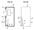
- Figs. 2A and 2B are a side sectional view and a side view showing the configuration of the speaker system according to this embodiment.
- a speaker 10 having a voice coil, a magnet, etc. is mounted in a front surface of a speaker enclosure 20.
- the speaker enclosure 20 is a rectangular parallelepiped closed type enclosure which has six surfaces each made of a plate-like member (such as wood, synthetic resin, metal or plywood thereof).
- a thin plate-like vibration plate 30 is attached to a baffle plate 20a in a front surface of the speaker enclosure 20.
- the vibration plate 30 is formed to have a size equal to the size of the front surface of the speaker enclosure 20 so that the front surface of the speaker enclosure 20 is entirely covered with the vibration plate 30.
- a speaker mount hole is provided so as to pierce both the vibration plate 30 and the baffle plate 20a.
- the speaker 10 is inserted in the speaker mount hole. In this case, a front frame of the speaker 10 is fixed to the vibration plate 30 and the baffle plate 20a by screws.
- the baffle plate 20a is formed so as to correspond to only an upper half of the front surface of the speaker enclosure 20.
- a bottom surface 20c of the speaker enclosure 20 is formed so as to be slightly shorter than an upper surface 20d of the speaker enclosure 20.
- the front side of the bottom surface 20c comes up forward from below to thereby form a front end portion 20e extending upward.
- a front lower portion of each side surface 20f of the speaker enclosure 20 is inclined in a range of from a lower end of the baffle plate 20a to the front end portion 20e of the bottom surface 20c to thereby form an inclined portion 20g.
- a space surrounded by the lower end of the baffle plate 20a, the inclined portion 20g and an upper edge of the front end portion 20e is provided as an opening portion 20b.
- the upper portion of the vibration plate 30 is fixed to the baffle plate 20a whereas the lower portion of the vibration plate 30 is opposed to the opening portion 20b.
- the lower portion of the vibration plate 30 serves as a free end of a cantilever so that the lower portion of the vibration plate 30 can vibrate freely due to elasticity of the vibration plate 30.
- vibration region 30a the lower portion of the vibration plate 30 will be referred to as "vibration region 30a".
- the vibration plate 30 is made of a member having both acoustically sufficient strength and elasticity.
- acoustically sufficient strength means that the member is airproof and sufficiently higher in density than air so that the member has sufficient strength and elasticity to generate acoustic wave when the member vibrates.
- the vibration plate 30 has such a property that a certain degree of acoustic wave can be blocked by the vibration plate 30 itself.
- the degree of "elasticity” is such a degree that the vibration plate 30 can be kept substantially horizontal with its own weight supported when the vibration plate 30 is placed horizontally while one side of the vibration plate 30 is fixed.
- the vibration plate 30 is made of a plate-like member such as thin wood, thin synthetic resin, metal or plywood thereof.
- the reference numeral 40 designates an edge which is provided between an outer circumferential flange of the vibration region 30a of the vibration plate 30 and a rim portion of the opening portion 20b for keeping the speaker enclosure 20 airtight.
- the edge 40 protrudes toward the inner space of the speaker enclosure 20 between a side edge of the vibration region 30a and the inclined portion 20g so that a bent portion (hereinafter referred to as "bent 40a”) of the edge 40 extends vertically.
- the edge 40 protrudes toward the inner space of the speaker enclosure 20 between a lower end edge of the vibration region 30a and the front end portion 20e so that a bent portion (hereinafter referred to as "bent 40b”) of the edge 40 extends horizontally.
- Fig. 3 is a front view of the speaker enclosure 20 in a state where the vibration plate 30 is removed.
- the hatched portion in Fig. 3 shows the edge 40. Portions of the edge 40 protruding toward the inner space of the speaker enclosure 20 are bents 40a and 40b.
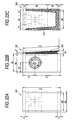
- Fig. 4 is a bottom view of the speaker enclosure 20.
- Fig. 5 is a sectional view taken along the line A-A in Fig. 3.
- the outer circumferential flange portion of the edge 40 shown in Fig. 3 is bonded to an outer circumferential edge portion of the vibration region 30a of the vibration plate 30 to thereby keep the speaker enclosure 20 airtight.
- the bents 40a and 40b of the edge 40 can be bent freely, so that the vibration region 30a can vibrate freely without disturbance.
- a speaker terminal connected to the voice coil of the speaker 10 is provided in the rear surface of the speaker enclosure 20.
- the air spring and the elasticity (spring characteristic) of the vibration plate 30 work equivalently as if two springs were connected in parallel to each other.
- the resonance frequency of the vibration plate 30 as the resonance frequency of the speaker system is however substantially determined on the basis of the compliance of the air and the equivalent mass of the vibration plate 30 because the compliance of the air spring is smaller than the compliance of the spring function of the vibration plate 30.
- the resonance frequency determined thus can be easily set to a desired value in a bass region.
- a resonance frequency of 50 Hz can be obtained as the resonance frequency of the vibration plate if the mass of the vibration plate 30 is 135 grams.
- Fig. 6A shows frequency characteristic of the speaker 10 in the aforementioned specific example.
- Fig. 6B shows frequency characteristic of the vibration plate 30 in the aforementioned specific example.
- bass with emphasized frequencies near 50 Hz can be output intensively when the aforementioned numerical values are set in this embodiment.
- the function of a passive radiator such as a drawn cone can be obtained by use of flexural vibration of the vibration plate 30.
- the vibration region 30a reproduces bass in a primary vibration mode in which the vibration region 30a vibrates while bent as a whole like a "paper fan". This is because the vibration plate 30 is entirely driven by air though secondary and tertiary vibration modes and higher-order vibration modes are present in the vibration plate 30, so that the level of occurrence of the primary vibration mode becomes the highest whereas the levels of occurrence of other vibration modes become low. To suppress the higher-order modes more sufficiently, adjustment can be made by the material and thickness of the vibration plate 30 or lamination of materials.
- the vibration plate 30 can be kept horizontal by itself even in the case where the vibration plate 30 is placed horizontally because the vibration plate 30 has elasticity enough to support its own weight.
- elasticity of the vibration plate 30 itself serves as compliance of free resonance, the loss at vibration is sufficiently small because the inner loss of the vibration plate 30 having elasticity is far smaller than the inner loss of the edge 40 having elasticity of the same degree.
- the material of the edge 40 can be made softer than the material of the edge used in a drawn cone in the background art. Moreover, the edge 40 need not have mechanical strength. In the background-art passive radiator such as a drawn cone, the edge has the two functions of supporting the vibration plate and keeping the speaker enclosure airtight because the passive radiator needs a structure in which the rigid vibration plate is supported by the edge. In this embodiment, however, the edge 40 need not have any support function because the function of supporting the vibration plate 30 is given to the vibration plate 30 itself. For this reason, a soft material which could not be used in the background art can be used as the material of the edge 40 as long as the speaker enclosure 20 can be kept airtight.
- the resonance frequency of the vibration plate 30 can be reduced when the mass of the vibration plate 30 is increased. That is, the resonance frequency can be adjusted in accordance with the size, material, etc. of the vibration plate 30. The resonance frequency can be also easily adjusted when a certain member is stuck to the vibration plate 30.
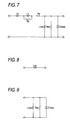
- Fig. 7 shows an electrically equivalent circuit of the speaker.
- the reference symbols are as follows.
- Fig. 8 shows an equivalent circuit of the speaker enclosure.
- the reference symbol Lve designates equivalent volume inductance.
- Fig. 9 shows an equivalent circuit of the background-art passive radiator such as a drawn cone or a hinge-fixed vibration plate. As shown in Fig. 9, the equivalent circuit has a circuit configuration in which the factor of the voice coil is removed from the speaker. Mass Cmep is supported by compliance Lcep and damping resistance Rep of the edge.
- the reference symbols are as follows.
- the low-frequency resonance frequency of the system is substantially equal to the resonance frequency of Cmep and Lve.
- Cmep the resonance frequency of Cmep and Lve.
- the edge needs to be durable and strong.
- a soft material such as rubber or urethane is used as the material of the edge. It is therefore necessary to thicken the edge in order to increase the strength. Thickening the edge, however, means increasing damping force as well as reducing the equivalent compliance Lcep (i.e. reducing the resistance value Rep in terms of expression in the electrically equivalent circuit). For this reason, the loss of the passive radiator becomes so large that bass reproducibility is reduced.
- Fig. 11 shows an equivalent circuit of the vibration plate according to the invention. Because a side of the vibration plate is entirely fixed, the vibration plate itself has compliance Lceb to support its own weight. Because the vibration plate is made of an elastic substance, the resistance component such as the edge material can be ignored. Because the edge need not support the weight of the vibration plate, a thin material can be used as the material of the edge. Accordingly, compliance Lcex can be increased to a very large value, so that the loss can be reduced to a very small value necessarily (i.e. damping resistance Rex can be increased to a large value in terms of expression in the electrically equivalent circuit).
- the reference symbols are as follows.
- Fig. 13 is a perspective view showing external appearance of the second embodiment of the invention.
- a speaker 10 is mounted in an upper portion of a baffle plate 50a in a front surface of a rectangular parallelepiped speaker enclosure 50.
- An opening portion 60 cut away as a narrow and long U-shaped portion is provided in a range of from a center portion of the baffle plate 50a to a lower portion of the baffle plate 50a.
- the inner portion of the U-shaped portion serves as a vibration plate 51. That is, an upper portion of the vibration plate 51 is integrated with the baffle plate 50a while the other portion of the vibration plate 51 is separated from the baffle plate 50a by the U-shaped opening portion 60. Accordingly, the vibration plate 51 can vibrate freely in a state where the upper end of the vibration plate 51 is fixed.
- Figs. 14A and 14B are a side sectional view and a cross-sectional view showing this embodiment.
- the opening portion 60 is covered with an edge 70 shaped like an arch in sectional view, from the inside of the speaker enclosure 50.
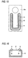
- Fig. 15 is a rear view of the baffle plate 50a.
- the edge 70 covers the U-shaped opening portion 60 along the shape thereof.
- the vibration plate 51 itself has a support function because a side of the vibration plate 51 is provided as a fixed end connected to the baffle plate 50a. For this reason, the edge 70 need not support the weight of the vibration plate 51 as long as the edge 70 has the function of keeping the speaker enclosure airtight. Accordingly, a soft material can be used as the material of the edge 70. As a result, a situation that vibration of the vibration plate 51 is not prevented, that is, a situation that the vibration plate 51 can move easily, can be formed.
- the operation of this embodiment is the same as that of the first embodiment in that a frequency band (bass band) near the resonance frequency of the vibration plate 51 is boosted.
- Fig. 16 is a cross-sectional view corresponding to Fig. 14B.
- the second embodiment has been described upon the case where the opening portion is provided in a speaker-provision surface of the speaker enclosure to thereby form the vibration plate, the position where the vibration plate is formed (i.e. the opening portion is provided) is not limited thereto. Any position may be used as long as the position is in a wall surface of the speaker enclosure.
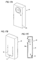
- Figs. 17A to 17C are views showing an example of the position where the vibration plate is formed.
- Fig. 17A is a perspective view showing external appearance of a speaker system.
- Fig. 17B is a perspective view of the modified example from the rear.
- Fig. 17C is a side sectional view.
- an opening portion 60 is provided in a surface opposite to a baffle plate 50a, that is, in the rear surface of a speaker enclosure 50.
Landscapes
- Health & Medical Sciences (AREA)
- Otolaryngology (AREA)
- Physics & Mathematics (AREA)
- Engineering & Computer Science (AREA)
- Acoustics & Sound (AREA)
- Signal Processing (AREA)
- Details Of Audible-Bandwidth Transducers (AREA)
- Obtaining Desirable Characteristics In Audible-Bandwidth Transducers (AREA)
Applications Claiming Priority (1)
| Application Number | Priority Date | Filing Date | Title |
|---|---|---|---|
| JP2005193071A JP4059259B2 (ja) | 2005-06-30 | 2005-06-30 | スピーカシステムおよびスピーカエンクロージャー |
Publications (3)
| Publication Number | Publication Date |
|---|---|
| EP1740013A2 true EP1740013A2 (fr) | 2007-01-03 |
| EP1740013A3 EP1740013A3 (fr) | 2009-11-11 |
| EP1740013B1 EP1740013B1 (fr) | 2015-09-23 |
Family
ID=37027025
Family Applications (1)
| Application Number | Title | Priority Date | Filing Date |
|---|---|---|---|
| EP06013167.9A Active EP1740013B1 (fr) | 2005-06-30 | 2006-06-26 | Système de haut-parleur et enceinte de haut-parleur |
Country Status (5)
| Country | Link |
|---|---|
| US (1) | US7481295B2 (fr) |
| EP (1) | EP1740013B1 (fr) |
| JP (1) | JP4059259B2 (fr) |
| CN (1) | CN1893732B (fr) |
| TW (1) | TWI325727B (fr) |
Cited By (2)
| Publication number | Priority date | Publication date | Assignee | Title |
|---|---|---|---|---|
| CN105430579A (zh) * | 2016-01-01 | 2016-03-23 | 苏州井利电子股份有限公司 | 一种用于扬声器的耐水性纸盆 |
| CN105430578A (zh) * | 2016-01-01 | 2016-03-23 | 苏州井利电子股份有限公司 | 一种用于扬声器的纸盆 |
Families Citing this family (28)
| Publication number | Priority date | Publication date | Assignee | Title |
|---|---|---|---|---|
| US5802191A (en) * | 1995-01-06 | 1998-09-01 | Guenther; Godehard A. | Loudspeakers, systems, and components thereof |
| US8588457B2 (en) * | 1999-08-13 | 2013-11-19 | Dr. G Licensing, Llc | Low cost motor design for rare-earth-magnet loudspeakers |
| WO2006029378A2 (fr) | 2004-09-09 | 2006-03-16 | Guenther Godehard A | Haut-parleurs et systemes |
| JP4192934B2 (ja) * | 2005-10-07 | 2008-12-10 | ヤマハ株式会社 | スピーカシステム |
| TW200846838A (en) * | 2007-01-26 | 2008-12-01 | Nikon Corp | Support structure and exposure apparatus |
| US8189840B2 (en) | 2007-05-23 | 2012-05-29 | Soundmatters International, Inc. | Loudspeaker and electronic devices incorporating same |
| KR100956552B1 (ko) * | 2008-02-27 | 2010-05-07 | 박승민 | 비주얼 스피커의 oled 및 콘페이퍼 유동 제어장치 |
| KR20100019642A (ko) * | 2008-08-11 | 2010-02-19 | 삼성전자주식회사 | 스피커장치 및 이를 구비하는 영상표시장치 |
| US8189851B2 (en) | 2009-03-06 | 2012-05-29 | Emo Labs, Inc. | Optically clear diaphragm for an acoustic transducer and method for making same |
| US20110274283A1 (en) * | 2009-07-22 | 2011-11-10 | Lewis Athanas | Open Air Noise Cancellation |
| US8104569B2 (en) * | 2009-07-29 | 2012-01-31 | Klein Daniel B | Speaker cabinet system |
| US8520876B2 (en) | 2010-06-25 | 2013-08-27 | Tzu-Chung Chang | Assembly structure for speaker system |
| JP5906709B2 (ja) * | 2011-12-13 | 2016-04-20 | ヤマハ株式会社 | スピーカ |
| WO2014143927A2 (fr) | 2013-03-15 | 2014-09-18 | Emo Labs, Inc. | Transducteurs acoustiques |
| USD721674S1 (en) * | 2013-05-20 | 2015-01-27 | Gramovox, LLC | Speaker base |
| USD733678S1 (en) | 2013-12-27 | 2015-07-07 | Emo Labs, Inc. | Audio speaker |
| USD741835S1 (en) | 2013-12-27 | 2015-10-27 | Emo Labs, Inc. | Speaker |
| USD748072S1 (en) | 2014-03-14 | 2016-01-26 | Emo Labs, Inc. | Sound bar audio speaker |
| US9525932B2 (en) * | 2015-01-26 | 2016-12-20 | Bose Corporation | Acoustic device having active drivers mounted to a passive radiator diaphragm |
| US10063961B2 (en) * | 2015-09-08 | 2018-08-28 | Charles M Paris | Chambered enclosure for use with audio loudspeakers |
| CN105554641A (zh) * | 2016-01-01 | 2016-05-04 | 苏州井利电子股份有限公司 | 一种用于扬声器的耐疲劳纸盆 |
| CN105530574A (zh) * | 2016-01-01 | 2016-04-27 | 苏州井利电子股份有限公司 | 一种用于扬声器的高强度纸盆 |
| CN112653964B (zh) * | 2018-04-26 | 2022-06-28 | 深圳市韶音科技有限公司 | 一种耳机系统 |
| KR102007034B1 (ko) * | 2018-08-20 | 2019-08-02 | 최금정 | 증폭 확산 스피커 |
| TWI719639B (zh) * | 2019-09-17 | 2021-02-21 | 緯創資通股份有限公司 | 聲音擴散裝置與具有該聲音擴散裝置之揚聲器 |
| WO2021064896A1 (fr) * | 2019-10-02 | 2021-04-08 | 株式会社アクション・リサーチ | Dispositif de haut-parleur et procédé de fabrication d'un dispositif de haut-parleur |
| USD919597S1 (en) * | 2019-12-20 | 2021-05-18 | Yamaha Corporation | Speaker |
| CN117915234A (zh) * | 2023-12-18 | 2024-04-19 | 张永春 | 低音反射系统 |
Citations (4)
| Publication number | Priority date | Publication date | Assignee | Title |
|---|---|---|---|---|
| WO2000032010A2 (fr) | 1998-11-24 | 2000-06-02 | B & W Loudspeakers Limited | Emetteur auxiliaire de basses |
| EP1217998A2 (fr) | 1999-10-05 | 2002-07-03 | Grünenthal GmbH | Utilisation de (+)-tramadol, de o-demethyltramadol ou de (+)-o-demethyltramadol, de o-desmethyle-n-mono-desmethyl-tramadol ou de (+)o-desmethyl-n-mono-desmethyl-tramadol pour traiter l'incontinence urinaire |
| US20040188174A1 (en) | 1998-11-30 | 2004-09-30 | Sahyoun Joseph Yaacoub | Audio speaker with wobble free voice coil movement |
| WO2005029917A1 (fr) | 2003-09-18 | 2005-03-31 | Norton John M | Enceinte acoustique de haut-parleur audio |
Family Cites Families (29)
| Publication number | Priority date | Publication date | Assignee | Title |
|---|---|---|---|---|
| US1839714A (en) * | 1930-09-05 | 1932-01-05 | Tauscher | Amplifier for sound reproducing devices |
| US2713396A (en) * | 1950-05-24 | 1955-07-19 | Ernest A Tavares | Novel, small, extended low frequency response, loudspeaker enclosure |
| US2834423A (en) * | 1954-09-01 | 1958-05-13 | Robert L Bradford | High fidelity loud speaker enclosure |
| US3233695A (en) * | 1964-07-10 | 1966-02-08 | Budsen Corp | Speaker enclosure |
| US3319737A (en) * | 1966-06-17 | 1967-05-16 | Barthel Lucien | Acoustical enclosures |
| JPS53131325A (en) | 1978-01-31 | 1978-11-16 | Nippon Denso Co Ltd | Distrubution type fuel injection pump |
| US4618025A (en) * | 1980-09-15 | 1986-10-21 | Sherman Dan R | Acoustical ducting for speakers and enclosures |
| US4392548A (en) * | 1980-11-13 | 1983-07-12 | Engineering Development Company | Speaker enclosure and method of producing same |
| US4598789A (en) * | 1982-04-19 | 1986-07-08 | Temporal Dynamics Research, Inc. | Sound reproducing |
| US4714133A (en) * | 1985-06-14 | 1987-12-22 | Skaggs Jr John E | Method and apparatus for augmentation of sound by enhanced resonance |
| US5150417A (en) * | 1991-02-25 | 1992-09-22 | Socon Ab | Bass reflex type speaker system |
| JPH04309096A (ja) | 1991-04-05 | 1992-10-30 | Sony Corp | スピーカシステム |
| US5204501A (en) * | 1992-02-20 | 1993-04-20 | Tsao Ye Ming | Synchronous common polar resonant wall type speaker cabinet |
| US5216210A (en) * | 1992-02-27 | 1993-06-01 | Kammer Brent T | Loudspeaker system with passive sound reflective intensifier |
| US5749433A (en) * | 1996-02-13 | 1998-05-12 | Jackson; Michael | Massline loudspeaker enclosure |
| US5731552A (en) * | 1996-05-21 | 1998-03-24 | Tsao; Ye-Ming | Speaker system with sound absorbing diaphragm |
| DE60226098T2 (de) * | 2001-06-28 | 2009-06-18 | Panasonic Corp., Kadoma | Lautsprechersystem, Mobilendgerät und elektronische Vorrichtung |
| US7158648B2 (en) * | 2002-07-30 | 2007-01-02 | Harman International Industries, Incorporated | Loudspeaker system with extended bass response |
| US7133533B2 (en) * | 2003-07-21 | 2006-11-07 | Bose Corporation | Passive acoustic radiating |
| CN101023703B (zh) * | 2004-09-13 | 2011-09-07 | 松下电器产业株式会社 | 扬声器系统 |
| JP4192934B2 (ja) * | 2005-10-07 | 2008-12-10 | ヤマハ株式会社 | スピーカシステム |
| JP4600241B2 (ja) * | 2005-10-11 | 2010-12-15 | ヤマハ株式会社 | スピーカシステムおよびスピーカエンクロージャー |
| JP4059263B2 (ja) * | 2005-10-11 | 2008-03-12 | ヤマハ株式会社 | スピーカシステムおよびスピーカエンクロージャー |
| JP4148253B2 (ja) * | 2005-10-12 | 2008-09-10 | ヤマハ株式会社 | スピーカシステムおよびスピーカエンクロージャー |
| JP4821274B2 (ja) * | 2005-11-04 | 2011-11-24 | ヤマハ株式会社 | スピーカシステムおよびスピーカエンクロージャー |
| JP4910372B2 (ja) * | 2005-11-18 | 2012-04-04 | ヤマハ株式会社 | スピーカシステムおよびスピーカエンクロージャー |
| JP4821288B2 (ja) * | 2005-11-29 | 2011-11-24 | ヤマハ株式会社 | スピーカシステムおよびスピーカエンクロージャー |
| JP4059272B2 (ja) * | 2006-01-18 | 2008-03-12 | ヤマハ株式会社 | スピーカシステムおよびスピーカエンクロージャー |
| JP4277876B2 (ja) * | 2006-06-16 | 2009-06-10 | ヤマハ株式会社 | スピーカシステムおよびスピーカエンクロージャー |
-
2005
- 2005-06-30 JP JP2005193071A patent/JP4059259B2/ja not_active Expired - Lifetime
-
2006
- 2006-06-21 US US11/472,883 patent/US7481295B2/en active Active
- 2006-06-22 TW TW095122396A patent/TWI325727B/zh not_active IP Right Cessation
- 2006-06-26 EP EP06013167.9A patent/EP1740013B1/fr active Active
- 2006-06-30 CN CN2006100907777A patent/CN1893732B/zh active Active
Patent Citations (4)
| Publication number | Priority date | Publication date | Assignee | Title |
|---|---|---|---|---|
| WO2000032010A2 (fr) | 1998-11-24 | 2000-06-02 | B & W Loudspeakers Limited | Emetteur auxiliaire de basses |
| US20040188174A1 (en) | 1998-11-30 | 2004-09-30 | Sahyoun Joseph Yaacoub | Audio speaker with wobble free voice coil movement |
| EP1217998A2 (fr) | 1999-10-05 | 2002-07-03 | Grünenthal GmbH | Utilisation de (+)-tramadol, de o-demethyltramadol ou de (+)-o-demethyltramadol, de o-desmethyle-n-mono-desmethyl-tramadol ou de (+)o-desmethyl-n-mono-desmethyl-tramadol pour traiter l'incontinence urinaire |
| WO2005029917A1 (fr) | 2003-09-18 | 2005-03-31 | Norton John M | Enceinte acoustique de haut-parleur audio |
Cited By (2)
| Publication number | Priority date | Publication date | Assignee | Title |
|---|---|---|---|---|
| CN105430579A (zh) * | 2016-01-01 | 2016-03-23 | 苏州井利电子股份有限公司 | 一种用于扬声器的耐水性纸盆 |
| CN105430578A (zh) * | 2016-01-01 | 2016-03-23 | 苏州井利电子股份有限公司 | 一种用于扬声器的纸盆 |
Also Published As
| Publication number | Publication date |
|---|---|
| CN1893732A (zh) | 2007-01-10 |
| CN1893732B (zh) | 2010-08-11 |
| JP4059259B2 (ja) | 2008-03-12 |
| EP1740013B1 (fr) | 2015-09-23 |
| EP1740013A3 (fr) | 2009-11-11 |
| US7481295B2 (en) | 2009-01-27 |
| US20070000720A1 (en) | 2007-01-04 |
| TWI325727B (en) | 2010-06-01 |
| TW200727720A (en) | 2007-07-16 |
| JP2007013730A (ja) | 2007-01-18 |
Similar Documents
| Publication | Publication Date | Title |
|---|---|---|
| US7481295B2 (en) | Speaker system and speaker enclosure | |
| EP3637797B1 (fr) | Dispositif de production de son | |
| CA1322042C (fr) | Haut-parleur | |
| JP4192934B2 (ja) | スピーカシステム | |
| EP1487235A2 (fr) | Dispositif de haut-parleur | |
| US20060239488A1 (en) | Acoustic receiver having improved mechanical suspension | |
| JP4277876B2 (ja) | スピーカシステムおよびスピーカエンクロージャー | |
| JPH1153056A (ja) | 音道付きスピーカ・キャビネットを備えたポータブル・コンピュータ・システム | |
| US20110176701A1 (en) | Autoaugmented Speaker Port | |
| CN101444109B (zh) | 摇摆幅度减小了的扬声器 | |
| US6445803B1 (en) | Speaker | |
| JP4821274B2 (ja) | スピーカシステムおよびスピーカエンクロージャー | |
| KR100676421B1 (ko) | 일채널 투웨이 스피커 | |
| JP4059272B2 (ja) | スピーカシステムおよびスピーカエンクロージャー | |
| JP4910372B2 (ja) | スピーカシステムおよびスピーカエンクロージャー | |
| JP4600241B2 (ja) | スピーカシステムおよびスピーカエンクロージャー | |
| US7515724B2 (en) | Loudspeaker driver | |
| CN109982222A (zh) | 一种微型受话器 | |
| JP4821288B2 (ja) | スピーカシステムおよびスピーカエンクロージャー | |
| JP4600242B2 (ja) | スピーカシステムおよびスピーカエンクロージャー | |
| JP4148253B2 (ja) | スピーカシステムおよびスピーカエンクロージャー | |
| JP4059263B2 (ja) | スピーカシステムおよびスピーカエンクロージャー | |
| GB2387987A (en) | Louspeaker with integral secondary diaphragm or which fits onto existing speaker cone | |
| JPH0833082A (ja) | スピーカシステム | |
| CN116782080A (zh) | 高音增强型无源辐射器及无源辐射器音箱 |
Legal Events
| Date | Code | Title | Description |
|---|---|---|---|
| PUAI | Public reference made under article 153(3) epc to a published international application that has entered the european phase |
Free format text: ORIGINAL CODE: 0009012 |
|
| AK | Designated contracting states |
Kind code of ref document: A2 Designated state(s): AT BE BG CH CY CZ DE DK EE ES FI FR GB GR HU IE IS IT LI LT LU LV MC NL PL PT RO SE SI SK TR |
|
| AX | Request for extension of the european patent |
Extension state: AL BA HR MK YU |
|
| RAP1 | Party data changed (applicant data changed or rights of an application transferred) |
Owner name: YAMAHA CORPORATION |
|
| PUAL | Search report despatched |
Free format text: ORIGINAL CODE: 0009013 |
|
| AK | Designated contracting states |
Kind code of ref document: A3 Designated state(s): AT BE BG CH CY CZ DE DK EE ES FI FR GB GR HU IE IS IT LI LT LU LV MC NL PL PT RO SE SI SK TR |
|
| AX | Request for extension of the european patent |
Extension state: AL BA HR MK RS |
|
| 17P | Request for examination filed |
Effective date: 20100511 |
|
| 17Q | First examination report despatched |
Effective date: 20100608 |
|
| AKX | Designation fees paid |
Designated state(s): DE FR GB |
|
| GRAP | Despatch of communication of intention to grant a patent |
Free format text: ORIGINAL CODE: EPIDOSNIGR1 |
|
| INTG | Intention to grant announced |
Effective date: 20150331 |
|
| GRAS | Grant fee paid |
Free format text: ORIGINAL CODE: EPIDOSNIGR3 |
|
| GRAA | (expected) grant |
Free format text: ORIGINAL CODE: 0009210 |
|
| AK | Designated contracting states |
Kind code of ref document: B1 Designated state(s): DE FR GB |
|
| REG | Reference to a national code |
Ref country code: GB Ref legal event code: FG4D |
|
| REG | Reference to a national code |
Ref country code: DE Ref legal event code: R096 Ref document number: 602006046723 Country of ref document: DE |
|
| REG | Reference to a national code |
Ref country code: FR Ref legal event code: PLFP Year of fee payment: 11 |
|
| REG | Reference to a national code |
Ref country code: DE Ref legal event code: R097 Ref document number: 602006046723 Country of ref document: DE |
|
| PLBE | No opposition filed within time limit |
Free format text: ORIGINAL CODE: 0009261 |
|
| STAA | Information on the status of an ep patent application or granted ep patent |
Free format text: STATUS: NO OPPOSITION FILED WITHIN TIME LIMIT |
|
| 26N | No opposition filed |
Effective date: 20160624 |
|
| REG | Reference to a national code |
Ref country code: FR Ref legal event code: PLFP Year of fee payment: 12 |
|
| REG | Reference to a national code |
Ref country code: FR Ref legal event code: PLFP Year of fee payment: 13 |
|
| PGFP | Annual fee paid to national office [announced via postgrant information from national office to epo] |
Ref country code: GB Payment date: 20220622 Year of fee payment: 17 |
|
| PGFP | Annual fee paid to national office [announced via postgrant information from national office to epo] |
Ref country code: FR Payment date: 20220628 Year of fee payment: 17 |
|
| GBPC | Gb: european patent ceased through non-payment of renewal fee |
Effective date: 20230626 |
|
| PG25 | Lapsed in a contracting state [announced via postgrant information from national office to epo] |
Ref country code: GB Free format text: LAPSE BECAUSE OF NON-PAYMENT OF DUE FEES Effective date: 20230626 |
|
| PG25 | Lapsed in a contracting state [announced via postgrant information from national office to epo] |
Ref country code: FR Free format text: LAPSE BECAUSE OF NON-PAYMENT OF DUE FEES Effective date: 20230630 |
|
| PGFP | Annual fee paid to national office [announced via postgrant information from national office to epo] |
Ref country code: DE Payment date: 20250618 Year of fee payment: 20 |