EP1741497A2 - Procédé et dispositif pour produire sans enlèvement de matière une encoche dans une pièce et pièce avec une telle encoche - Google Patents
Procédé et dispositif pour produire sans enlèvement de matière une encoche dans une pièce et pièce avec une telle encoche Download PDFInfo
- Publication number
- EP1741497A2 EP1741497A2 EP06012029A EP06012029A EP1741497A2 EP 1741497 A2 EP1741497 A2 EP 1741497A2 EP 06012029 A EP06012029 A EP 06012029A EP 06012029 A EP06012029 A EP 06012029A EP 1741497 A2 EP1741497 A2 EP 1741497A2
- Authority
- EP
- European Patent Office
- Prior art keywords
- notch
- workpiece
- tool
- die
- wall
- Prior art date
- Legal status (The legal status is an assumption and is not a legal conclusion. Google has not performed a legal analysis and makes no representation as to the accuracy of the status listed.)
- Granted
Links
- 238000000034 method Methods 0.000 title claims description 30
- 238000005520 cutting process Methods 0.000 title description 10
- 230000007704 transition Effects 0.000 claims abstract description 9
- 238000004049 embossing Methods 0.000 claims description 15
- 238000004519 manufacturing process Methods 0.000 claims description 3
- 239000002184 metal Substances 0.000 claims description 3
- 239000000463 material Substances 0.000 description 34
- 238000005096 rolling process Methods 0.000 description 8
- 238000003754 machining Methods 0.000 description 4
- 238000013461 design Methods 0.000 description 3
- 238000010008 shearing Methods 0.000 description 3
- 230000015572 biosynthetic process Effects 0.000 description 2
- 238000003825 pressing Methods 0.000 description 2
- 238000007493 shaping process Methods 0.000 description 2
- 229910000760 Hardened steel Inorganic materials 0.000 description 1
- 238000010276 construction Methods 0.000 description 1
- 230000000694 effects Effects 0.000 description 1
- 238000003780 insertion Methods 0.000 description 1
- 230000037431 insertion Effects 0.000 description 1
- 239000011159 matrix material Substances 0.000 description 1
- 238000000465 moulding Methods 0.000 description 1
- 230000000149 penetrating effect Effects 0.000 description 1
- 238000012545 processing Methods 0.000 description 1
- 238000012360 testing method Methods 0.000 description 1
Images

Classifications
-
- B—PERFORMING OPERATIONS; TRANSPORTING
- B21—MECHANICAL METAL-WORKING WITHOUT ESSENTIALLY REMOVING MATERIAL; PUNCHING METAL
- B21D—WORKING OR PROCESSING OF SHEET METAL OR METAL TUBES, RODS OR PROFILES WITHOUT ESSENTIALLY REMOVING MATERIAL; PUNCHING METAL
- B21D17/00—Forming single grooves in sheet metal or tubular or hollow articles
- B21D17/02—Forming single grooves in sheet metal or tubular or hollow articles by pressing
- B21D17/025—Forming single grooves in sheet metal or tubular or hollow articles by pressing by pressing tubes axially
Definitions
- the invention relates to a workpiece with a non-machined notch and a tool for non-cutting introduction of a notch in a workpiece and a method for producing a non-machined notch.
- the workpiece according to the invention has an upper side and a lower side, as well as a non-machined notch.
- This notch has side faces and one Kerbground on; the notch extends from the top to the bottom of the tool. Unlike the prior art, the notch penetrates the entire thickness of the workpiece, extending from the top to the bottom of the workpiece.
- the depth of the notch can be greater than the thickness of the workpiece itself, ie the distance between the top and bottom of the workpiece.
- the depth of the notch may be at least 10%, preferably at least 20%, preferably at least 40%, more preferably at least 50% more than the thickness of the workpiece.
- the depth of the notch exceeding the thickness of the wall piece is referred to as a notch wall, which consequently adjoins the side surfaces and includes the notch base.
- the workpiece can be provided with notches whose cross-section is approximately U-shaped with respect to the upper side of the workpiece, ie in which the side surfaces are approximately at a right angle relative to the upper side of the workpiece. Consequently, these are notches with a substantially flat, preferably flat notch base.
- the side surfaces of the notch may be disposed at an angle ⁇ greater than 70 °, preferably greater than 80 °, more preferably greater than 85 °, relative to the top of the workpiece prior to notching. It is thus possible according to the invention to arrange the notch in a workpiece according to the invention with side faces arranged at least in sections approximately at right angles to the top side. Preferably, the approximately rectangular portions of the side surfaces extend to the top of the workpiece.
- Notches of approximately U-shaped cross section are often required in the construction of a workpiece when they are part of locking arrangements. It is obvious that the safety aspect plays a special role in locking arrangements, so that the notch geometry must be reliably maintained. Typical use case for such notches is the requirement of pipes of Headrests with deep, U-shaped notches to provide. Latches attached to the car seat engage in these notches so that the tight fit of the headrests is ensured.
- the above-described notches can be introduced into any type of workpiece, that is also in tubular workpieces.
- a workpiece is provided according to the invention, which is provided with a notch whose angle of incidence ⁇ is up to 10 °.
- the angle of incidence ⁇ is measured between the top of the workpiece before the notch (horizontal) and the top of the workpiece after notching.
- the incidence angle resulting from the notches is up to 5 °, more preferably up to 3 °, advantageously up to 1 °.
- a low angle of incidence often has to be met if the side surfaces of the notch are arranged approximately perpendicular to the top of the workpiece. By maintaining a low angle of incidence, the portion of the side surface approximately perpendicular to the top of the workpiece is maximized.
- the notch wall in the region in which the notch extends beyond the underside of the workpiece, in the region of the notch base, ie on the notch facing side of the notch wall, a different contour than the underside of the notch wall is created in this case with a tool that is composed of punch and die.
- the cross section of the notch on the "inside" is determined by the contour of the punch.
- the punch is molded according to the notch geometry requirements, such as the length and orientation requirements of the side surfaces, the contour of the notch root, or the angle of incidence.
- the die on the other hand, is generally not subject to such stringent mold requirements. It can be inventively formed freely depending on the material of the workpiece. It is inventively advantageous if the formed by the die bottom of the notch wall another Contour than the formed by the punch inside of the notch wall.
- the notch wall and possibly also the notch base in the area in which the notch extends beyond the underside of the workpiece has sections of different wall thickness.
- the wall thickness of the notch wall increases towards the side surfaces.
- a small wall thickness of the notch wall in the region between the side surfaces or at a distance from the side surfaces can be readily accepted for most embodiments.
- this design contributes to the fact that particularly deep notches can be marked.
- the invention further relates to a tool for embossing a notch.
- the tool has a punch, which penetrates into the workpiece and there forms the contour of the notch in the workpiece and a die, which coins the underside of the notch or the notch base, characterized in that the punch presses the workpiece against the die.
- the die in the region of the notch base on a web.
- the die has a recess in the region of the transition from the notch root to at least one side face of the notch.
- the formation of the die with web and recess is essential for the formation of particular deep U-shaped notches in workpieces. Notches extending across the entire thickness of the workpiece require shifting material of the workpiece beyond the bottom of the workpiece. The greater the angle ⁇ between the top and side surface of the notch, the sooner a non-cutting deformation of the workpiece causes a shearing or cutting of the material. It has surprisingly been found that this shearing or cutting can be very effectively countered if the recess in the die can accommodate sufficient material of the workpiece, which is displaced by the penetrating punch. This material preferably flows into the recess and is then available for forming the notch base.
- the invention provides to arrange a web in the die.
- the web is advantageously located in the middle of the notch base evenly spaced from the side surfaces.
- the bridge ensures that the notch base can be formed in a controlled manner by the stamp.
- the die is formed so that the recess in the region of the side surfaces of the notch extends beyond the web.
- the recess which is preferably arranged in the transition region between the notch root and side surfaces of the notch, thus extends according to this preferred embodiment not only beyond the depth of the notch or the notch root defined by the web.
- the die in this case is thus designed in cross-section approximately like a "W", in which the recess extends beyond the upper edge of the web out into the region of the side surfaces of the notch.
- the notch extends beyond the thickness of the workpiece, it creates space in the region of the side surfaces for the flow of the material of the workpiece.
- such a matrix is particularly suitable for producing deep, U-shaped notches.
- the depth of the recess has at least the thickness of the notch wall, shearing or cutting of the material of the workpiece will occur effectively avoided when forming the notch.
- the recess is provided with a rounded contour, this also helps to support the flow of the material of the workpiece. Above all, a rounding at the transition from the side surfaces into the recess and during the transition from the web into the recess, rounded transitions in the contour of the recess prove themselves.
- An advantageous embodiment of the tool according to the invention provides that punch and die cooperate in such a way that the notch base is arranged on or below the underside of the workpiece. In this way, particularly deep notches can be marked.
- punch and die are designed so that they are arranged at a predetermined pressure for introducing the stamp at a predetermined distance from each other and thereby dictate the wall thickness of the notch wall.
- the punch and die may have different contours, so that the distance between the punch and die sections is further or less.
- a two-part die is preferably used.
- a two-part die allows easy insertion and removal of the die inside the tube.
- the inventive advantage of the method according to claim 15 is particularly evident when notching pipes. Deep notches and notches of approximately U-shaped cross section are limited or expensive to produce with the previously known methods. This is because, as a rule, not enough material for the notch wall is available for such deep notches in pipes. The notch bottom is a weak point in the notches, which are deeper than the pipe wall. Particularly noticeable is this vulnerability z. B. when crash tests for vehicles, the headrest, which is held in such a notch, breaks off upon impact, because the tube in the notch base or in the notch wall has too little material to withstand the impact.
- displaced material is displaced in the direction of the notch base or the notch wall to be created. It is therefore promoted material exactly where it is necessary for reasons of strength and to create notches with extremely large notch depth.
- the method according to the invention is applied in such a way that the sections in the workpiece which are deformed by the first and the second tool overlap. This achieves as uniform a deformation as possible from the outset.
- Such an overlap of the distances of the tools is not absolutely necessary because-as will be explained below still other possibilities of chipless deformation in the inventive method can be included.
- Rollers or slides are preferably used according to the invention as tools.
- Roller tools and slides are known for non-cutting making notches per se. But they are always used in one direction and usually in a sequence of several tools in succession to produce a notch desired contour. In the context of the present invention, it is preferred to use as few tools as possible. Nevertheless, of course, especially if a lot of material is to be deformed or if a complex contour is to be created, different tools can be used, including tools that work in the same direction, but have a different contour.
- an angle of incidence ⁇ of less than 5 °, preferably of less than 3 °, particularly preferably of less than 1 °, can be maintained without problems, because when the tool is being rolled, the material is not drawn into the material Notch into it, as z. B. is typical for embossing.
- first and second tools deform one or more first and second tools the workpiece in several operations.
- a stationary arranged workpiece is processed.
- the first and second tools are movable, e.g. B. mounted on rails or on a carriage and move relative to the workpiece. They do not deform the workpiece in one operation but in several steps, for example, first a flat notch is made, which is then deepened in further operations until it has reached its final contour. In this way, notches with complex and / or precise contours can be made and notches can be made in which large amounts of material to be deformed.
- the workpiece to be scored is further deformed by stamping after the deformation by the first and the second tool in order to produce the notch.
- the embossing proves itself as a second processing step, in particular for producing the final notch depth, as advantageous. After the contour between top of the workpiece and side surfaces is created by a tangential or lateral force application of the first and second tools causes the radial force application in a third direction of the embossing stamp with little effort, the molding of the notch base.
- Fig. 1 shows a sectional view of the workpiece 1 together with the tool assembly consisting of punch 2 and die 3. To simplify the illustration only a partial section of the workpiece 1 has been shown. Also, the punch 2 is only partially shown at the top, not shown end of the punch 2 is a suitable device for exercising a matched to the material of the workpiece 1 pressure arranged, such as, for example, a pneumatically actuated plunger.
- the punch 2 and the die 3 are made of hardened steel.
- the die 3 has a web 4 in its longitudinal extension, laterally two recesses 5a, 5b are arranged.
- the web 4 serves as a stop to specify a controlled notch depth for the later notching process.
- the recesses 5a, 5b extend in the direction of movement of the punch 2 beyond the web 4 and have a round contour line, so that a cutting action during the notching process is avoided ,
- a force of approximately 60 kN is exerted on the workpiece 1 by punch 2 and die 3.
- the punch 2 displaces the material of the workpiece 1 in the direction of the die 2, as shown in FIG.
- the material of the workpiece 1 flows through the pressure exerted in the recesses 5a, 5b of the die 3, which are designed so that they can completely absorb the flowing material.
- the projecting web 4 and the pressing pressure of the punch 1 determine the notch depth.
- a layer of shifted material of defined thickness is formed between the punch 1 and the web 4, forming a notch base 6, as shown in FIG.
- the two recesses 5a and 5b are now completely filled by displaced material.
- the design of the recesses 5a, 5b must be chosen so that they are sufficient to receive the displaced material of the workpiece 1. However, depending on the application and the desired geometry of the notch, the recesses 5a, 5b can also be larger.
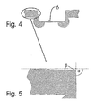
- FIG. 4 shows a workpiece notched according to the previously described method.
- the illustration clearly shows that the notch base 6 lies outside the original underside of the workpiece 1.
- the method allows extremely deep notches with the advantageous use of thin-walled workpieces, such as. Tubes.
- the shaping the recesses 5a, 5b of the die 3 produced at the notch walls sections of different wall thickness. Particularly in the areas of the transition from the region of the notch base 6 to the side walls, a thicker wall thickness with respect to the mechanical stability of the notch is advantageous.
- the recesses 5a and 5b of the die 3 can be adapted to the desired geometry of the notch.
- Fig. 5 shows the definition of the angle of incidence ⁇ and the angle ⁇ in an enlarged partial view of the surface of the workpiece of Fig. 4.
- the angle of incidence is measured between the original surface of the workpiece and the notch of the surface of the workpiece at the notch ,
- the angle ⁇ is measured between side wall of the notch and original surface.
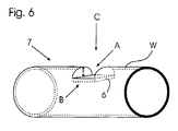
- FIG. 6 shows a perspective view of a notched pipe section 7.
- the pipe section 7 has a wall thickness W.
- the notch is made by a per se known rolling tool in a first working direction A tangential to the pipe section 7 to the apex of the pipe section, but not over the entire Length of the notch was guided. Subsequently, a second rolling tool in a second working direction B opposite to the working direction A, ie also tangent to the pipe section 7 to over the vertex of the pipe section, but not over the entire length of the notch out.
- the rolling tools known per se are not shown here for reasons of clarity.
- the first and second rolling tools are alternately guided five times in the pipe section.
- the notch depth is then the same depth as the wall thickness.
- the material from the pipe wall has been largely shifted to the notch bottom.
- the embossing die (not shown), which now radially deforms from the third working direction C, increases the notch depth T to the full extent, which is more than 50% above the wall thickness W.
Landscapes
- Engineering & Computer Science (AREA)
- Mechanical Engineering (AREA)
- Shaping Metal By Deep-Drawing, Or The Like (AREA)
- Turning (AREA)
- Mounting, Exchange, And Manufacturing Of Dies (AREA)
- Perforating, Stamping-Out Or Severing By Means Other Than Cutting (AREA)
- Forging (AREA)
- Punching Or Piercing (AREA)
- Container, Conveyance, Adherence, Positioning, Of Wafer (AREA)
Priority Applications (2)
| Application Number | Priority Date | Filing Date | Title |
|---|---|---|---|
| PL06012029T PL1741497T3 (pl) | 2005-06-14 | 2006-06-12 | Sposób i narzędzie do bezwiórowego wytwarzania przedmiotów obrabianych z karbem i przedmiot obrabiany z karbem |
| SI200630699T SI1741497T1 (sl) | 2005-06-14 | 2006-06-12 | Postopek in orodje za izdelavo obdelovanca z Ĺľlebom brez odrezovanja in obdelovanec z Ĺľlebom |
Applications Claiming Priority (1)
| Application Number | Priority Date | Filing Date | Title |
|---|---|---|---|
| DE102005027584A DE102005027584A1 (de) | 2005-06-14 | 2005-06-14 | Werkstück mit einer nicht-spanend erzeugten Kerbe |
Publications (4)
| Publication Number | Publication Date |
|---|---|
| EP1741497A2 true EP1741497A2 (fr) | 2007-01-10 |
| EP1741497A3 EP1741497A3 (fr) | 2007-02-28 |
| EP1741497B1 EP1741497B1 (fr) | 2010-03-31 |
| EP1741497B9 EP1741497B9 (fr) | 2010-09-01 |
Family
ID=37021062
Family Applications (1)
| Application Number | Title | Priority Date | Filing Date |
|---|---|---|---|
| EP06012029A Not-in-force EP1741497B9 (fr) | 2005-06-14 | 2006-06-12 | Procédé et dispositif pour produire sans enlèvement de matière une encoche dans une pièce et pièce avec une telle encoche |
Country Status (6)
| Country | Link |
|---|---|
| EP (1) | EP1741497B9 (fr) |
| AT (1) | ATE462508T1 (fr) |
| DE (2) | DE102005027584A1 (fr) |
| ES (1) | ES2343814T3 (fr) |
| PL (1) | PL1741497T3 (fr) |
| SI (1) | SI1741497T1 (fr) |
Cited By (2)
| Publication number | Priority date | Publication date | Assignee | Title |
|---|---|---|---|---|
| DE102010064068A1 (de) * | 2010-12-23 | 2012-06-28 | Volkswagen Ag | Tragelement, insbesondere Tragstange für eine Kopfstütze mit Kopfstützen-Rastkerben mit verringerter Kerbwirkung |
| DE102008047531C5 (de) * | 2008-09-16 | 2013-08-01 | Grammer Aktiengesellschaft | Halterohr für Ausstattungseinrichtungen von Fahrzeuginnenräumen sowie Verfahren und Vorrichtung zum Erzeugen einer Aussparung in einem Halterohr |
Families Citing this family (1)
| Publication number | Priority date | Publication date | Assignee | Title |
|---|---|---|---|---|
| DE102021113473A1 (de) * | 2021-05-25 | 2022-12-01 | Erni International Ag | Prägegesenk für ein Stanzwerkzeug |
Citations (1)
| Publication number | Priority date | Publication date | Assignee | Title |
|---|---|---|---|---|
| US20050016248A1 (en) | 2003-07-25 | 2005-01-27 | Inoac Corporation Co., Ltd. | Method of working recessed portion in headrest stay and press apparatus for working recessed portion in headrest stay |
Family Cites Families (3)
| Publication number | Priority date | Publication date | Assignee | Title |
|---|---|---|---|---|
| JPH04143021A (ja) * | 1990-10-03 | 1992-05-18 | Masanobu Nakamura | 管材表面の凹部成形方法 |
| FR2816857B1 (fr) * | 2000-11-20 | 2003-02-28 | Faurecia Sieges Automobile | Procede et dispositif de crantage d'un tube d'armature pour un siege de vehicule automobile, notamment un tube d'armature d'appuie-tete |
| FR2842752B1 (fr) * | 2002-07-29 | 2005-02-11 | Macsoft | Presse pour le crantage d'un tube comportant en combinaison un mandrin introduit a l'interieur du tube et une piece conformee selon le cran a realiser. |
-
2005
- 2005-06-14 DE DE102005027584A patent/DE102005027584A1/de not_active Withdrawn
-
2006
- 2006-06-12 PL PL06012029T patent/PL1741497T3/pl unknown
- 2006-06-12 AT AT06012029T patent/ATE462508T1/de active
- 2006-06-12 SI SI200630699T patent/SI1741497T1/sl unknown
- 2006-06-12 EP EP06012029A patent/EP1741497B9/fr not_active Not-in-force
- 2006-06-12 DE DE502006006553T patent/DE502006006553D1/de active Active
- 2006-06-12 ES ES06012029T patent/ES2343814T3/es active Active
Patent Citations (1)
| Publication number | Priority date | Publication date | Assignee | Title |
|---|---|---|---|---|
| US20050016248A1 (en) | 2003-07-25 | 2005-01-27 | Inoac Corporation Co., Ltd. | Method of working recessed portion in headrest stay and press apparatus for working recessed portion in headrest stay |
Cited By (3)
| Publication number | Priority date | Publication date | Assignee | Title |
|---|---|---|---|---|
| DE102008047531C5 (de) * | 2008-09-16 | 2013-08-01 | Grammer Aktiengesellschaft | Halterohr für Ausstattungseinrichtungen von Fahrzeuginnenräumen sowie Verfahren und Vorrichtung zum Erzeugen einer Aussparung in einem Halterohr |
| US9132470B2 (en) | 2008-09-16 | 2015-09-15 | Grammer Ag | Support tube for motor-vehicle accessory and method and apparatus for making a recess therein |
| DE102010064068A1 (de) * | 2010-12-23 | 2012-06-28 | Volkswagen Ag | Tragelement, insbesondere Tragstange für eine Kopfstütze mit Kopfstützen-Rastkerben mit verringerter Kerbwirkung |
Also Published As
| Publication number | Publication date |
|---|---|
| ATE462508T1 (de) | 2010-04-15 |
| EP1741497B1 (fr) | 2010-03-31 |
| PL1741497T3 (pl) | 2010-10-29 |
| ES2343814T3 (es) | 2010-08-10 |
| DE102005027584A1 (de) | 2006-12-28 |
| EP1741497B9 (fr) | 2010-09-01 |
| DE502006006553D1 (de) | 2010-05-12 |
| EP1741497A3 (fr) | 2007-02-28 |
| SI1741497T1 (sl) | 2010-08-31 |
Similar Documents
| Publication | Publication Date | Title |
|---|---|---|
| DE102008047531B3 (de) | Halterohr für Ausstattungseinrichtungen von Fahrzeuginnenräumen sowie Verfahren und Vorrichtung zum Erzeugen einer Aussparung in einem Halterohr | |
| EP1986801B1 (fr) | PROCEDE ET DISPOSITIF DE Formation D'UNE DECOUPE OU D'UNE PERFORATION DANS LA PAROI D'UN COMPOSANT FORME PAR UN PROCEDE DE FACONNAGE SOUS HAUTE PRESSION INTERIEURE | |
| DE19614656A1 (de) | Verfahren zum Erhöhen der Wandungsstärke bei Hohlprofilen | |
| WO2008135415A2 (fr) | Dispositif de fabrication de profilés | |
| DE102018124702B4 (de) | Dachreling für ein Kraftfahrzeug | |
| DE19647963C2 (de) | Verfahren und Vorrichtung zur Herstellung von Löchern am Umfang von Hohlprofilen | |
| EP2094415B1 (fr) | Crémaillère | |
| EP2344288A2 (fr) | Procédé et dispositif pour réaliser un filetage extérieur sans enlèvement de matière sur des pièces creuses en métal | |
| EP1815922B1 (fr) | Procédé et outil pour le découpage fin de pièces ayant des petits rayons de coin et une profondeur fortement reduite en un seule étape | |
| DE102008060700B4 (de) | Verfahren und Vorrichtung zum Herstellen eines Käfigs eines Wälzlagers, sowie Käfig eines Wälzlagers | |
| DE102005057424B4 (de) | Verfahren und Vorrichtung zum kernlosen Einformen von Hohlprofilen | |
| DE102013001919B4 (de) | Verfahren zur Erzeugung eines Durchgangslochs in einem metalischen Körper und Verwendung eines solchen Verfahrens | |
| EP1741497B1 (fr) | Procédé et dispositif pour produire sans enlèvement de matière une encoche dans une pièce et pièce avec une telle encoche | |
| DE60307484T2 (de) | Presse zur herstellung von rastnuten in rohren mit einem in dem rohr angeordneten dorn und einem der hergestellten nut entsprechenden teil | |
| EP2097187B1 (fr) | Pièce moulée et son procédé de production | |
| DE3911441C2 (de) | Verfahren zur Herstellung eines halbgeteilten Lagers | |
| DE3208867A1 (de) | Verfahren und vorrichtung zum biegen von langgestreckten teilen | |
| DE102005003933B4 (de) | Dorn zum Strangpressen von Gegenständen und Verfahren zur Herstellung eines Strangpressproduktes | |
| DE9411461U1 (de) | Vorrichtung zum Hochdruckformen von Felgenkränzen | |
| DE19706218C2 (de) | Verfahren zum Formen eines gebogenen Bauteils im Rahmen der Innenhochdruck-Umformtechnik und Vorrichtung für die Durchführung des Verfahrens | |
| EP1646461A1 (fr) | Procede et dispositif d'usinage de zones marginales de corps creux cylindres | |
| DE10062836A1 (de) | Verfahren zur Herstellung eines rohrförmigen Hohlkörpers | |
| DE10120880B4 (de) | Verfahren zur Herstellung von Tiefziehteilen | |
| DE4133340A1 (de) | Kondensatorbechergehaeuse mit sollberstbereich sowie verfahren und werkzeug zu seiner herstellung | |
| WO2022090135A1 (fr) | Outil de formage et procédé d'extrusion par impact de pièces métalliques |
Legal Events
| Date | Code | Title | Description |
|---|---|---|---|
| PUAI | Public reference made under article 153(3) epc to a published international application that has entered the european phase |
Free format text: ORIGINAL CODE: 0009012 |
|
| AK | Designated contracting states |
Kind code of ref document: A2 Designated state(s): AT BE BG CH CY CZ DE DK EE ES FI FR GB GR HU IE IS IT LI LT LU LV MC NL PL PT RO SE SI SK TR |
|
| AX | Request for extension of the european patent |
Extension state: AL BA HR MK YU |
|
| PUAL | Search report despatched |
Free format text: ORIGINAL CODE: 0009013 |
|
| AK | Designated contracting states |
Kind code of ref document: A3 Designated state(s): AT BE BG CH CY CZ DE DK EE ES FI FR GB GR HU IE IS IT LI LT LU LV MC NL PL PT RO SE SI SK TR |
|
| AX | Request for extension of the european patent |
Extension state: AL BA HR MK YU |
|
| RAP1 | Party data changed (applicant data changed or rights of an application transferred) |
Owner name: HUPERZ AUTOMOTIVE SYSTEMS GMBH & CO KG |
|
| 17P | Request for examination filed |
Effective date: 20070816 |
|
| 17Q | First examination report despatched |
Effective date: 20070925 |
|
| AKX | Designation fees paid |
Designated state(s): AT BE BG CH CY CZ DE DK EE ES FI FR GB GR HU IE IS IT LI LT LU LV MC NL PL PT RO SE SI SK TR |
|
| RAP1 | Party data changed (applicant data changed or rights of an application transferred) |
Owner name: PAMPUS AUTOMOTIVE GMBH & CO. KG |
|
| GRAP | Despatch of communication of intention to grant a patent |
Free format text: ORIGINAL CODE: EPIDOSNIGR1 |
|
| GRAS | Grant fee paid |
Free format text: ORIGINAL CODE: EPIDOSNIGR3 |
|
| GRAA | (expected) grant |
Free format text: ORIGINAL CODE: 0009210 |
|
| AK | Designated contracting states |
Kind code of ref document: B1 Designated state(s): AT BE BG CH CY CZ DE DK EE ES FI FR GB GR HU IE IS IT LI LT LU LV MC NL PL PT RO SE SI SK TR |
|
| REG | Reference to a national code |
Ref country code: GB Ref legal event code: FG4D Free format text: NOT ENGLISH Ref country code: CH Ref legal event code: EP |
|
| REG | Reference to a national code |
Ref country code: IE Ref legal event code: FG4D |
|
| REF | Corresponds to: |
Ref document number: 502006006553 Country of ref document: DE Date of ref document: 20100512 Kind code of ref document: P |
|
| REG | Reference to a national code |
Ref country code: NL Ref legal event code: VDEP Effective date: 20100331 |
|
| RAP2 | Party data changed (patent owner data changed or rights of a patent transferred) |
Owner name: THIEL & HOCHE GMBH & CO. KG |
|
| PG25 | Lapsed in a contracting state [announced via postgrant information from national office to epo] |
Ref country code: LT Free format text: LAPSE BECAUSE OF FAILURE TO SUBMIT A TRANSLATION OF THE DESCRIPTION OR TO PAY THE FEE WITHIN THE PRESCRIBED TIME-LIMIT Effective date: 20100331 |
|
| REG | Reference to a national code |
Ref country code: ES Ref legal event code: FG2A Ref document number: 2343814 Country of ref document: ES Kind code of ref document: T3 |
|
| LTIE | Lt: invalidation of european patent or patent extension |
Effective date: 20100331 |
|
| PG25 | Lapsed in a contracting state [announced via postgrant information from national office to epo] |
Ref country code: LV Free format text: LAPSE BECAUSE OF FAILURE TO SUBMIT A TRANSLATION OF THE DESCRIPTION OR TO PAY THE FEE WITHIN THE PRESCRIBED TIME-LIMIT Effective date: 20100331 Ref country code: FI Free format text: LAPSE BECAUSE OF FAILURE TO SUBMIT A TRANSLATION OF THE DESCRIPTION OR TO PAY THE FEE WITHIN THE PRESCRIBED TIME-LIMIT Effective date: 20100331 |
|
| REG | Reference to a national code |
Ref country code: FR Ref legal event code: TP |
|
| REG | Reference to a national code |
Ref country code: IE Ref legal event code: FD4D |
|
| PG25 | Lapsed in a contracting state [announced via postgrant information from national office to epo] |
Ref country code: NL Free format text: LAPSE BECAUSE OF FAILURE TO SUBMIT A TRANSLATION OF THE DESCRIPTION OR TO PAY THE FEE WITHIN THE PRESCRIBED TIME-LIMIT Effective date: 20100331 Ref country code: EE Free format text: LAPSE BECAUSE OF FAILURE TO SUBMIT A TRANSLATION OF THE DESCRIPTION OR TO PAY THE FEE WITHIN THE PRESCRIBED TIME-LIMIT Effective date: 20100331 Ref country code: CY Free format text: LAPSE BECAUSE OF FAILURE TO SUBMIT A TRANSLATION OF THE DESCRIPTION OR TO PAY THE FEE WITHIN THE PRESCRIBED TIME-LIMIT Effective date: 20100331 Ref country code: SE Free format text: LAPSE BECAUSE OF FAILURE TO SUBMIT A TRANSLATION OF THE DESCRIPTION OR TO PAY THE FEE WITHIN THE PRESCRIBED TIME-LIMIT Effective date: 20100331 |
|
| REG | Reference to a national code |
Ref country code: PL Ref legal event code: T3 |
|
| PG25 | Lapsed in a contracting state [announced via postgrant information from national office to epo] |
Ref country code: SK Free format text: LAPSE BECAUSE OF FAILURE TO SUBMIT A TRANSLATION OF THE DESCRIPTION OR TO PAY THE FEE WITHIN THE PRESCRIBED TIME-LIMIT Effective date: 20100331 Ref country code: IS Free format text: LAPSE BECAUSE OF FAILURE TO SUBMIT A TRANSLATION OF THE DESCRIPTION OR TO PAY THE FEE WITHIN THE PRESCRIBED TIME-LIMIT Effective date: 20100731 |
|
| BERE | Be: lapsed |
Owner name: PAMPUS AUTOMOTIVE G.M.B.H. & CO. KG Effective date: 20100630 |
|
| PG25 | Lapsed in a contracting state [announced via postgrant information from national office to epo] |
Ref country code: DK Free format text: LAPSE BECAUSE OF FAILURE TO SUBMIT A TRANSLATION OF THE DESCRIPTION OR TO PAY THE FEE WITHIN THE PRESCRIBED TIME-LIMIT Effective date: 20100331 Ref country code: MC Free format text: LAPSE BECAUSE OF NON-PAYMENT OF DUE FEES Effective date: 20100630 Ref country code: PT Free format text: LAPSE BECAUSE OF FAILURE TO SUBMIT A TRANSLATION OF THE DESCRIPTION OR TO PAY THE FEE WITHIN THE PRESCRIBED TIME-LIMIT Effective date: 20100802 Ref country code: IE Free format text: LAPSE BECAUSE OF FAILURE TO SUBMIT A TRANSLATION OF THE DESCRIPTION OR TO PAY THE FEE WITHIN THE PRESCRIBED TIME-LIMIT Effective date: 20100331 |
|
| REG | Reference to a national code |
Ref country code: CH Ref legal event code: PL |
|
| PLBE | No opposition filed within time limit |
Free format text: ORIGINAL CODE: 0009261 |
|
| STAA | Information on the status of an ep patent application or granted ep patent |
Free format text: STATUS: NO OPPOSITION FILED WITHIN TIME LIMIT |
|
| GBPC | Gb: european patent ceased through non-payment of renewal fee |
Effective date: 20100630 |
|
| 26N | No opposition filed |
Effective date: 20110104 |
|
| PG25 | Lapsed in a contracting state [announced via postgrant information from national office to epo] |
Ref country code: IT Free format text: LAPSE BECAUSE OF FAILURE TO SUBMIT A TRANSLATION OF THE DESCRIPTION OR TO PAY THE FEE WITHIN THE PRESCRIBED TIME-LIMIT Effective date: 20100331 |
|
| PG25 | Lapsed in a contracting state [announced via postgrant information from national office to epo] |
Ref country code: LI Free format text: LAPSE BECAUSE OF NON-PAYMENT OF DUE FEES Effective date: 20100630 Ref country code: CH Free format text: LAPSE BECAUSE OF NON-PAYMENT OF DUE FEES Effective date: 20100630 |
|
| PG25 | Lapsed in a contracting state [announced via postgrant information from national office to epo] |
Ref country code: BE Free format text: LAPSE BECAUSE OF NON-PAYMENT OF DUE FEES Effective date: 20100630 |
|
| PG25 | Lapsed in a contracting state [announced via postgrant information from national office to epo] |
Ref country code: GB Free format text: LAPSE BECAUSE OF NON-PAYMENT OF DUE FEES Effective date: 20100630 |
|
| PG25 | Lapsed in a contracting state [announced via postgrant information from national office to epo] |
Ref country code: HU Free format text: LAPSE BECAUSE OF FAILURE TO SUBMIT A TRANSLATION OF THE DESCRIPTION OR TO PAY THE FEE WITHIN THE PRESCRIBED TIME-LIMIT Effective date: 20101001 Ref country code: LU Free format text: LAPSE BECAUSE OF NON-PAYMENT OF DUE FEES Effective date: 20100612 Ref country code: BG Free format text: LAPSE BECAUSE OF FAILURE TO SUBMIT A TRANSLATION OF THE DESCRIPTION OR TO PAY THE FEE WITHIN THE PRESCRIBED TIME-LIMIT Effective date: 20100331 |
|
| PG25 | Lapsed in a contracting state [announced via postgrant information from national office to epo] |
Ref country code: TR Free format text: LAPSE BECAUSE OF FAILURE TO SUBMIT A TRANSLATION OF THE DESCRIPTION OR TO PAY THE FEE WITHIN THE PRESCRIBED TIME-LIMIT Effective date: 20100331 |
|
| REG | Reference to a national code |
Ref country code: AT Ref legal event code: MM01 Ref document number: 462508 Country of ref document: AT Kind code of ref document: T Effective date: 20110612 |
|
| PG25 | Lapsed in a contracting state [announced via postgrant information from national office to epo] |
Ref country code: AT Free format text: LAPSE BECAUSE OF NON-PAYMENT OF DUE FEES Effective date: 20110612 |
|
| PG25 | Lapsed in a contracting state [announced via postgrant information from national office to epo] |
Ref country code: BG Free format text: LAPSE BECAUSE OF FAILURE TO SUBMIT A TRANSLATION OF THE DESCRIPTION OR TO PAY THE FEE WITHIN THE PRESCRIBED TIME-LIMIT Effective date: 20100630 |
|
| PG25 | Lapsed in a contracting state [announced via postgrant information from national office to epo] |
Ref country code: GR Free format text: LAPSE BECAUSE OF FAILURE TO SUBMIT A TRANSLATION OF THE DESCRIPTION OR TO PAY THE FEE WITHIN THE PRESCRIBED TIME-LIMIT Effective date: 20100331 |
|
| REG | Reference to a national code |
Ref country code: FR Ref legal event code: PLFP Year of fee payment: 11 |
|
| REG | Reference to a national code |
Ref country code: FR Ref legal event code: PLFP Year of fee payment: 12 |
|
| REG | Reference to a national code |
Ref country code: FR Ref legal event code: PLFP Year of fee payment: 13 |
|
| PGFP | Annual fee paid to national office [announced via postgrant information from national office to epo] |
Ref country code: CZ Payment date: 20180531 Year of fee payment: 13 |
|
| PGFP | Annual fee paid to national office [announced via postgrant information from national office to epo] |
Ref country code: RO Payment date: 20180605 Year of fee payment: 13 Ref country code: PL Payment date: 20180528 Year of fee payment: 13 Ref country code: FR Payment date: 20180625 Year of fee payment: 13 Ref country code: SI Payment date: 20180530 Year of fee payment: 13 |
|
| PGFP | Annual fee paid to national office [announced via postgrant information from national office to epo] |
Ref country code: DE Payment date: 20180627 Year of fee payment: 13 Ref country code: ES Payment date: 20180723 Year of fee payment: 13 |
|
| REG | Reference to a national code |
Ref country code: DE Ref legal event code: R119 Ref document number: 502006006553 Country of ref document: DE |
|
| PG25 | Lapsed in a contracting state [announced via postgrant information from national office to epo] |
Ref country code: CZ Free format text: LAPSE BECAUSE OF NON-PAYMENT OF DUE FEES Effective date: 20190612 Ref country code: RO Free format text: LAPSE BECAUSE OF NON-PAYMENT OF DUE FEES Effective date: 20190612 |
|
| PG25 | Lapsed in a contracting state [announced via postgrant information from national office to epo] |
Ref country code: SI Free format text: LAPSE BECAUSE OF NON-PAYMENT OF DUE FEES Effective date: 20190613 |
|
| REG | Reference to a national code |
Ref country code: SI Ref legal event code: KO00 Effective date: 20200116 |
|
| PG25 | Lapsed in a contracting state [announced via postgrant information from national office to epo] |
Ref country code: DE Free format text: LAPSE BECAUSE OF NON-PAYMENT OF DUE FEES Effective date: 20200101 |
|
| PG25 | Lapsed in a contracting state [announced via postgrant information from national office to epo] |
Ref country code: FR Free format text: LAPSE BECAUSE OF NON-PAYMENT OF DUE FEES Effective date: 20190630 |
|
| REG | Reference to a national code |
Ref country code: ES Ref legal event code: FD2A Effective date: 20201028 |
|
| PG25 | Lapsed in a contracting state [announced via postgrant information from national office to epo] |
Ref country code: ES Free format text: LAPSE BECAUSE OF NON-PAYMENT OF DUE FEES Effective date: 20190613 |
|
| PG25 | Lapsed in a contracting state [announced via postgrant information from national office to epo] |
Ref country code: PL Free format text: LAPSE BECAUSE OF NON-PAYMENT OF DUE FEES Effective date: 20190612 |