EP1741501A2 - Dispositif de sécurité pour une presse plieuse et outil à lamelles - Google Patents
Dispositif de sécurité pour une presse plieuse et outil à lamelles Download PDFInfo
- Publication number
- EP1741501A2 EP1741501A2 EP06013881A EP06013881A EP1741501A2 EP 1741501 A2 EP1741501 A2 EP 1741501A2 EP 06013881 A EP06013881 A EP 06013881A EP 06013881 A EP06013881 A EP 06013881A EP 1741501 A2 EP1741501 A2 EP 1741501A2
- Authority
- EP
- European Patent Office
- Prior art keywords
- tool
- safety device
- bending
- clamping
- blade
- Prior art date
- Legal status (The legal status is an assumption and is not a legal conclusion. Google has not performed a legal analysis and makes no representation as to the accuracy of the status listed.)
- Granted
Links
- 238000005452 bending Methods 0.000 title claims abstract description 54
- 238000004519 manufacturing process Methods 0.000 claims description 15
- 239000002184 metal Substances 0.000 claims description 7
- 241000446313 Lamella Species 0.000 claims description 5
- 230000006835 compression Effects 0.000 claims description 2
- 238000007906 compression Methods 0.000 claims description 2
- 210000000038 chest Anatomy 0.000 claims 2
- 238000012544 monitoring process Methods 0.000 claims 1
- 230000009471 action Effects 0.000 description 5
- 208000027418 Wounds and injury Diseases 0.000 description 4
- 230000006378 damage Effects 0.000 description 4
- 208000014674 injury Diseases 0.000 description 4
- 238000000034 method Methods 0.000 description 4
- 230000008901 benefit Effects 0.000 description 3
- 230000008569 process Effects 0.000 description 3
- 230000005855 radiation Effects 0.000 description 3
- 238000010276 construction Methods 0.000 description 2
- 230000000977 initiatory effect Effects 0.000 description 2
- 239000000463 material Substances 0.000 description 2
- 230000004913 activation Effects 0.000 description 1
- 230000006978 adaptation Effects 0.000 description 1
- 230000000712 assembly Effects 0.000 description 1
- 238000000429 assembly Methods 0.000 description 1
- 230000005540 biological transmission Effects 0.000 description 1
- 230000015572 biosynthetic process Effects 0.000 description 1
- 230000008859 change Effects 0.000 description 1
- 238000005520 cutting process Methods 0.000 description 1
- 230000006735 deficit Effects 0.000 description 1
- 238000001514 detection method Methods 0.000 description 1
- 238000005553 drilling Methods 0.000 description 1
- 230000000694 effects Effects 0.000 description 1
- 238000005516 engineering process Methods 0.000 description 1
- 230000005484 gravity Effects 0.000 description 1
- 231100001261 hazardous Toxicity 0.000 description 1
- 239000012535 impurity Substances 0.000 description 1
- 238000003698 laser cutting Methods 0.000 description 1
- 238000012805 post-processing Methods 0.000 description 1
- 230000009467 reduction Effects 0.000 description 1
- 238000009420 retrofitting Methods 0.000 description 1
- 239000007787 solid Substances 0.000 description 1
- 230000001960 triggered effect Effects 0.000 description 1
- 238000011144 upstream manufacturing Methods 0.000 description 1
Images



Classifications
-
- B—PERFORMING OPERATIONS; TRANSPORTING
- B21—MECHANICAL METAL-WORKING WITHOUT ESSENTIALLY REMOVING MATERIAL; PUNCHING METAL
- B21J—FORGING; HAMMERING; PRESSING METAL; RIVETING; FORGE FURNACES
- B21J13/00—Details of machines for forging, pressing, or hammering
-
- B—PERFORMING OPERATIONS; TRANSPORTING
- B21—MECHANICAL METAL-WORKING WITHOUT ESSENTIALLY REMOVING MATERIAL; PUNCHING METAL
- B21D—WORKING OR PROCESSING OF SHEET METAL OR METAL TUBES, RODS OR PROFILES WITHOUT ESSENTIALLY REMOVING MATERIAL; PUNCHING METAL
- B21D5/00—Bending sheet metal along straight lines, e.g. to form simple curves
- B21D5/02—Bending sheet metal along straight lines, e.g. to form simple curves on press brakes without making use of clamping means
- B21D5/0209—Tools therefor
-
- B—PERFORMING OPERATIONS; TRANSPORTING
- B21—MECHANICAL METAL-WORKING WITHOUT ESSENTIALLY REMOVING MATERIAL; PUNCHING METAL
- B21D—WORKING OR PROCESSING OF SHEET METAL OR METAL TUBES, RODS OR PROFILES WITHOUT ESSENTIALLY REMOVING MATERIAL; PUNCHING METAL
- B21D55/00—Safety devices protecting the machine or the operator, specially adapted for apparatus or machines dealt with in this subclass
-
- F—MECHANICAL ENGINEERING; LIGHTING; HEATING; WEAPONS; BLASTING
- F16—ENGINEERING ELEMENTS AND UNITS; GENERAL MEASURES FOR PRODUCING AND MAINTAINING EFFECTIVE FUNCTIONING OF MACHINES OR INSTALLATIONS; THERMAL INSULATION IN GENERAL
- F16P—SAFETY DEVICES IN GENERAL; SAFETY DEVICES FOR PRESSES
- F16P3/00—Safety devices acting in conjunction with the control or operation of a machine; Control arrangements requiring the simultaneous use of two or more parts of the body
- F16P3/12—Safety devices acting in conjunction with the control or operation of a machine; Control arrangements requiring the simultaneous use of two or more parts of the body with means, e.g. feelers, which in case of the presence of a body part of a person in or near the danger zone influence the control or operation of the machine
- F16P3/14—Safety devices acting in conjunction with the control or operation of a machine; Control arrangements requiring the simultaneous use of two or more parts of the body with means, e.g. feelers, which in case of the presence of a body part of a person in or near the danger zone influence the control or operation of the machine the means being photocells or other devices sensitive without mechanical contact
- F16P3/144—Safety devices acting in conjunction with the control or operation of a machine; Control arrangements requiring the simultaneous use of two or more parts of the body with means, e.g. feelers, which in case of the presence of a body part of a person in or near the danger zone influence the control or operation of the machine the means being photocells or other devices sensitive without mechanical contact using light grids
Definitions
- the invention relates to a safety device, as described in the preamble of claim 1 and a bending tool, as described in the preamble of claim 23.
- a safety device for a production machine such as a press brake, known.
- This consists of a radiation transmitter and a radiation receiver. These are attached to one, via a drive arrangement relative to a fixed press beam adjustable press beams by means of a holding device and form a beam curtain immediately before the work area of the bending tools.
- the radiation curtain extends over the entire length of the press bar directly in front of the bending tools facing an operator and is thus determined depending on the movement sequence of the adjustable press bar a safety of the operator by thoughtless action endangering state interrupting the light beam path and in such a case via the control device the production machine triggered an emergency stop function or causes a reversal of movement of the adjustable press bar in an open position to cancel the hazard.
- the object of the invention is to provide a safety device for a manufacturing device for bending a sheet metal part, with which the working space is monitored directly between the bending tools for a bending operation relative to each other adjustable bending tools and a low mass having bending tools can be achieved.
- This object of the invention is achieved by the reproduced in the characterizing part of claim 1 features.
- the surprising advantage is that by the immediate detection of the position of the upper tool unit or tool blades disability of the bending tools upstream work area, as in the known, is given by several beams in front of the tools, which further also the required for a safety device control effort is reduced.
- two exact switching positions and a switching operation for the direction of movement of the press bar are achieved within a predetermined tolerance limit.
- an embodiment according to claim 22 is advantageous, whereby a cover of the laser beam is achieved and a possible source of interference in case of improper interruption of the laser beam is effectively avoided.
- the object of the invention is also achieved by a bending tool as characterized in claim 23.
- the advantage in this is in addition to the reduction of the mass by the unstressed impact on a body part before reaching a "mute position" - safety distance between the moving bending tools - an economical use of materials and manufacturing effort is achieved.
- a production device 1 in particular a press brake 2, for a bending deformation on a sheet metal part 3 between a stationary, preferably lower bending tool 4 and a relatively adjustable upper bending tool 5.
- the bending tools 4, 5 are clamped in opposite tool holders 6, 7, which are arranged on opposite end faces 8, 9 of a fixed table beam 10 and a, by means of drives 11 a drive device 12 adjustable press bar 13.
- the tool holders 6, 7 preferably extend over an entire length 14 of the table beam 10 or press beam 13 and have a, over the entire length 14 extending receiving groove 15 for the bending tools 4, 5, and each of the tool holders 6, 7 with a Clamping device 16, mechanically or hydromechanically acting provided.
- the table bar 10 is fixed immovably fixed to the end faces of C-shaped side members 18 of the press brake 2, while the adjustable press bar 13 in adjustable to a footprint 18 vertically extending guide assemblies 19 adjustable is.
- the production device 1 has a control device 20 with an input and output terminal 21.
- line-connected safety device 22 is provided by the immediate work area between the bending tools 4 is monitored to prevent injury to an operator in an improper operation of the manufacturing device 1.
- the safety device is integrated in the illustrated and described embodiment in the tool holder 7.
- their arrangement is also possible elsewhere in the press bar 13 within the scope of the invention and is not limiting.
- the safety device 22 comprises a light beam transmitting and receiving device 23, preferably a laser device with at least one arranged in the receiving groove 15 of the tool holder 7 of the upper bending tool 5 in an end region 24 laser beam transmitter 25 and one, in an opposite end portion 26 and the laser beam emitter
- a light beam 29 in particular a laser light beam from the laser beam transmitter 25 to the laser beam receiver 27, which is to be used as a switching means for generating an on / off switching signal with a corresponding control function in the control device 20 and the switching states correspond to a reception of the laser beam 29 in the laser beam receiver 27, unimpeded passage, or no reception in interrupted passage.
- upper bending tool 4 as known per se, form as a lamellae tool 30, ie a required tool length 31 by a resulting from a thickness 32 of a tool blade 33 number of tool blades 33 form.
- the thickness 32 of a tool blade 33 is between 2.0 mm and 20.0 mm, wherein the weight of the tool blade 33 is additionally influenced by whether the tool blade 33 is a so-called solid blade or a skeleton blade.
- Security relevant is the weight, which should be between 80N and 250N, preferably 150N. In order to ensures that when a loose action of the tool blade 33 on a body part of the operating force, such as a finger, there is no danger of crushing.
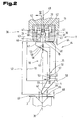
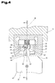
- FIGS. 2 to 4 show in detail the bending tool 4, specifically a disk set 34, formed from a number of tool blades 33 and reference disks 35 arranged on both sides, inserted into the receiving groove 15 of the tool holder 7 of the press beam 13.
- the tool holder 7 is provided with two independently operable, preferably hydromechanical clamping devices 36.
- Clamping elements 37 of the clamping devices 36 are symmetrically opposite with respect to a central axis 38 of the tool holder 7 and in the direction perpendicular to the central axis 38 against the action of a spring arrangement between them 39, with in the receiving groove 15, for clamping the bending tool 4, projecting clamping jaws 40, adjustable by pressurization with a pressure medium.
- pressure chambers 41 are provided in the direction of the length.
- the clamping elements 37 have in the pressure chambers 41 projecting pressure piston 42.
- the tool blades 33 as well as the reference blades 35 are raised - according to arrow 45 - and formed with the central axis 38 in a plane perpendicularly extending abutment surfaces 46 of tool shoulders 47 against support surfaces 48 of the tool holder pressed and are thus the tool blades 33 for making a bending operation on the sheet metal part 3 at an adjustment of the press bar 13 - according to arrow 49 - in working position.
- the disk set 34 is provided in the embodiment shown with two, the tool blades 33 between them receiving fins 35. These are provided with the standard trained clamping straps 44, but are not designed as bending tools, ie that these reference slats 35 only to a partial height 51 of an overall height 52 of the tool blades 33 the Support surface 48 of the tool holder 7 project in the direction of the fixed bending tool 4 in the tool holder 6 of the table beam 10.
- the upper tool 30 formed from the two reference blades 35 and the tool blades arranged between them is combined to form a tool unit via a linear guide device 50, which is formed by two guide rods 53 crossing the entire unit in the direction of the tool length 31, including the reference disks 35, a diameter 54 of the guide rods 53 corresponding holes 55 are provided.
- the tool blades 33 are traversed by the guide rods 53 in slots 56 having a width 57 approximately equal to the diameter 54 and a length 58 approximately equal to twice the diameter 54, the orientation of the slots being in the vertical direction, e.g. in accordance with the adjustment direction - according to arrow 49 - of the press bar 13.
- the recesses 60 of the reference fins 35 relative to the recesses 60 of the tool blades 33 have a vertical offset 61.
- a distance 62 of the recess 60 of the reference blade 35 from the contact surface 46 of the tool shoulder 47 is smaller than a distance 63 of the recess 60 of the tool blade 33 of the contact surface 46 of the tool shoulder 47th
- the upper tool 30 is secured in the receiving groove 15 by positive locking of the clamping elements 37 with the clamping grooves 43 of the reference plates 35 from falling out of the tool holder 7.
- the independent further clamping device 35 which cooperates with the clamping grooves 43 of the tool blades 33, is in the untensioned state, ie, that the clamping jaws 40 of this clamping device 36 is out of engagement with the clamping grooves 43 of the tool blades 33. This causes the tool blades 33 relative to the master blades 50 in the resulting through the slots 56, lowered position - as shown in full lines - are.
- the adjusting movement - according to arrow 49 - of the press bar 13 is released and the adjustment by means of the drives 11, wherein a final clamping of the tool blades 33 by means of the clamping device 36 takes place only after reaching a so-called mute position 66 of a bending edge 67 in which a distance 68 of the bending edge 67 from a workpiece surface 69 is less than about 8 to 12 mm. This ensures that no body part, such as fingers, an operator in this hazardous area.
- the clamping of the tool blades 33 results in an interruption of the reception of the laser beam 29 at the laser beam receiver 15, it is provided in terms of control technology, on reaching the mute position 66, to maintain the progression of the downward movement in order to carry out the bending operation.
- the upward movement of the press bar 13 is carried out to make a further bending operation and activation of the safety device 22, the original state with relaxation of the tool blades 33, so that the uninterrupted beam channel 65, by the aligned position of the recesses 60, restored.
- the safety device 22 it is also possible to control the function of the relative movability of the tool blades 33 prior to the initiation of the downward movement of the press beam 13, e.g. by a clamping operation and immediately following relaxation process of the tool blades 33 in the upper end position of the press bar 13. If after unwinding the uninterrupted beam channel 65 is not restored by taking the hanging position of the tool blades 33, and thus no light beam passage is present, no downward movement of the press bar is possible and will this condition eg indicated by a fault message.
- the individual weight of the tool blade 33 which results from the mass of the tool blade 33, should be approximately between 80N and 250N, preferably 150N.
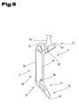
- This limitation is achieved on the one hand by determining the thickness 32 as a function of the total surface of the tool blade 33, wherein larger thicknesses are possible when so-called, optimized in terms of strength, skeletal tools 71 are used as such a tool blade 33 is shown in Fig. 6 , By means of such skeleton tools 71, the number of tool blades 33 to be used for a given tool length 31 can be substantially reduced by the possibility of choosing a larger thickness 32, thus simplifying the retrofitting of tool sets.
- Such a skeleton tool 71 consists of the clamping extension 44 for clamping in the tool holder 7 and a bending edge 67th This consists of a the Sicilschultem 47 with the contact surfaces 46 forming web frame 76 and the bending edge 67 forming web skeleton 77. These are connected for example by a pull rod 78 and an approximately parallel pressure rod 79. Also possible is the formation of guide means 80th For example, the slots 56, the relative adjustability for the use of the skeleton tool 71 with the safety device - as described in the previous examples - guaranteed.
- a surface portion of the rib frame 76, 77 and tension and compression rod 78, 79 between 5% and 30% of a determined by the outer contour of the punch extension 75 total area.
Landscapes
- Engineering & Computer Science (AREA)
- Mechanical Engineering (AREA)
- General Engineering & Computer Science (AREA)
- Bending Of Plates, Rods, And Pipes (AREA)
- Press Drives And Press Lines (AREA)
- Hand Tools For Fitting Together And Separating, Or Other Hand Tools (AREA)
- Mounting, Exchange, And Manufacturing Of Dies (AREA)
Priority Applications (2)
| Application Number | Priority Date | Filing Date | Title |
|---|---|---|---|
| AT06013881T ATE408466T1 (de) | 2005-07-06 | 2006-07-05 | Sicherheitseinrichtung für eine abkantpresse und ein lamellenwerkzeug |
| EP08011998A EP1985386B1 (fr) | 2005-07-06 | 2006-07-05 | Outil de cintrage pour une presse plieuse |
Applications Claiming Priority (1)
| Application Number | Priority Date | Filing Date | Title |
|---|---|---|---|
| AT0113805A AT502038B1 (de) | 2005-07-06 | 2005-07-06 | Sicherheitseinrichtung für eine abkantpresse und ein lamellenwerkzeug |
Related Child Applications (1)
| Application Number | Title | Priority Date | Filing Date |
|---|---|---|---|
| EP08011998A Division EP1985386B1 (fr) | 2005-07-06 | 2006-07-05 | Outil de cintrage pour une presse plieuse |
Publications (3)
| Publication Number | Publication Date |
|---|---|
| EP1741501A2 true EP1741501A2 (fr) | 2007-01-10 |
| EP1741501A3 EP1741501A3 (fr) | 2007-03-14 |
| EP1741501B1 EP1741501B1 (fr) | 2008-09-17 |
Family
ID=37188941
Family Applications (2)
| Application Number | Title | Priority Date | Filing Date |
|---|---|---|---|
| EP06013881A Active EP1741501B1 (fr) | 2005-07-06 | 2006-07-05 | Dispositif de securité pour une presse plieuse et outil à lamelles |
| EP08011998A Not-in-force EP1985386B1 (fr) | 2005-07-06 | 2006-07-05 | Outil de cintrage pour une presse plieuse |
Family Applications After (1)
| Application Number | Title | Priority Date | Filing Date |
|---|---|---|---|
| EP08011998A Not-in-force EP1985386B1 (fr) | 2005-07-06 | 2006-07-05 | Outil de cintrage pour une presse plieuse |
Country Status (5)
| Country | Link |
|---|---|
| US (1) | US7784317B2 (fr) |
| EP (2) | EP1741501B1 (fr) |
| AT (3) | AT502038B1 (fr) |
| DE (2) | DE502006005431D1 (fr) |
| PT (1) | PT1741501E (fr) |
Cited By (4)
| Publication number | Priority date | Publication date | Assignee | Title |
|---|---|---|---|---|
| WO2010022426A1 (fr) * | 2008-08-28 | 2010-03-04 | Trumpf Maschinen Austria Gmbh & Co. Kg. | Outil de cintrage destiné à une presse de cintrage de tôles et son procédé de réalisation |
| WO2011021986A1 (fr) | 2009-08-18 | 2011-02-24 | Demirer Teknolojik Sistemler Sanayi Ticaret Limited Sirketi | Économie dénergie dans des presses hydrauliques à cintrer |
| WO2011138157A1 (fr) * | 2010-05-06 | 2011-11-10 | Trumpf Werkzeugmaschinen Gmbh + Co. Kg | Porte-outil, machine-outil comprenant un tel porte-outil, et procédé pour fixer un outil d'usinage sur un porte-outil d'une machine-outil |
| CN106734728A (zh) * | 2016-12-25 | 2017-05-31 | 信宜华宇电子科技有限公司 | 一种冲压设备的防压手装置 |
Families Citing this family (7)
| Publication number | Priority date | Publication date | Assignee | Title |
|---|---|---|---|---|
| AT508923B1 (de) * | 2009-11-10 | 2011-05-15 | Trumpf Maschinen Austria Gmbh | Fertigungsanlage, insbesondere für das freiformbiegen |
| CN102069137B (zh) * | 2010-11-24 | 2012-09-12 | 中冶京诚工程技术有限公司 | 快锻机活动横梁止动机构 |
| CN104741453B (zh) * | 2015-03-23 | 2016-09-21 | 柳州市富城机械有限责任公司 | 一种汽车后地板横梁成形模具 |
| JP7194644B2 (ja) * | 2019-05-30 | 2022-12-22 | 株式会社アマダ | プレスブレーキの安全装置及びプレスブレーキの安全装置の制御方法 |
| NL2026130B1 (en) * | 2020-07-24 | 2022-03-28 | Wila Bv | Clamping system for a press brake having an integrally formed cavity or chamber and press brake comprising such a clamping system |
| EP4059678B1 (fr) * | 2021-03-17 | 2023-06-07 | Krug & Priester GmbH & Co. KG | Procédé et machine de coupe avec inversement par contrôle sécuritaire du mouvement dangereux de la lame de coupe en cas de danger |
| CN113680923B (zh) * | 2021-10-27 | 2021-12-28 | 江苏颐柏机械有限公司 | 一种金属折弯机的紧急保护装置 |
Family Cites Families (17)
| Publication number | Priority date | Publication date | Assignee | Title |
|---|---|---|---|---|
| LU62956A1 (fr) * | 1970-04-09 | 1971-08-26 | ||
| DE3418108A1 (de) * | 1984-05-16 | 1985-11-21 | Rainer Dipl.-Ing. 7000 Stuttgart Brockmann | Werkzeugmaschine mit sicherheitsvorrichtung |
| CH665364A5 (fr) * | 1985-10-30 | 1988-05-13 | Cybelec Sa | Dispositif pour le controle automatique de l'operation de pliage lors du pliage avec une presse-plieuse. |
| AU667057B2 (en) * | 1991-10-18 | 1996-03-07 | Thomas John Appleyard | Brake press safety apparatus |
| DE4409556A1 (de) * | 1994-03-19 | 1995-09-21 | Blz Bayrisches Laserzentrum Ge | Biegewerkzeug, insbesondere für das Gesenkbiegen |
| US5878619A (en) * | 1998-02-09 | 1999-03-09 | Walczak; Kenneth H. | Laminated punch and die assemblies |
| AT408026B (de) * | 2000-02-04 | 2001-08-27 | Trumpf Maschinen Austria Gmbh | Sicherheitseinrichtung für eine fertigungsmaschine, z.b. eine abkantpresse |
| DE10027156A1 (de) * | 2000-05-31 | 2001-12-06 | Fiessler Elektronik Ohg | Schutzeinrichtung für Maschinen, wie Abkantpressen, Schneidmaschinen, Stanzmaschinen oder dergleichen |
| US6389860B1 (en) * | 2000-08-11 | 2002-05-21 | Lion Machinery, Inc. | Control system for a press brake |
| DE10123562A1 (de) * | 2001-05-15 | 2002-11-21 | Fiessler Elektronik Ohg | Schutzeinrichtung für Maschinen, wie Abkantpressen, Schneidemaschinen, Stanzmaschinen oder dergleichen |
| DE10143505B4 (de) * | 2001-09-05 | 2010-07-08 | Sick Ag | Sicherungsverfahren und optoelektronischer Sensor |
| EP1319886B1 (fr) * | 2001-12-13 | 2005-12-28 | Fiessler Elektronik GmbH & Co. KG | Dispositif de protection pour machines telles que presses-plieuses, découpeuses, machines à éstamper ou analogues |
| DE20217426U1 (de) * | 2002-11-05 | 2003-01-16 | Pilz GmbH & Co., 73760 Ostfildern | Sicherheitseinrichtung für eine Maschine, insbesondere für eine Biegepresse |
| DE10309399A1 (de) * | 2003-03-04 | 2004-09-16 | Sick Ag | Sicherungsverfahren und optoelektronischer Sensor |
| DE10327388C5 (de) * | 2003-06-18 | 2011-12-08 | Leuze Lumiflex Gmbh + Co. Kg | Schutzeinrichtung |
| WO2005030410A1 (fr) * | 2003-09-26 | 2005-04-07 | Trumpf Maschinen Austria Gmbh & Co. Kg. | Systeme de securite comportant un dispositif de fixation reglable en hauteur |
| DE102004020024A1 (de) * | 2004-04-23 | 2005-11-10 | Sick Ag | Verfahren zur Sicherung einer Werkzeugmaschine und optoelektronischer Sensor zur Durchführung eines solchen Verfahrens |
-
2005
- 2005-07-06 AT AT0113805A patent/AT502038B1/de not_active IP Right Cessation
-
2006
- 2006-07-05 EP EP06013881A patent/EP1741501B1/fr active Active
- 2006-07-05 EP EP08011998A patent/EP1985386B1/fr not_active Not-in-force
- 2006-07-05 DE DE502006005431T patent/DE502006005431D1/de active Active
- 2006-07-05 PT PT06013881T patent/PT1741501E/pt unknown
- 2006-07-05 AT AT06013881T patent/ATE408466T1/de active
- 2006-07-05 AT AT08011998T patent/ATE448892T1/de active
- 2006-07-05 DE DE502006001580T patent/DE502006001580D1/de active Active
- 2006-07-06 US US11/428,927 patent/US7784317B2/en not_active Expired - Fee Related
Cited By (7)
| Publication number | Priority date | Publication date | Assignee | Title |
|---|---|---|---|---|
| WO2010022426A1 (fr) * | 2008-08-28 | 2010-03-04 | Trumpf Maschinen Austria Gmbh & Co. Kg. | Outil de cintrage destiné à une presse de cintrage de tôles et son procédé de réalisation |
| WO2011021986A1 (fr) | 2009-08-18 | 2011-02-24 | Demirer Teknolojik Sistemler Sanayi Ticaret Limited Sirketi | Économie dénergie dans des presses hydrauliques à cintrer |
| WO2011138157A1 (fr) * | 2010-05-06 | 2011-11-10 | Trumpf Werkzeugmaschinen Gmbh + Co. Kg | Porte-outil, machine-outil comprenant un tel porte-outil, et procédé pour fixer un outil d'usinage sur un porte-outil d'une machine-outil |
| CN102883832A (zh) * | 2010-05-06 | 2013-01-16 | 通快机床两合公司 | 工具保持装置、具有这种工具保持装置的机床以及用于将加工工具固定至机床的工具保持装置的方法 |
| CN102883832B (zh) * | 2010-05-06 | 2014-11-19 | 通快机床两合公司 | 工具保持装置、具有这种工具保持装置的机床以及用于将加工工具固定至机床的工具保持装置的方法 |
| US9302305B2 (en) | 2010-05-06 | 2016-04-05 | Trumpf Werkzeugmaschinen Gmbh + Co. Kg | Tool retention devices and related machine tools and methods |
| CN106734728A (zh) * | 2016-12-25 | 2017-05-31 | 信宜华宇电子科技有限公司 | 一种冲压设备的防压手装置 |
Also Published As
| Publication number | Publication date |
|---|---|
| US20070033982A1 (en) | 2007-02-15 |
| PT1741501E (pt) | 2009-01-12 |
| EP1741501B1 (fr) | 2008-09-17 |
| ATE448892T1 (de) | 2009-12-15 |
| DE502006005431D1 (de) | 2009-12-31 |
| ATE408466T1 (de) | 2008-10-15 |
| EP1741501A3 (fr) | 2007-03-14 |
| AT502038B1 (de) | 2007-01-15 |
| DE502006001580D1 (de) | 2008-10-30 |
| US7784317B2 (en) | 2010-08-31 |
| AT502038A4 (de) | 2007-01-15 |
| EP1985386A1 (fr) | 2008-10-29 |
| EP1985386B1 (fr) | 2009-11-18 |
Similar Documents
| Publication | Publication Date | Title |
|---|---|---|
| AT514930B1 (de) | Hinteranschlageinheit für Biegemaschine | |
| EP1539391B1 (fr) | Outil de cintrage et dispositif porte-outil associe | |
| EP1741501B1 (fr) | Dispositif de securité pour une presse plieuse et outil à lamelles | |
| EP2450149B1 (fr) | Outil doté de zones actives différentes | |
| EP2794142B1 (fr) | Matrice d'un dispositif de poinçonnage et procédé de poinçonnage | |
| AT408026B (de) | Sicherheitseinrichtung für eine fertigungsmaschine, z.b. eine abkantpresse | |
| EP2481492B1 (fr) | Outil de pliage pour le pliage à forme libre de tôles | |
| EP1622731B1 (fr) | Dispositif porte-outil | |
| EP3113892B1 (fr) | Coulisseau porte-outil | |
| EP2497580A1 (fr) | Outil de pliage et agencement d'outil de pliage | |
| DE102014104146B4 (de) | Stanze | |
| DE102020007893B3 (de) | Bearbeitungsmodul für ein Bearbeitungswerkzeug einer Werkzeugmaschine, Bearbeitungswerkzeug und Werkzeugmaschine | |
| EP1293274B1 (fr) | Dispositif pour la coupe à longueur de matériau en forme de fils | |
| DE102012013771B4 (de) | Schneidwerkzeug und mit solchem ausgestattete Schneidvorrichtung | |
| EP3095534B1 (fr) | Cintreuse | |
| DE102018206775B4 (de) | Stanze zum Zerteilen einer Folienbahn, insbesondere für eine Verpackungsmaschine | |
| EP1700673B1 (fr) | Outil de préhension | |
| DE102020203776B4 (de) | Antriebseinrichtung für eine Bearbeitungsvorrichtung | |
| EP2363242B1 (fr) | Appareil de travail manuel | |
| DE728115C (de) | Zusammenschiebbare Fuehrung fuer den Stempelschaft von Lochstempeln | |
| DE10320839B4 (de) | Sicherungsvorrichtung | |
| DE7306363U (de) | Stanzgestell | |
| DE102006009423A1 (de) | Spann- oder Greifvorrichtung | |
| DE2342111B2 (de) | Verfahren und Vorrichtung zum Herstellen von Kanälen in Schaumstoff | |
| DE9200733U1 (de) | Werkzeug zum Verbinden zweier Bauteile |
Legal Events
| Date | Code | Title | Description |
|---|---|---|---|
| PUAI | Public reference made under article 153(3) epc to a published international application that has entered the european phase |
Free format text: ORIGINAL CODE: 0009012 |
|
| AK | Designated contracting states |
Kind code of ref document: A2 Designated state(s): AT BE BG CH CY CZ DE DK EE ES FI FR GB GR HU IE IS IT LI LT LU LV MC NL PL PT RO SE SI SK TR |
|
| AX | Request for extension of the european patent |
Extension state: AL BA HR MK YU |
|
| PUAL | Search report despatched |
Free format text: ORIGINAL CODE: 0009013 |
|
| AK | Designated contracting states |
Kind code of ref document: A3 Designated state(s): AT BE BG CH CY CZ DE DK EE ES FI FR GB GR HU IE IS IT LI LT LU LV MC NL PL PT RO SE SI SK TR |
|
| AX | Request for extension of the european patent |
Extension state: AL BA HR MK YU |
|
| RIC1 | Information provided on ipc code assigned before grant |
Ipc: B21D 37/10 20060101ALI20070201BHEP Ipc: B21D 37/20 20060101ALI20070201BHEP Ipc: B21D 37/02 20060101ALI20070201BHEP Ipc: F16P 3/14 20060101ALI20070201BHEP Ipc: B21D 55/00 20060101AFI20061108BHEP Ipc: B23P 15/24 20060101ALI20070201BHEP Ipc: B30B 15/28 20060101ALI20070201BHEP |
|
| 17P | Request for examination filed |
Effective date: 20070913 |
|
| 17Q | First examination report despatched |
Effective date: 20071018 |
|
| AKX | Designation fees paid |
Designated state(s): AT BE BG CH CY CZ DE DK EE ES FI FR GB GR HU IE IS IT LI LT LU LV MC NL PL PT RO SE SI SK TR |
|
| AXX | Extension fees paid |
Extension state: BA Payment date: 20070913 Extension state: HR Payment date: 20070913 Extension state: MK Payment date: 20070913 Extension state: YU Payment date: 20070913 Extension state: AL Payment date: 20070913 |
|
| GRAP | Despatch of communication of intention to grant a patent |
Free format text: ORIGINAL CODE: EPIDOSNIGR1 |
|
| RAX | Requested extension states of the european patent have changed |
Extension state: MK Payment date: 20070913 Extension state: BA Payment date: 20070913 Extension state: HR Payment date: 20070913 Extension state: AL Payment date: 20070913 Extension state: RS Payment date: 20070913 |
|
| GRAS | Grant fee paid |
Free format text: ORIGINAL CODE: EPIDOSNIGR3 |
|
| GRAA | (expected) grant |
Free format text: ORIGINAL CODE: 0009210 |
|
| AK | Designated contracting states |
Kind code of ref document: B1 Designated state(s): AT BE BG CH CY CZ DE DK EE ES FI FR GB GR HU IE IS IT LI LT LU LV MC NL PL PT RO SE SI SK TR |
|
| AX | Request for extension of the european patent |
Extension state: AL BA HR MK RS |
|
| REG | Reference to a national code |
Ref country code: GB Ref legal event code: FG4D Free format text: NOT ENGLISH |
|
| REG | Reference to a national code |
Ref country code: CH Ref legal event code: EP |
|
| REG | Reference to a national code |
Ref country code: IE Ref legal event code: FG4D Free format text: LANGUAGE OF EP DOCUMENT: GERMAN |
|
| REF | Corresponds to: |
Ref document number: 502006001580 Country of ref document: DE Date of ref document: 20081030 Kind code of ref document: P |
|
| REG | Reference to a national code |
Ref country code: PT Ref legal event code: SC4A Free format text: AVAILABILITY OF NATIONAL TRANSLATION Effective date: 20081230 |
|
| PG25 | Lapsed in a contracting state [announced via postgrant information from national office to epo] |
Ref country code: LT Free format text: LAPSE BECAUSE OF FAILURE TO SUBMIT A TRANSLATION OF THE DESCRIPTION OR TO PAY THE FEE WITHIN THE PRESCRIBED TIME-LIMIT Effective date: 20080917 |
|
| PG25 | Lapsed in a contracting state [announced via postgrant information from national office to epo] |
Ref country code: SI Free format text: LAPSE BECAUSE OF FAILURE TO SUBMIT A TRANSLATION OF THE DESCRIPTION OR TO PAY THE FEE WITHIN THE PRESCRIBED TIME-LIMIT Effective date: 20080917 Ref country code: LV Free format text: LAPSE BECAUSE OF FAILURE TO SUBMIT A TRANSLATION OF THE DESCRIPTION OR TO PAY THE FEE WITHIN THE PRESCRIBED TIME-LIMIT Effective date: 20080917 Ref country code: FI Free format text: LAPSE BECAUSE OF FAILURE TO SUBMIT A TRANSLATION OF THE DESCRIPTION OR TO PAY THE FEE WITHIN THE PRESCRIBED TIME-LIMIT Effective date: 20080917 |
|
| REG | Reference to a national code |
Ref country code: IE Ref legal event code: FD4D |
|
| PG25 | Lapsed in a contracting state [announced via postgrant information from national office to epo] |
Ref country code: BG Free format text: LAPSE BECAUSE OF FAILURE TO SUBMIT A TRANSLATION OF THE DESCRIPTION OR TO PAY THE FEE WITHIN THE PRESCRIBED TIME-LIMIT Effective date: 20081217 Ref country code: ES Free format text: LAPSE BECAUSE OF FAILURE TO SUBMIT A TRANSLATION OF THE DESCRIPTION OR TO PAY THE FEE WITHIN THE PRESCRIBED TIME-LIMIT Effective date: 20081228 |
|
| PG25 | Lapsed in a contracting state [announced via postgrant information from national office to epo] |
Ref country code: RO Free format text: LAPSE BECAUSE OF FAILURE TO SUBMIT A TRANSLATION OF THE DESCRIPTION OR TO PAY THE FEE WITHIN THE PRESCRIBED TIME-LIMIT Effective date: 20080917 Ref country code: IS Free format text: LAPSE BECAUSE OF FAILURE TO SUBMIT A TRANSLATION OF THE DESCRIPTION OR TO PAY THE FEE WITHIN THE PRESCRIBED TIME-LIMIT Effective date: 20090117 |
|
| PLBE | No opposition filed within time limit |
Free format text: ORIGINAL CODE: 0009261 |
|
| STAA | Information on the status of an ep patent application or granted ep patent |
Free format text: STATUS: NO OPPOSITION FILED WITHIN TIME LIMIT |
|
| PG25 | Lapsed in a contracting state [announced via postgrant information from national office to epo] |
Ref country code: EE Free format text: LAPSE BECAUSE OF FAILURE TO SUBMIT A TRANSLATION OF THE DESCRIPTION OR TO PAY THE FEE WITHIN THE PRESCRIBED TIME-LIMIT Effective date: 20080917 Ref country code: IE Free format text: LAPSE BECAUSE OF FAILURE TO SUBMIT A TRANSLATION OF THE DESCRIPTION OR TO PAY THE FEE WITHIN THE PRESCRIBED TIME-LIMIT Effective date: 20080917 Ref country code: DK Free format text: LAPSE BECAUSE OF FAILURE TO SUBMIT A TRANSLATION OF THE DESCRIPTION OR TO PAY THE FEE WITHIN THE PRESCRIBED TIME-LIMIT Effective date: 20080917 |
|
| 26N | No opposition filed |
Effective date: 20090618 |
|
| PG25 | Lapsed in a contracting state [announced via postgrant information from national office to epo] |
Ref country code: SE Free format text: LAPSE BECAUSE OF FAILURE TO SUBMIT A TRANSLATION OF THE DESCRIPTION OR TO PAY THE FEE WITHIN THE PRESCRIBED TIME-LIMIT Effective date: 20081217 |
|
| BERE | Be: lapsed |
Owner name: TRUMPF MASCHINEN AUSTRIA GMBH & CO. KG. Effective date: 20090731 |
|
| PG25 | Lapsed in a contracting state [announced via postgrant information from national office to epo] |
Ref country code: MC Free format text: LAPSE BECAUSE OF NON-PAYMENT OF DUE FEES Effective date: 20090731 |
|
| PG25 | Lapsed in a contracting state [announced via postgrant information from national office to epo] |
Ref country code: PL Free format text: LAPSE BECAUSE OF FAILURE TO SUBMIT A TRANSLATION OF THE DESCRIPTION OR TO PAY THE FEE WITHIN THE PRESCRIBED TIME-LIMIT Effective date: 20080917 |
|
| PG25 | Lapsed in a contracting state [announced via postgrant information from national office to epo] |
Ref country code: BE Free format text: LAPSE BECAUSE OF NON-PAYMENT OF DUE FEES Effective date: 20090731 |
|
| PG25 | Lapsed in a contracting state [announced via postgrant information from national office to epo] |
Ref country code: GR Free format text: LAPSE BECAUSE OF FAILURE TO SUBMIT A TRANSLATION OF THE DESCRIPTION OR TO PAY THE FEE WITHIN THE PRESCRIBED TIME-LIMIT Effective date: 20081218 |
|
| REG | Reference to a national code |
Ref country code: CH Ref legal event code: PL |
|
| GBPC | Gb: european patent ceased through non-payment of renewal fee |
Effective date: 20100705 |
|
| PG25 | Lapsed in a contracting state [announced via postgrant information from national office to epo] |
Ref country code: LU Free format text: LAPSE BECAUSE OF NON-PAYMENT OF DUE FEES Effective date: 20090705 Ref country code: CH Free format text: LAPSE BECAUSE OF NON-PAYMENT OF DUE FEES Effective date: 20100731 Ref country code: LI Free format text: LAPSE BECAUSE OF NON-PAYMENT OF DUE FEES Effective date: 20100731 |
|
| PG25 | Lapsed in a contracting state [announced via postgrant information from national office to epo] |
Ref country code: HU Free format text: LAPSE BECAUSE OF FAILURE TO SUBMIT A TRANSLATION OF THE DESCRIPTION OR TO PAY THE FEE WITHIN THE PRESCRIBED TIME-LIMIT Effective date: 20090318 |
|
| PG25 | Lapsed in a contracting state [announced via postgrant information from national office to epo] |
Ref country code: GB Free format text: LAPSE BECAUSE OF NON-PAYMENT OF DUE FEES Effective date: 20100705 |
|
| PG25 | Lapsed in a contracting state [announced via postgrant information from national office to epo] |
Ref country code: CY Free format text: LAPSE BECAUSE OF FAILURE TO SUBMIT A TRANSLATION OF THE DESCRIPTION OR TO PAY THE FEE WITHIN THE PRESCRIBED TIME-LIMIT Effective date: 20080917 |
|
| REG | Reference to a national code |
Ref country code: FR Ref legal event code: PLFP Year of fee payment: 10 |
|
| REG | Reference to a national code |
Ref country code: FR Ref legal event code: PLFP Year of fee payment: 11 |
|
| PGFP | Annual fee paid to national office [announced via postgrant information from national office to epo] |
Ref country code: CZ Payment date: 20160620 Year of fee payment: 11 |
|
| PGFP | Annual fee paid to national office [announced via postgrant information from national office to epo] |
Ref country code: SK Payment date: 20160616 Year of fee payment: 11 Ref country code: TR Payment date: 20160629 Year of fee payment: 11 Ref country code: PT Payment date: 20160624 Year of fee payment: 11 |
|
| PGFP | Annual fee paid to national office [announced via postgrant information from national office to epo] |
Ref country code: AT Payment date: 20160714 Year of fee payment: 11 |
|
| REG | Reference to a national code |
Ref country code: FR Ref legal event code: PLFP Year of fee payment: 12 |
|
| PGFP | Annual fee paid to national office [announced via postgrant information from national office to epo] |
Ref country code: FR Payment date: 20170619 Year of fee payment: 12 |
|
| PGFP | Annual fee paid to national office [announced via postgrant information from national office to epo] |
Ref country code: NL Payment date: 20170620 Year of fee payment: 12 Ref country code: IT Payment date: 20170614 Year of fee payment: 12 |
|
| PGFP | Annual fee paid to national office [announced via postgrant information from national office to epo] |
Ref country code: DE Payment date: 20170619 Year of fee payment: 12 |
|
| PG25 | Lapsed in a contracting state [announced via postgrant information from national office to epo] |
Ref country code: CZ Free format text: LAPSE BECAUSE OF NON-PAYMENT OF DUE FEES Effective date: 20170705 |
|
| REG | Reference to a national code |
Ref country code: AT Ref legal event code: MM01 Ref document number: 408466 Country of ref document: AT Kind code of ref document: T Effective date: 20170705 |
|
| REG | Reference to a national code |
Ref country code: SK Ref legal event code: MM4A Ref document number: E 5142 Country of ref document: SK Effective date: 20170705 |
|
| PG25 | Lapsed in a contracting state [announced via postgrant information from national office to epo] |
Ref country code: SK Free format text: LAPSE BECAUSE OF NON-PAYMENT OF DUE FEES Effective date: 20170705 Ref country code: PT Free format text: LAPSE BECAUSE OF NON-PAYMENT OF DUE FEES Effective date: 20180105 Ref country code: AT Free format text: LAPSE BECAUSE OF NON-PAYMENT OF DUE FEES Effective date: 20170705 |
|
| REG | Reference to a national code |
Ref country code: DE Ref legal event code: R119 Ref document number: 502006001580 Country of ref document: DE |
|
| REG | Reference to a national code |
Ref country code: DE Ref legal event code: R082 Ref document number: 502006001580 Country of ref document: DE Representative=s name: ABP BURGER RECHTSANWALTSGESELLSCHAFT MBH, DE |
|
| REG | Reference to a national code |
Ref country code: NL Ref legal event code: MM Effective date: 20180801 |
|
| PG25 | Lapsed in a contracting state [announced via postgrant information from national office to epo] |
Ref country code: FR Free format text: LAPSE BECAUSE OF NON-PAYMENT OF DUE FEES Effective date: 20180731 Ref country code: DE Free format text: LAPSE BECAUSE OF NON-PAYMENT OF DUE FEES Effective date: 20190201 |
|
| PG25 | Lapsed in a contracting state [announced via postgrant information from national office to epo] |
Ref country code: NL Free format text: LAPSE BECAUSE OF NON-PAYMENT OF DUE FEES Effective date: 20180801 |
|
| PG25 | Lapsed in a contracting state [announced via postgrant information from national office to epo] |
Ref country code: IT Free format text: LAPSE BECAUSE OF NON-PAYMENT OF DUE FEES Effective date: 20180705 |
|
| PG25 | Lapsed in a contracting state [announced via postgrant information from national office to epo] |
Ref country code: TR Free format text: LAPSE BECAUSE OF NON-PAYMENT OF DUE FEES Effective date: 20170705 |