EP1741608A1 - Bremskraftverstärker mit zwei Verstärkungsfaktoren - Google Patents
Bremskraftverstärker mit zwei Verstärkungsfaktoren Download PDFInfo
- Publication number
- EP1741608A1 EP1741608A1 EP05300553A EP05300553A EP1741608A1 EP 1741608 A1 EP1741608 A1 EP 1741608A1 EP 05300553 A EP05300553 A EP 05300553A EP 05300553 A EP05300553 A EP 05300553A EP 1741608 A1 EP1741608 A1 EP 1741608A1
- Authority
- EP
- European Patent Office
- Prior art keywords
- piston
- transmission member
- reaction
- plunger
- amplifier according
- Prior art date
- Legal status (The legal status is an assumption and is not a legal conclusion. Google has not performed a legal analysis and makes no representation as to the accuracy of the status listed.)
- Granted
Links
- 230000003321 amplification Effects 0.000 title claims description 14
- 238000003199 nucleic acid amplification method Methods 0.000 title claims description 14
- 238000006243 chemical reaction Methods 0.000 claims abstract description 76
- 230000008878 coupling Effects 0.000 claims abstract description 28
- 238000010168 coupling process Methods 0.000 claims abstract description 28
- 238000005859 coupling reaction Methods 0.000 claims abstract description 28
- 230000005540 biological transmission Effects 0.000 claims description 53
- 239000012528 membrane Substances 0.000 claims description 13
- 230000002093 peripheral effect Effects 0.000 claims description 10
- 239000013536 elastomeric material Substances 0.000 claims description 3
- 230000004044 response Effects 0.000 claims description 2
- 210000000056 organ Anatomy 0.000 claims 1
- 239000002775 capsule Substances 0.000 description 6
- 239000000463 material Substances 0.000 description 5
- 238000012550 audit Methods 0.000 description 4
- 230000000994 depressogenic effect Effects 0.000 description 4
- 238000006073 displacement reaction Methods 0.000 description 4
- 230000000694 effects Effects 0.000 description 4
- 238000004519 manufacturing process Methods 0.000 description 4
- 230000008901 benefit Effects 0.000 description 3
- 230000009471 action Effects 0.000 description 2
- 230000008859 change Effects 0.000 description 2
- 238000005192 partition Methods 0.000 description 2
- 229910000831 Steel Inorganic materials 0.000 description 1
- 239000002184 metal Substances 0.000 description 1
- 238000004080 punching Methods 0.000 description 1
- 239000010959 steel Substances 0.000 description 1
- 230000001960 triggered effect Effects 0.000 description 1
Images
Classifications
-
- B—PERFORMING OPERATIONS; TRANSPORTING
- B60—VEHICLES IN GENERAL
- B60T—VEHICLE BRAKE CONTROL SYSTEMS OR PARTS THEREOF; BRAKE CONTROL SYSTEMS OR PARTS THEREOF, IN GENERAL; ARRANGEMENT OF BRAKING ELEMENTS ON VEHICLES IN GENERAL; PORTABLE DEVICES FOR PREVENTING UNWANTED MOVEMENT OF VEHICLES; VEHICLE MODIFICATIONS TO FACILITATE COOLING OF BRAKES
- B60T13/00—Transmitting braking action from initiating means to ultimate brake actuator with power assistance or drive; Brake systems incorporating such transmitting means, e.g. air-pressure brake systems
- B60T13/10—Transmitting braking action from initiating means to ultimate brake actuator with power assistance or drive; Brake systems incorporating such transmitting means, e.g. air-pressure brake systems with fluid assistance, drive, or release
- B60T13/24—Transmitting braking action from initiating means to ultimate brake actuator with power assistance or drive; Brake systems incorporating such transmitting means, e.g. air-pressure brake systems with fluid assistance, drive, or release the fluid being gaseous
- B60T13/46—Vacuum systems
- B60T13/52—Vacuum systems indirect, i.e. vacuum booster units
- B60T13/573—Vacuum systems indirect, i.e. vacuum booster units characterised by reaction devices
- B60T13/575—Vacuum systems indirect, i.e. vacuum booster units characterised by reaction devices using resilient discs or pads
Definitions
- the present invention relates to a power amplifier with two amplification ratios for the emergency braking assistance of a motor vehicle.
- Vacuum force amplifiers including those equipped with an emergency brake assist system (AFU system, also referred to as "Panic Assist” by those skilled in the art) are now well known.
- AFU system also referred to as "Panic Assist” by those skilled in the art
- the document FR 2,857,641 discloses an amplifier having an emergency brake assist function, wherein an output member comprises a detachable coupling responsive to an actuating speed.
- This coupling is an elaborate system with many parts. In addition, it involves a setting operation when installed on the amplifier.
- the document EP 1,522,479 describes an amplifier in which a variable coupling is provided by a deformable elastic capsule inside which a reaction element is mounted. In emergency braking, the capsule is deformed so that an axial clearance between the capsule and a push rod is removed, which has the effect of modifying the coupling ratio.
- the amplifier described by this document has several disadvantages. It is necessary to mold the reaction element inside the capsule. It is therefore not possible to manufacture these two elements independently.
- the shape of the reaction element must correspond to that of the capsule, which is imposed by the elastic properties that the capsule must present in order to be deformed. It is therefore not possible to use this device with a reaction element of any shape, for example a conventional disk-shaped reaction element.
- the invention aims to provide an amplifier that does not present at least some of the aforementioned drawbacks of the prior art.
- the transmission member and the reaction element can be independently manufactured, and easily associated during assembly of the amplifier, for example by sliding the receiving part around the reaction element.
- the reaction element may be of arbitrary form, for example in the form of a disk. It is therefore possible to install such a transmission member on amplifiers having a conventional reaction disc.
- the transmission member must not deform substantially during operation of the amplifier, especially at its receiving portion.
- This part can therefore be dimensioned and made of material chosen to withstand the internal pressure of the reaction element.
- the influence of the thermal expansion of the reaction element on the game is limited because this thermal expansion does not necessarily imply a deformation of the transmission member, since they can slide relative to each other. the other.
- At least a portion of the receiving portion is arranged around the piston in the uncoupled position of the transmission member and is slidable relative to the piston.
- the piston provides guiding of the transmission member.
- the receiving part is guided so as to slide in the forward and reverse directions.
- the transmission member is rigid.
- the amplifier comprises an elastic biasing means arranged so as to urge the transmission member towards a rear position relative to the output member, so that the game is formed only between the part before the transmission member and the output member in the decoupled position of the transmission member.
- the resilient biasing means cooperates on the one hand with a fixed support member relative to said piston, and on the other hand with a fixed support member relative to said transmission member.
- the elastic properties of the elastic biasing means are independent of the shape and the material of the transmission member. These properties can therefore be chosen in an optimized manner, without manufacturing constraints imposed by the transmission member.
- the elastic properties of the elastic biasing means make it possible to impose the moment of passage of the transmission member between the decoupled and coupled positions. It is thus possible to reliably and sustainably regulate the dynamic conditions in which the change of amplification ratio takes place by substantially reducing or canceling the influence of the elastic properties of the reaction element itself, which vary greatly according to wear and temperature, on these dynamic conditions.
- said resilient biasing means comprises a helical spring arranged between said fixed support member with respect to said piston and said fixed support member with respect to said transmission member.
- said transmission member has a bearing flange, said support member fixed relative to said transmission member comprising said support flange.
- said piston comprises a skirt extending beyond said fixed support member relative to said transmission member in the forward direction, said support member fixed relative to said piston comprising at least one pin fixed projecting from said at least one skirt.
- said output member comprises a cylindrical rear portion, said front portion of the transmission member being slidably guided around said rear portion of the output member.
- said output member has a collar, said front portion of the transmission member cooperating with said collar in the coupled position of the transmission member.
- the coupling between said piston and said rear face of the reaction element is direct contact coupling.
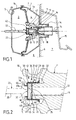
- the term “front” and “rear” respectively designates the left and the right of FIG. 1.
- the invention is not limited to a force amplifier intended to be mounted in a motor vehicle. with the elements shown on the left, respectively on the right, of FIG. 1, arranged towards the front, respectively towards the rear of the vehicle.
- the "forward” and “rear” directions may coincide, but do not necessarily coincide with what is commonly referred to as the front and rear of the vehicle.
- the force amplifier shown in Figure 1 comprises a casing 1, which is composed of two parts 1a and 1b, respectively rear and front, which are assembled to one another by punching.
- a membrane 2 divides the internal volume of the casing 1 into a front chamber 3 connected to a relatively low pressure source (usually a pressure lower than the atmospheric pressure supplied by the engine air intake circuit) and to a rear chamber or working chamber 4 which can be selectively connected to a relatively high pressure source (usually atmospheric pressure).
- the front portion 1b of the casing 1 is provided with a connection 5 through which the chamber 3 can be connected, via a suitable pipe not shown, to a vacuum source.
- the rear portion 1a of the casing 1 is usually fixed, by means not shown, to a partition 6 separating the passenger compartment 7 of a vehicle relative to the engine compartment 8 of said vehicle.
- the rear portion 1a of the casing 1 comprises a cylindrical portion 1c which passes through an opening 9 of the partition 6 and which opens into the passenger compartment 7.
- a piston 11 (primary piston also called valve body), which is attached to the membrane 2 and which is axially movable with it in the casing 1 and in the cylindrical portion 1c of the rear portion 1a.
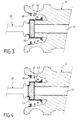
- a plunger 12 can slide in an axial bore 13 of the piston 11 and can be moved in said bore, under the control of a force input member or actuator 14, from the stable rest position shown in FIG. 2, to an unstable working position, to the left in FIG. 2, that is to the front portion 1b of the casing 1.
- the actuating member 14 can be constituted by a control rod connected to the brake pedal 15 of the vehicle.
- the force amplifier further comprises a valve 16 adapted to cooperate with seats 17 and 18 respectively provided on the piston 11 and on the plunger 12.
- a valve 16 adapted to cooperate with seats 17 and 18 respectively provided on the piston 11 and on the plunger 12.
- the seat 17 deviates slightly from the valve 16 and a communication is established between the two chambers 3 and 4 of the casing 1 through passages 19 and 21 formed in the piston 11.
- the control rod pushes the plunger 12 forward into the bore 13 of the piston 11.
- the valve 16 which is also pushed forward by a spring not shown axially bearing against a shoulder of the control rod 14, first comes into contact with the seat 17 to cut the communication between the chambers 3 and 4 of the casing 1.
- the force amplifier further comprises an output member 22, also called a reaction rod, whose front end is usually coupled, in use, to the piston of a master cylinder (not shown) forming part of the braking system. of the vehicle.
- an output member 22 also called a reaction rod, whose front end is usually coupled, in use, to the piston of a master cylinder (not shown) forming part of the braking system. of the vehicle.
- the piston 11 and the plunger 12 act together on the output member 22 via a reaction disk 23 of elastomeric material, to push the output member 22 forward, that is to say to the left in the figure 2.
- the output member 22 transmits an output force to the piston of the master cylinder which will then generate, at the vehicle brakes, a braking pressure proportional to the output force of the amplifier. strength.
- the amplification ratio of the force amplifier is determined approximately by the ratio between, on the one hand, the total contact area of the reaction disk 23 with the end faces of the piston 11 and the plunger 12 and, on the other hand, the contact area between the rear face of the the output member 22 and the reaction disc 23.
- the force amplifier shown in Figure 1 comprises an emergency braking assistance system, which responds to the speed of actuation of the brake pedal 15, to greatly increase the amplification ratio of the amplifier. force when an emergency braking situation is detected.
- an emergency braking assistance system which responds to the speed of actuation of the brake pedal 15, to greatly increase the amplification ratio of the amplifier. force when an emergency braking situation is detected.
- the control rod 14 and the plunger 12 are actuated very rapidly, that is to say at a speed greater than a predefined threshold value VS in principle greater than 100 mm / s, or, what is equivalent, if the plunger 12 performs a stroke greater than a predetermined value, in principle greater than 1 mm, relative to the piston 11.
- the threshold value VS may be equal, for example, to 500 mm / s.
- the force amplifier may have an amplification ratio of a first value Q1 equal, for example, to about 5 when the operating speed of the control rod 14 and the plunger 12 is lower than VS, and a second value Q2 equal, for example, to about 14 when said operating speed is greater than VS.
- the air valve 16, 18 must be sufficiently open, that is to say that the plunger 12 must be moved forwards (to the left in FIG. sufficient amount relative to the piston 11, this amount usually varies between about 0.5 and about 0.8 mm depending on the models and manufacturers of force amplifiers. This is why it is generally agreed to refer to "emergency braking mode" for a diver stroke greater than 1 mm, for example 1.5 ⁇ 0.4 mm ( ⁇ 0.4 mm are to account for manufacturing and mounting tolerances). Thus, if the plunger 12 advances more than 1.5 ⁇ 0.4 mm with respect to the piston 12, the emergency braking mode will be triggered.
- the piston 11 comprises a circular outer skirt 30, to which the membrane 2 is fixed at a circular receiving notch 31.
- the piston 11 Inside the outer skirt 30, the piston 11 has an inner skirt 32, circular cylindrical, which has a front face 33 annular.
- the bore 13 passes through the skirt 32.
- the plunger 12 has a front face 34.
- the reaction disk 23 is of circular cylindrical shape. It has a rear face 35, a lateral face 36, and a front face 37. It is arranged at the front ends of the skirt 32 and the plunger 12, so that the rear face 35 can cooperate with the end faces 33 and 34.
- the output member 22 has a circular cylindrical front portion 38 intended to cooperate with the piston of a hydraulic master cylinder at its front end, and a rear portion 39, also circular cylindrical and of diameter greater than the diameter. of the portion 38.
- the rear portion 39 has a rear face 41 which can cooperate with a central portion 37a circular of the front face 37 of the reaction disk 23.
- the member of outlet comprises a collar 40 which protrudes radially from the rear portion 39 so as to have a shoulder surface 60 facing rearwardly.
- the force amplifier comprises a liner 42, comprising a cylindrical front portion 43, which surrounds the rear portion 39 of the output member 22 and is slidable forward and rearward about the portion 39.
- the liner 42 also comprises an annular coupling portion 44, which projects radially from the front portion 43 and can cooperate with an annular peripheral portion 37b of the front face 37 of the reaction disk 23.
- the jacket 42 has a portion of receiving 45, of diameter corresponding to that of the reaction disc 23 and the inner skirt 32, which surrounds the reaction disc 23 and the inner skirt 32 and can slide relative thereto.
- the receiving portion 45 is connected to the coupling portion 44 at the outer periphery of the portion
- the liner 42 has a flange 46 which projects radially.
- the jacket 42 is for example made by stamping a steel sheet 1 mm thick.
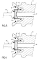
- the liner 42 can slide around the skirt 32, the reaction disc 23 and the rear portion 39 of the output member, between a rear position, shown in FIGS. 2 to 4, and a front position, shown in FIGS. Figures 5 and 6.
- a clearance is provided between the surface 60 of the collar 40 and the front portion 43 of the sleeve 42.
- the coupling between the outlet member 22 and the reaction disk 23 is formed by the contact between the rear face 41 of the output member 22 and the central portion 37a of the front face 37 of the reaction disk 23. This coupling corresponds to the amplification ratio Q1.
- the clearance is cleared and the front portion 43 abuts against the surface 60 of the collar 40.
- the liner 42 provides an additional coupling between the reaction disc and the output member 22, transmitting to the output member 22, via its front portion 43, the contact pressure between its coupling portion 44 and the peripheral portion 37b of the front face 37 of the reaction disk 23. This additional coupling leads to the amplification ratio Q2.
- a helical spring 47 is arranged to bias the liner 42 into the rear position.
- the spring 47 is supported on the one hand on the flange 46, and on another by a support element attached to the piston 11.
- this support element comprises a set of pins 48 attached to the piston 11 by fitting into bores in the outer skirt 30, so as to protrude inwardly of the skirt 30.
- the pins 48 are arranged forward with respect to the flange 46.
- this support member comprises a toothed piece 49 metal, generally annular shape.
- the piece 49 has teeth for fixing the piece 49 to the inner surface of the outer skirt 30, by hooking.
- This variant has the advantage of not requiring to provide bores in the skirt 30.
- the other variant has the advantage that the fixing of the pins 49 is more reliable than attachment by hooking teeth.
- the reaction disc When the brake pedal 15 is not actuated and no braking is applied, the reaction disc has the circular cylindrical shape described above, and the sleeve 42 is positioned in its rear position by the spring 47, as shown in Figures 2 and 3.
- This internal pressure is sufficient to elastically deform the reaction disc 23 so as to "extrude” material at the central portion 37a of its front face 37, which has the effect of transmitting the displacement of the piston 11 and the plunger 12 to the output member 22.
- This internal pressure is in this case insufficient to move the sleeve 42 against the bias of the spring 47.
- the liner 42 remains in its rear position and the amplification ratio Q1 is determined as a function of the area of the central portion 37a with respect to the area of the end faces 33 and 34.
- the sleeve 42 is thus in its forward position and the reaction disc 37 is elastically deformed so that the material is "extruded" At the level of the portion 37b and opposite the front face 33, as shown in FIG. 5.
- an additional coupling between the outlet member 22 and the reaction disk 23 is produced by the jacket 42 and the force amplifier reaches an amplification ratio Q2 which is determined as a function of the total area of the front face 37, that is to say the area of the central portion 37a and the peripheral portion 37b , in relation to the area end faces 33 and 34.
- the threshold internal pressure, above which the sleeve 42 passes in its forward position can be chosen by choosing a spring 47 of corresponding stiffness.
- the force amplifier also has the amplification ratio Q2, although it is in normal braking.
- Q2 is not necessarily equal to twice Q1.
- Normal double-ratio braking is achieved by operating the brake pedal 15 under normal braking, i.e., to move the plunger 12 forward with a speed below VS, but with a force greater than a given threshold. This can be achieved for example by slowly increasing the input force exerted on the brake pedal from the braking state shown in Figure 4, which is a normal single-ratio braking.
- the internal pressure of the reaction disc 23 increases sufficiently to move the sleeve 42 against the biasing of the spring 42 in its forward position.
- the reaction disk 23 is elastically deformed so that material is "extruded" at the portion 37b, as shown in FIG.
- a force amplifier according to the invention may have differences with respect to the amplifier described above.
- the force amplifier could operate without the spring 47.
- the jacket 42 in its decoupled position corresponding to a normal braking, the jacket 42 is positioned floating.
- the clearance is distributed between the collar 40 and the front portion 43 of the liner 42 and the portion 44 of the liner 42 and the peripheral portion 37b of the front face 37 of the reaction disc 23.
- internal pressure threshold above which the reaction disc 23 elastically deforms so as to move the sleeve 42 in its forward position is a function of the elastic properties of the reaction disc 23.
- the invention is applicable to a tandem type force amplifier.
- a force amplifier according to the invention could be designed to have more than two amplification ratios, for example by providing a plurality of decouplable transmission members cooperating with respective portions of the reaction disk.
Landscapes
- Engineering & Computer Science (AREA)
- Transportation (AREA)
- Mechanical Engineering (AREA)
- Braking Systems And Boosters (AREA)
Priority Applications (3)
| Application Number | Priority Date | Filing Date | Title |
|---|---|---|---|
| DE602005003119T DE602005003119T2 (de) | 2005-07-04 | 2005-07-04 | Bremskraftverstärker mit zwei Verstärkungsfaktoren |
| AT05300553T ATE376952T1 (de) | 2005-07-04 | 2005-07-04 | Bremskraftverstärker mit zwei verstärkungsfaktoren |
| EP05300553A EP1741608B1 (de) | 2005-07-04 | 2005-07-04 | Bremskraftverstärker mit zwei Verstärkungsfaktoren |
Applications Claiming Priority (1)
| Application Number | Priority Date | Filing Date | Title |
|---|---|---|---|
| EP05300553A EP1741608B1 (de) | 2005-07-04 | 2005-07-04 | Bremskraftverstärker mit zwei Verstärkungsfaktoren |
Publications (2)
| Publication Number | Publication Date |
|---|---|
| EP1741608A1 true EP1741608A1 (de) | 2007-01-10 |
| EP1741608B1 EP1741608B1 (de) | 2007-10-31 |
Family
ID=34942663
Family Applications (1)
| Application Number | Title | Priority Date | Filing Date |
|---|---|---|---|
| EP05300553A Expired - Lifetime EP1741608B1 (de) | 2005-07-04 | 2005-07-04 | Bremskraftverstärker mit zwei Verstärkungsfaktoren |
Country Status (3)
| Country | Link |
|---|---|
| EP (1) | EP1741608B1 (de) |
| AT (1) | ATE376952T1 (de) |
| DE (1) | DE602005003119T2 (de) |
Cited By (3)
| Publication number | Priority date | Publication date | Assignee | Title |
|---|---|---|---|---|
| EP1961637A1 (de) * | 2007-02-22 | 2008-08-27 | Delphi Technologies, Inc. | Kraftaufnehmer für Bremskraftverstärker-Reaktionsscheibe |
| WO2016034342A1 (de) * | 2014-09-01 | 2016-03-10 | Robert Bosch Gmbh | Bremskraftverstärker für ein bremssystem eines fahrzeugs |
| CN113492820A (zh) * | 2020-04-03 | 2021-10-12 | Zf主动安全有限公司 | 用于机电制动助力器的组件、制动助力器及车辆制动系统 |
Citations (5)
| Publication number | Priority date | Publication date | Assignee | Title |
|---|---|---|---|---|
| US5012723A (en) * | 1988-04-28 | 1991-05-07 | Bendix France | Brake booster |
| US5493948A (en) * | 1992-04-30 | 1996-02-27 | Bendix Europe Services Techniques | Force transmission device for a booster with jump adjustment |
| US5699713A (en) * | 1993-07-01 | 1997-12-23 | Lucas Industries Plc | Brake booster |
| FR2857641A1 (fr) * | 2003-07-16 | 2005-01-21 | Delphi Tech Inc | Amplificateur de force a au moins deux rapports d'amplification |
| EP1522479A1 (de) * | 2003-10-06 | 2005-04-13 | ROBERT BOSCH GmbH | Vakuum Bremskraftverstärker, insbesondere für ein Kraftfahrzeug |
-
2005
- 2005-07-04 EP EP05300553A patent/EP1741608B1/de not_active Expired - Lifetime
- 2005-07-04 AT AT05300553T patent/ATE376952T1/de not_active IP Right Cessation
- 2005-07-04 DE DE602005003119T patent/DE602005003119T2/de not_active Expired - Lifetime
Patent Citations (5)
| Publication number | Priority date | Publication date | Assignee | Title |
|---|---|---|---|---|
| US5012723A (en) * | 1988-04-28 | 1991-05-07 | Bendix France | Brake booster |
| US5493948A (en) * | 1992-04-30 | 1996-02-27 | Bendix Europe Services Techniques | Force transmission device for a booster with jump adjustment |
| US5699713A (en) * | 1993-07-01 | 1997-12-23 | Lucas Industries Plc | Brake booster |
| FR2857641A1 (fr) * | 2003-07-16 | 2005-01-21 | Delphi Tech Inc | Amplificateur de force a au moins deux rapports d'amplification |
| EP1522479A1 (de) * | 2003-10-06 | 2005-04-13 | ROBERT BOSCH GmbH | Vakuum Bremskraftverstärker, insbesondere für ein Kraftfahrzeug |
Cited By (4)
| Publication number | Priority date | Publication date | Assignee | Title |
|---|---|---|---|---|
| EP1961637A1 (de) * | 2007-02-22 | 2008-08-27 | Delphi Technologies, Inc. | Kraftaufnehmer für Bremskraftverstärker-Reaktionsscheibe |
| WO2016034342A1 (de) * | 2014-09-01 | 2016-03-10 | Robert Bosch Gmbh | Bremskraftverstärker für ein bremssystem eines fahrzeugs |
| JP2017525611A (ja) * | 2014-09-01 | 2017-09-07 | ローベルト ボッシュ ゲゼルシャフト ミット ベシュレンクテル ハフツング | 車両のブレーキシステムのためのブレーキ倍力装置 |
| CN113492820A (zh) * | 2020-04-03 | 2021-10-12 | Zf主动安全有限公司 | 用于机电制动助力器的组件、制动助力器及车辆制动系统 |
Also Published As
| Publication number | Publication date |
|---|---|
| DE602005003119T2 (de) | 2008-08-14 |
| DE602005003119D1 (de) | 2007-12-13 |
| EP1741608B1 (de) | 2007-10-31 |
| ATE376952T1 (de) | 2007-11-15 |
Similar Documents
| Publication | Publication Date | Title |
|---|---|---|
| EP1542891B1 (de) | Pneumatischer bremskraftverstärker | |
| EP0230823B1 (de) | Bremskraftverstärker mit doppelter Reaktionsscheibe | |
| EP1741608B1 (de) | Bremskraftverstärker mit zwei Verstärkungsfaktoren | |
| FR2684059A1 (fr) | Servomoteur pneumatique. | |
| EP0153888B1 (de) | Bremsverstärker | |
| FR2807986A1 (fr) | Servomoteur comportant une douille de blocage formant palpeur | |
| EP1351849B1 (de) | Servomotor für notbremse mit mitteln zur verriegelung durch ein radiales hindernis | |
| FR2809066A1 (fr) | Servomoteur comportant un embrayage unidirectionnel expansible | |
| FR2809067A1 (fr) | Servomoteur comportant une douille reglable par deformation, et montage pour regler la douille | |
| FR2737457A1 (fr) | Servofrein d'automobile | |
| EP1507692B1 (de) | Bremskraftverstärker mit beweglichem tragelement für einen versetzten ventilsitz | |
| EP1325853B1 (de) | Pneumatischer Bremsservo mit reduzierter Reaktion | |
| EP2208652A1 (de) | Simulator eines Bremskraftverstärkers eines Fahrzeugs mit einem Dreiwegeventil | |
| FR2857641A1 (fr) | Amplificateur de force a au moins deux rapports d'amplification | |
| EP1590222A1 (de) | Servobremssystem mit in der druckstange im hauptzylinderintegriertem dekompressionskolben | |
| EP1431152B1 (de) | Pneumatischer Bremskraftverstärker, insbesondere für Kraftfahrzeuge | |
| EP1564098B1 (de) | Bremssystem mit Geberzylinder und Unterdruckkraftverstärker | |
| EP1518772B1 (de) | Unterdruckbremskraftverstärker | |
| FR2844238A1 (fr) | Servofrein comportant un maitre-cylindre a reaction reduite | |
| FR2926769A1 (fr) | Maitre-cylindre pour servomoteur d'assistance pneumatique au freinage et servomoteur d'assistance pneumatique au freinage muni d'un tel maitre-cylindre | |
| EP1437280B1 (de) | Pneumatischer Servo mit reduzierter Ausgleichdauer | |
| WO2002046012A1 (fr) | Servomoteur d'assistance au freinage pour vehicule automobile | |
| FR2822427A1 (fr) | Servomoteur d'assistance a ecoulement simplifie | |
| WO2002040332A1 (fr) | Servomoteur comportant un dispositif a disque de reaction | |
| WO2002094626A1 (fr) | Servomoteur d'assistance pneumatique au freinage a hauteur de saut variable |
Legal Events
| Date | Code | Title | Description |
|---|---|---|---|
| PUAI | Public reference made under article 153(3) epc to a published international application that has entered the european phase |
Free format text: ORIGINAL CODE: 0009012 |
|
| 17P | Request for examination filed |
Effective date: 20050910 |
|
| AK | Designated contracting states |
Kind code of ref document: A1 Designated state(s): AT BE BG CH CY CZ DE DK EE ES FI FR GB GR HU IE IS IT LI LT LU LV MC NL PL PT RO SE SI SK TR |
|
| AX | Request for extension of the european patent |
Extension state: AL BA HR MK YU |
|
| GRAP | Despatch of communication of intention to grant a patent |
Free format text: ORIGINAL CODE: EPIDOSNIGR1 |
|
| GRAS | Grant fee paid |
Free format text: ORIGINAL CODE: EPIDOSNIGR3 |
|
| AKX | Designation fees paid |
Designated state(s): AT BE BG CH CY CZ DE DK EE ES FI FR GB GR HU IE IS IT LI LT LU LV MC NL PL PT RO SE SI SK TR |
|
| GRAA | (expected) grant |
Free format text: ORIGINAL CODE: 0009210 |
|
| AK | Designated contracting states |
Kind code of ref document: B1 Designated state(s): AT BE BG CH CY CZ DE DK EE ES FI FR GB GR HU IE IS IT LI LT LU LV MC NL PL PT RO SE SI SK TR |
|
| REG | Reference to a national code |
Ref country code: GB Ref legal event code: FG4D Free format text: NOT ENGLISH |
|
| RIN1 | Information on inventor provided before grant (corrected) |
Inventor name: CASTEL, PHILIPPE Inventor name: TRENADO, GUILLAUME |
|
| REG | Reference to a national code |
Ref country code: IE Ref legal event code: FG4D Free format text: LANGUAGE OF EP DOCUMENT: FRENCH |
|
| REG | Reference to a national code |
Ref country code: CH Ref legal event code: EP |
|
| REF | Corresponds to: |
Ref document number: 602005003119 Country of ref document: DE Date of ref document: 20071213 Kind code of ref document: P |
|
| NLV1 | Nl: lapsed or annulled due to failure to fulfill the requirements of art. 29p and 29m of the patents act | ||
| PG25 | Lapsed in a contracting state [announced via postgrant information from national office to epo] |
Ref country code: SE Free format text: LAPSE BECAUSE OF FAILURE TO SUBMIT A TRANSLATION OF THE DESCRIPTION OR TO PAY THE FEE WITHIN THE PRESCRIBED TIME-LIMIT Effective date: 20080131 Ref country code: NL Free format text: LAPSE BECAUSE OF FAILURE TO SUBMIT A TRANSLATION OF THE DESCRIPTION OR TO PAY THE FEE WITHIN THE PRESCRIBED TIME-LIMIT Effective date: 20071031 Ref country code: ES Free format text: LAPSE BECAUSE OF FAILURE TO SUBMIT A TRANSLATION OF THE DESCRIPTION OR TO PAY THE FEE WITHIN THE PRESCRIBED TIME-LIMIT Effective date: 20080211 |
|
| GBV | Gb: ep patent (uk) treated as always having been void in accordance with gb section 77(7)/1977 [no translation filed] | ||
| PG25 | Lapsed in a contracting state [announced via postgrant information from national office to epo] |
Ref country code: PT Free format text: LAPSE BECAUSE OF FAILURE TO SUBMIT A TRANSLATION OF THE DESCRIPTION OR TO PAY THE FEE WITHIN THE PRESCRIBED TIME-LIMIT Effective date: 20080331 Ref country code: PL Free format text: LAPSE BECAUSE OF FAILURE TO SUBMIT A TRANSLATION OF THE DESCRIPTION OR TO PAY THE FEE WITHIN THE PRESCRIBED TIME-LIMIT Effective date: 20071031 Ref country code: LV Free format text: LAPSE BECAUSE OF FAILURE TO SUBMIT A TRANSLATION OF THE DESCRIPTION OR TO PAY THE FEE WITHIN THE PRESCRIBED TIME-LIMIT Effective date: 20071031 Ref country code: LT Free format text: LAPSE BECAUSE OF FAILURE TO SUBMIT A TRANSLATION OF THE DESCRIPTION OR TO PAY THE FEE WITHIN THE PRESCRIBED TIME-LIMIT Effective date: 20071031 Ref country code: BG Free format text: LAPSE BECAUSE OF FAILURE TO SUBMIT A TRANSLATION OF THE DESCRIPTION OR TO PAY THE FEE WITHIN THE PRESCRIBED TIME-LIMIT Effective date: 20080131 Ref country code: IS Free format text: LAPSE BECAUSE OF FAILURE TO SUBMIT A TRANSLATION OF THE DESCRIPTION OR TO PAY THE FEE WITHIN THE PRESCRIBED TIME-LIMIT Effective date: 20080229 Ref country code: SI Free format text: LAPSE BECAUSE OF FAILURE TO SUBMIT A TRANSLATION OF THE DESCRIPTION OR TO PAY THE FEE WITHIN THE PRESCRIBED TIME-LIMIT Effective date: 20071031 |
|
| REG | Reference to a national code |
Ref country code: IE Ref legal event code: FD4D |
|
| PG25 | Lapsed in a contracting state [announced via postgrant information from national office to epo] |
Ref country code: AT Free format text: LAPSE BECAUSE OF FAILURE TO SUBMIT A TRANSLATION OF THE DESCRIPTION OR TO PAY THE FEE WITHIN THE PRESCRIBED TIME-LIMIT Effective date: 20071031 |
|
| PG25 | Lapsed in a contracting state [announced via postgrant information from national office to epo] |
Ref country code: DK Free format text: LAPSE BECAUSE OF FAILURE TO SUBMIT A TRANSLATION OF THE DESCRIPTION OR TO PAY THE FEE WITHIN THE PRESCRIBED TIME-LIMIT Effective date: 20071031 Ref country code: CZ Free format text: LAPSE BECAUSE OF FAILURE TO SUBMIT A TRANSLATION OF THE DESCRIPTION OR TO PAY THE FEE WITHIN THE PRESCRIBED TIME-LIMIT Effective date: 20071031 |
|
| PG25 | Lapsed in a contracting state [announced via postgrant information from national office to epo] |
Ref country code: SK Free format text: LAPSE BECAUSE OF FAILURE TO SUBMIT A TRANSLATION OF THE DESCRIPTION OR TO PAY THE FEE WITHIN THE PRESCRIBED TIME-LIMIT Effective date: 20071031 Ref country code: RO Free format text: LAPSE BECAUSE OF FAILURE TO SUBMIT A TRANSLATION OF THE DESCRIPTION OR TO PAY THE FEE WITHIN THE PRESCRIBED TIME-LIMIT Effective date: 20071031 |
|
| PLBE | No opposition filed within time limit |
Free format text: ORIGINAL CODE: 0009261 |
|
| STAA | Information on the status of an ep patent application or granted ep patent |
Free format text: STATUS: NO OPPOSITION FILED WITHIN TIME LIMIT |
|
| 26N | No opposition filed |
Effective date: 20080801 |
|
| PG25 | Lapsed in a contracting state [announced via postgrant information from national office to epo] |
Ref country code: IE Free format text: LAPSE BECAUSE OF FAILURE TO SUBMIT A TRANSLATION OF THE DESCRIPTION OR TO PAY THE FEE WITHIN THE PRESCRIBED TIME-LIMIT Effective date: 20071031 |
|
| PG25 | Lapsed in a contracting state [announced via postgrant information from national office to epo] |
Ref country code: GB Free format text: LAPSE BECAUSE OF FAILURE TO SUBMIT A TRANSLATION OF THE DESCRIPTION OR TO PAY THE FEE WITHIN THE PRESCRIBED TIME-LIMIT Effective date: 20071031 |
|
| PG25 | Lapsed in a contracting state [announced via postgrant information from national office to epo] |
Ref country code: GR Free format text: LAPSE BECAUSE OF FAILURE TO SUBMIT A TRANSLATION OF THE DESCRIPTION OR TO PAY THE FEE WITHIN THE PRESCRIBED TIME-LIMIT Effective date: 20080201 |
|
| PG25 | Lapsed in a contracting state [announced via postgrant information from national office to epo] |
Ref country code: FI Free format text: LAPSE BECAUSE OF FAILURE TO SUBMIT A TRANSLATION OF THE DESCRIPTION OR TO PAY THE FEE WITHIN THE PRESCRIBED TIME-LIMIT Effective date: 20071031 |
|
| PG25 | Lapsed in a contracting state [announced via postgrant information from national office to epo] |
Ref country code: MC Free format text: LAPSE BECAUSE OF NON-PAYMENT OF DUE FEES Effective date: 20080731 |
|
| PG25 | Lapsed in a contracting state [announced via postgrant information from national office to epo] |
Ref country code: EE Free format text: LAPSE BECAUSE OF FAILURE TO SUBMIT A TRANSLATION OF THE DESCRIPTION OR TO PAY THE FEE WITHIN THE PRESCRIBED TIME-LIMIT Effective date: 20071031 |
|
| PG25 | Lapsed in a contracting state [announced via postgrant information from national office to epo] |
Ref country code: CY Free format text: LAPSE BECAUSE OF FAILURE TO SUBMIT A TRANSLATION OF THE DESCRIPTION OR TO PAY THE FEE WITHIN THE PRESCRIBED TIME-LIMIT Effective date: 20071031 |
|
| REG | Reference to a national code |
Ref country code: CH Ref legal event code: PL |
|
| PG25 | Lapsed in a contracting state [announced via postgrant information from national office to epo] |
Ref country code: LI Free format text: LAPSE BECAUSE OF NON-PAYMENT OF DUE FEES Effective date: 20090731 Ref country code: CH Free format text: LAPSE BECAUSE OF NON-PAYMENT OF DUE FEES Effective date: 20090731 |
|
| PG25 | Lapsed in a contracting state [announced via postgrant information from national office to epo] |
Ref country code: BE Free format text: LAPSE BECAUSE OF NON-PAYMENT OF DUE FEES Effective date: 20080731 Ref country code: LU Free format text: LAPSE BECAUSE OF NON-PAYMENT OF DUE FEES Effective date: 20080704 Ref country code: HU Free format text: LAPSE BECAUSE OF FAILURE TO SUBMIT A TRANSLATION OF THE DESCRIPTION OR TO PAY THE FEE WITHIN THE PRESCRIBED TIME-LIMIT Effective date: 20080501 |
|
| PG25 | Lapsed in a contracting state [announced via postgrant information from national office to epo] |
Ref country code: TR Free format text: LAPSE BECAUSE OF FAILURE TO SUBMIT A TRANSLATION OF THE DESCRIPTION OR TO PAY THE FEE WITHIN THE PRESCRIBED TIME-LIMIT Effective date: 20071031 |
|
| PG25 | Lapsed in a contracting state [announced via postgrant information from national office to epo] |
Ref country code: IT Free format text: LAPSE BECAUSE OF NON-PAYMENT OF DUE FEES Effective date: 20080731 |
|
| PGFP | Annual fee paid to national office [announced via postgrant information from national office to epo] |
Ref country code: FR Payment date: 20120719 Year of fee payment: 8 |
|
| REG | Reference to a national code |
Ref country code: FR Ref legal event code: ST Effective date: 20140331 |
|
| PG25 | Lapsed in a contracting state [announced via postgrant information from national office to epo] |
Ref country code: FR Free format text: LAPSE BECAUSE OF NON-PAYMENT OF DUE FEES Effective date: 20130731 |
|
| PGFP | Annual fee paid to national office [announced via postgrant information from national office to epo] |
Ref country code: DE Payment date: 20180619 Year of fee payment: 14 |
|
| REG | Reference to a national code |
Ref country code: DE Ref legal event code: R119 Ref document number: 602005003119 Country of ref document: DE |
|
| REG | Reference to a national code |
Ref country code: DE Ref legal event code: R081 Ref document number: 602005003119 Country of ref document: DE Owner name: BWI COMPANY LIMITED S.A., LU Free format text: FORMER OWNER: DELPHI TECHNOLOGIES, INC., TROY, MICH., US Ref country code: DE Ref legal event code: R082 Ref document number: 602005003119 Country of ref document: DE |
|
| PG25 | Lapsed in a contracting state [announced via postgrant information from national office to epo] |
Ref country code: DE Free format text: LAPSE BECAUSE OF NON-PAYMENT OF DUE FEES Effective date: 20200201 |