EP1431152B1 - Pneumatischer Bremskraftverstärker, insbesondere für Kraftfahrzeuge - Google Patents
Pneumatischer Bremskraftverstärker, insbesondere für Kraftfahrzeuge Download PDFInfo
- Publication number
- EP1431152B1 EP1431152B1 EP03028932A EP03028932A EP1431152B1 EP 1431152 B1 EP1431152 B1 EP 1431152B1 EP 03028932 A EP03028932 A EP 03028932A EP 03028932 A EP03028932 A EP 03028932A EP 1431152 B1 EP1431152 B1 EP 1431152B1
- Authority
- EP
- European Patent Office
- Prior art keywords
- plunger
- feeler
- piston
- booster according
- axial
- Prior art date
- Legal status (The legal status is an assumption and is not a legal conclusion. Google has not performed a legal analysis and makes no representation as to the accuracy of the status listed.)
- Expired - Lifetime
Links
- 230000003100 immobilizing effect Effects 0.000 claims description 9
- 230000004323 axial length Effects 0.000 claims 1
- 230000000903 blocking effect Effects 0.000 claims 1
- 239000000523 sample Substances 0.000 description 48
- 238000006243 chemical reaction Methods 0.000 description 11
- 229920001971 elastomer Polymers 0.000 description 4
- 238000006073 displacement reaction Methods 0.000 description 3
- 239000000806 elastomer Substances 0.000 description 2
- 239000000463 material Substances 0.000 description 2
- 238000005192 partition Methods 0.000 description 2
- 235000021183 entrée Nutrition 0.000 description 1
- 230000000284 resting effect Effects 0.000 description 1
- 230000000717 retained effect Effects 0.000 description 1
Images


Classifications
-
- B—PERFORMING OPERATIONS; TRANSPORTING
- B60—VEHICLES IN GENERAL
- B60T—VEHICLE BRAKE CONTROL SYSTEMS OR PARTS THEREOF; BRAKE CONTROL SYSTEMS OR PARTS THEREOF, IN GENERAL; ARRANGEMENT OF BRAKING ELEMENTS ON VEHICLES IN GENERAL; PORTABLE DEVICES FOR PREVENTING UNWANTED MOVEMENT OF VEHICLES; VEHICLE MODIFICATIONS TO FACILITATE COOLING OF BRAKES
- B60T13/00—Transmitting braking action from initiating means to ultimate brake actuator with power assistance or drive; Brake systems incorporating such transmitting means, e.g. air-pressure brake systems
- B60T13/10—Transmitting braking action from initiating means to ultimate brake actuator with power assistance or drive; Brake systems incorporating such transmitting means, e.g. air-pressure brake systems with fluid assistance, drive, or release
- B60T13/24—Transmitting braking action from initiating means to ultimate brake actuator with power assistance or drive; Brake systems incorporating such transmitting means, e.g. air-pressure brake systems with fluid assistance, drive, or release the fluid being gaseous
- B60T13/46—Vacuum systems
- B60T13/52—Vacuum systems indirect, i.e. vacuum booster units
- B60T13/569—Vacuum systems indirect, i.e. vacuum booster units characterised by piston details, e.g. construction, mounting of diaphragm
-
- B—PERFORMING OPERATIONS; TRANSPORTING
- B60—VEHICLES IN GENERAL
- B60T—VEHICLE BRAKE CONTROL SYSTEMS OR PARTS THEREOF; BRAKE CONTROL SYSTEMS OR PARTS THEREOF, IN GENERAL; ARRANGEMENT OF BRAKING ELEMENTS ON VEHICLES IN GENERAL; PORTABLE DEVICES FOR PREVENTING UNWANTED MOVEMENT OF VEHICLES; VEHICLE MODIFICATIONS TO FACILITATE COOLING OF BRAKES
- B60T13/00—Transmitting braking action from initiating means to ultimate brake actuator with power assistance or drive; Brake systems incorporating such transmitting means, e.g. air-pressure brake systems
- B60T13/10—Transmitting braking action from initiating means to ultimate brake actuator with power assistance or drive; Brake systems incorporating such transmitting means, e.g. air-pressure brake systems with fluid assistance, drive, or release
- B60T13/24—Transmitting braking action from initiating means to ultimate brake actuator with power assistance or drive; Brake systems incorporating such transmitting means, e.g. air-pressure brake systems with fluid assistance, drive, or release the fluid being gaseous
- B60T13/46—Vacuum systems
- B60T13/52—Vacuum systems indirect, i.e. vacuum booster units
- B60T13/573—Vacuum systems indirect, i.e. vacuum booster units characterised by reaction devices
- B60T13/575—Vacuum systems indirect, i.e. vacuum booster units characterised by reaction devices using resilient discs or pads
-
- B—PERFORMING OPERATIONS; TRANSPORTING
- B60—VEHICLES IN GENERAL
- B60T—VEHICLE BRAKE CONTROL SYSTEMS OR PARTS THEREOF; BRAKE CONTROL SYSTEMS OR PARTS THEREOF, IN GENERAL; ARRANGEMENT OF BRAKING ELEMENTS ON VEHICLES IN GENERAL; PORTABLE DEVICES FOR PREVENTING UNWANTED MOVEMENT OF VEHICLES; VEHICLE MODIFICATIONS TO FACILITATE COOLING OF BRAKES
- B60T8/00—Arrangements for adjusting wheel-braking force to meet varying vehicular or ground-surface conditions, e.g. limiting or varying distribution of braking force
- B60T8/32—Arrangements for adjusting wheel-braking force to meet varying vehicular or ground-surface conditions, e.g. limiting or varying distribution of braking force responsive to a speed condition, e.g. acceleration or deceleration
- B60T8/321—Arrangements for adjusting wheel-braking force to meet varying vehicular or ground-surface conditions, e.g. limiting or varying distribution of braking force responsive to a speed condition, e.g. acceleration or deceleration deceleration
- B60T8/3255—Systems in which the braking action is dependent on brake pedal data
- B60T8/3275—Systems with a braking assistant function, i.e. automatic full braking initiation in dependence of brake pedal velocity
Definitions
- the invention relates to a pneumatic brake booster, particularly for a motor vehicle.
- Such a booster comprises a rigid casing in which two chambers are delimited and separated from each other by a movable transverse partition which carries an axial piston on which a plunger mounted at the end of a control rod actuated by a pedal brake, and which itself acts by a push rod on a piston of a master brake cylinder.
- a front chamber of the booster is connected to a vacuum source and the rear chamber is selectively connected to either the front chamber or the surrounding atmosphere.
- the rear end of the plunger cooperates with an annular valve of a 3-way valve, which is mounted at the rear end of the servomotor around the control rod and which makes it possible to communicate the two chambers of the servomotor in the rest position, that is to say in the absence of braking, and isolate them from one another and then connect the rear chamber to the surrounding atmosphere during braking.
- the atmospheric pressure admitted into the rear chamber acts on the piston and moves it forward by amplifying the force that is applied by the driver to the brake pedal and transmitted by the control rod.
- the control rod and the servomotor piston are moved at the same speed.
- the plunger that it carries is applied to a reaction disc of incompressible material, such as rubber or elastomer, mounted in a bowl at the rear end of the push rod.
- the resisting force of the braking circuit is thus retransmitted by the plunger and the control rod to the brake pedal, which helps the driver to modulate the force it applies to the brake pedal depending on the desired braking conditions of the vehicle.
- the control rod and the plunger are moved forward faster than the servomotor piston, and the force feedback that is transmitted to the brake pedal can be significant even as the servomotor has not yet provided maximum assistance. This can cause the driver to prematurely release the force exerted on the brake pedal, even if it is necessary at that time that the braking effort remains at a maximum.
- These emergency braking assistance means generally comprise a feeler slidably mounted at the front end of the plunger and associated with axial immobilization means relative to the piston of the servomotor, which allows, when the control rod has has been brought to an extreme forward position and that the driver partially releases the force exerted on the brake pedal, to support at least part of the reaction of the braking circuit by the piston without transmitting it to the plunger and the rod. ordered.
- the document DE 198 31 961 A shows an assistance servomotor according to the preamble of claim 1.
- the object of the invention is notably to improve these emergency braking assistance means so that the assistance provided by the servomotor in the aforementioned case in which the driver partially releases the force applied to the brake pedal and then returns the brake pedal. -apply a major effort to this pedal increases and is a function of the speed of movement of the control rod in the previous phase of braking in which the control rod has been moved to its extreme forward position or in the immediate vicinity thereof.
- the invention proposes, for this purpose, a pneumatic brake booster, in particular for a motor vehicle, with the features of claim 1.
- the reduction of the total length of the entire plunger and of the probe depends on the speed of movement of the control rod and the plunger during emergency braking. This reduction in the total length of the entire plunger and feeler results in an increase in the jump phase well known to those skilled in the art and therefore by an increase in the assistance provided by the servomotor.
- the feeler is received and guided in axial sliding in a cylindrical axial passage of the end of the plunger opposite to the control rod, and the plunger is guided itself in a cylindrical passage.
- axial piston having, on the side of the push rod, a radial wall formed with an axial passage of the plunger.
- the probe immobilization means comprise a tilting key mounted in a transverse housing of the piston and having an orifice traversed with clearance by the probe, and resilient return means constantly urging the key resting on the plunger .
- This key is displaceable by the plunger, during an emergency braking, between a probe locking position and a bearing position on the piston of the servomotor in which the key releases the probe and allows a sliding of the plunger on the probe in the direction of the push rod, for a reduction of the total length of the plunger-probe assembly.
- the plunger is received and guided in sliding in an axial passage of the probe which is itself received and slidably guided in an axial passage of the servomotor piston.
- the immobilizing means comprise ramp or wedge means mounted between a cylindrical surface of the plunger and an internal frustoconical surface of the probe.
- these immobilizing means are formed by a plurality of conical rollers which are distributed in a ring around the cylindrical surface of the plunger and which are retained axially by two rings or washers slipped on the plunger.
- immobilization means are biased axially in the direction of the push rod by elastic return means bearing on a shoulder of the plunger, and are applied on a pin engaged in transverse ports of the plunger, the probe and the piston.
- the pin defines a rest position of the plunger and feeler when applied to one end of the plunger lumens on the side of the control rod.
- the probe is itself axially biased by elastic return means in a direction opposite to the push rod.
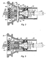
- the servomotor 10 of the figure 1 essentially comprises a rigid casing 12 in which a front chamber 14 and a rear chamber 16 are separated from each other by a movable transverse partition 18 which carries an axial piston 20.
- the front chamber 14 is intended to be connected to a source of depression, while the rear chamber 16 is selectively placed in communication with the front chamber 14 in the absence of braking or with the surrounding atmosphere during braking.
- the axial piston 20 of the booster is interposed between a control rod 22 actuated by a brake pedal (not shown) and a push rod 24 which acts on a piston of a brake master cylinder (not shown) at its end. before.
- a return spring 26 mounted in the front chamber 14 constantly urges the piston 20 into its rear rest position shown in FIG. figure 1 .
- the rear part of the casing 12 forms an axial chimney 28 in which is housed a rear tubular cylindrical portion 30 of the piston 20.
- the control rod 22 extends axially in this tubular portion 30 and carries at its front end a plunger 32 slidably guided in an axial passage 34 of the piston 20.
- the annular rear portion 36 of the plunger 32 cooperates with an annular valve 38 of a 3-way valve which selectively allows, depending on the axial position of the control rod 22 in the rear tubular portion 30 of the piston 20, to connect the rear chamber 16 of the booster to the front chamber 14 or the surrounding atmosphere.
- the front part of the plunger 32 has an axial passage 40 in which is guided in sliding a probe 42 which extends forwardly and which passes through an axial orifice 44 of a radial front face 46 of the piston 20 to come into contact, in case of braking, with a reaction disk 48 of substantially incompressible material such as rubber or an elastomer for example, which is mounted in a bowl 50 of the rear end of the push rod 24.
- the rear end of the probe 42 carries a transverse pin 52 which extends through oblong slots 54 of the plunger 32 and 56 of the piston 20 and which defines a rest position or rearmost position of the plunger 32 and the probe 42 when this pin 52 is supported on a rear stop 58 secured to the piston 20.
- the pin 52 defines an extreme front position of the probe 42 relative to the piston 20 when it is brought into contact with the front end of the slots 56 of the piston.
- Axial immobilization means of the probe 42 relative to the plunger 32 are provided between the front end of the plunger 32 and the radial front face 46 of the piston and are arranged in a transverse housing 60 of the piston.
- These means comprise a flat key 62 having a central orifice traversed with a weak clearance by the feeler 42, a rear rib 64 support rocker on the front face of the plunger 32 and a front rib 66 support rocker on the wall before the housing 60.
- At least one return spring 68 is mounted in the housing 60 between the front wall thereof and the key 62 to tilt it on the rear rib 64 in the opposite direction of the needles of a shows to figures 1 and 2 .
- another return spring 70 is mounted around the probe 42 and permanently urges the key 62 towards the front end of the plunger 32.
- the key 62 When the key 62 is in an oblique position as shown in figures 1 and 2 , it blocks the forward sliding of the plunger 32 on the probe 42. When this key is substantially perpendicular to the axis of the servomotor, it can be moved in translation on the probe 42 and then allows a forward movement of the plunger 32 with respect to probe 42.
- the front face of the probe 42 is moved away from the reaction disk 48 by a distance corresponding to the jump represented at S on the curve of the figure 4 which is the variation curve of the output pressure Pmc of the master cylinder as a function of the force Fe applied to the brake pedal.
- this curve comprises a first dead-ride retrofit phase a, a second phase which corresponds to the jump S, for which the pressure increases at the output of the master cylinder without the effort of Fe input increases, a third phase of assistance by the servomotor and a fourth phase b corresponding to the saturation of the servomotor.
- the servomotor shown in Figures 1 to 3 works as follows:
- control rod 22 and the plunger 32 are moved forward at the same speed as the piston 20 and the probe 42 remains locked relative to the plunger 32 by the key 62 occupying an oblique position as shown in FIG. figures 1 and 2 .
- the curve representing the variation of the output pressure Pmc of the master cylinder as a function of the input force Fe is that represented in solid lines in FIG. figure 4 .
- the control rod 22 and the plunger 32 are moved forward more rapidly than the piston 20, so that the plunger 32 pushes the key 62 forwards.
- the plunger 32 pushes the key 62 forwards.
- it tilts in the direction of clockwise and takes a substantially vertical position relative to the axis of the servomotor, which allows the plunger 32 slide forwardly relative to the probe 42. This results in a reduction in the total length of the assembly formed by the plunger 32 and the probe 42.
- the control rod 22 and the plunger 32 are moved forward by driving the probe 42 blocked by the key 62 which is supported on the plunger. This corresponds to an increase in the jump from S to S 'on the curve of the figure 4 , and the output pressure Pmc of the master cylinder varies according to the input force Fe as represented by the dashed curve.
- the assistance provided by the servomotor which is greater in this case than in the previous case for the same input effort, therefore promotes emergency braking.
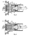
- the variant embodiment of the figure 5 and 6 differs from the achievement of Figures 1 to 3 essentially by the relative immobilization means of the plunger and the probe.
- the plunger 32 'mounted at the front end of the control rod 22 is received and guided in a blind axial passage of the probe 42' a front portion is guided in axial translation in a cylindrical passage 44 of the front face 46 of the piston 20, so as to bear against the reaction disk 48 mounted in the bowl 50 at the end of the push rod 24.
- a return spring 74 is mounted between the front face 46 of the piston and the front face of the probe 42 'to urge it permanently towards the rear.
- a transverse pin 52 is mounted in oblong slots of the plunger 32 ', the probe 42' and the piston 20 to define a rest position of the plunger 32 'and the probe 42', shown in the drawings.
- the relative axial immobilization means of the probe and the plunger are of the ramp or wedge type and comprise, as can be seen better in FIG. figure 7 , a series of conical rollers 76 which surround the plunger 32 'and which are housed inside the rear part of the probe 42', between a cylindrical surface 78 with a circular section of the plunger 32 'and an internal frustoconical surface 80 of the probe 42 '.
- the rollers 76 are oriented with their large base towards the rear and their small base towards the front and are held axially between two rings 82 and 84 threaded on the plunger 32 '.
- the assembly is urged continuously forward by a return spring 86 mounted between the rear ring 84 and a shoulder of the cylindrical surface of the plunger 32 '.
- the front ring 82 is thus held in abutment on the transverse pin 52.
- the control rod 22 and the plunger 32 ' are moved forward faster than the piston 20 of the booster and drive with them the probe 42' until it comes in abutment with the pin 52 itself bearing on the piston 20.
- the plunger 32 ' can thus advance more or less with respect to the probe 42', depending on its speed of displacement, which lengthens more or less the total length of the plunger-feeler assembly. If then the driver slightly relaxes the force exerted on the brake pedal, the probe 42 ', the plunger 32' and the control rod 22 move slightly backwards, the probe 42 'being locked in position on the plunger 32 by the tapered rollers 76.
Landscapes
- Engineering & Computer Science (AREA)
- Transportation (AREA)
- Mechanical Engineering (AREA)
- Braking Systems And Boosters (AREA)
- Braking Arrangements (AREA)
Claims (14)
- Pneumatischer Servomotor zur Bremsunterstützung, insbesondere für ein Kraftfahrzeug, mit einem axialen Kolben (20), der zwischen einer Schubstange (24) und einem am Ende einer Steuerstange (22) angebrachten Tauchkolben (32, 32') angeordnet ist, und mit Mitteln zur Unterstützung einer Schnellbremsung, die einen Taster (42, 42'), der am Tauchkolben vorgesehen ist und in Bezug auf diesen axial gleitend beweglich ist, und Mittel zur axialen Blockierung des Tasters (42, 42') umfassen, wobei die Blockierungsmittel dazu geeignet sind, in der Ruhestellung und bei einer Bremsung, wenn die Verlagerungsgeschwindigkeit der Steuerstange (22) und des Tauchkolbens (32, 32') unter einem Grenzwert liegt, den Taster (42, 42') in Bezug auf den Tauchkolben (32, 32') zu blockieren und bei einer Schnellbremsung, wenn die Verlagerungsgeschwindigkeit der Steuerstange und des Tauchkolbens über dem Grenzwert liegt, das Gleiten des Tauchkolbens (32, 32') in Bezug auf den Taster mehr oder weniger in Richtung der Verkürzung oder Verlängerung der axialen Länge der Tauchkolben-Taster-Baugruppe zu erlauben, wobei der Taster (42, 42') mit dem Kolben (20) zusammenwirkende Mittel (52) aufweist, um eine Ruhestellung des Tasters zu definieren, dadurch gekennzeichnet, dass die vorgenannten Mittel, die eine Ruhestellung des Tasters definieren, einen in einer Queröffnung des Tasters angebrachten Stift (52) aufweisen.
- Servomotor nach Anspruch 1, dadurch gekennzeichnet, dass die Enden des Stifts (52) in Langlöcher (56) eines zylindrischen Abschnitts des Kolbens (20) aufgenommen sind, wobei diese Löcher eine maximale axiale Verlagerung des Tasters in Bezug auf den Kolben begrenzen.
- Servomotor nach Anspruch 1 oder 2, dadurch gekennzeichnet, dass der Stift (52) mindestens ein Langloch (54) durchquert, das im Tauchkolben (32, 32') ausgebildet ist und eine Ruhestellung des Tauchkolbens in Bezug auf den Kolben (20) definiert.
- Servomotor nach Anspruch 3, dadurch gekennzeichnet, dass der Taster (42) in einem zylindrischen axialen Durchgang (40) des Tauchkolbens (32) aufgenommen und gleitend geführt.
- Servomotor nach einem der vorhergehenden Ansprüche, dadurch gekennzeichnet, dass der Tauchkolben (32) in einem zylindrischen axialen Durchgang (34) des Kolbens (20) geführt ist, der schubstangenseitig eine radiale Wand (46) aufweist, die mit einer axialen Öffnung (44) zum Durchführen des Tasters (42) ausgebildet ist.
- Servomotor nach einem der vorhergehenden Ansprüche, dadurch gekennzeichnet, dass die Blockierungsmittel eine Kipptaste (62) aufweisen, die in einer Queraufnahme (60) des Kolbens (20) angebracht ist und eine Öffnung aufweist, die von dem Taster (42) mit Spiel durchquert wird, sowie elastische Rückstellmittel (70), die die Taste konstant in Anlage an den Tauchkolben (32) beaufschlagen.
- Servomotor nach Anspruch 6, dadurch gekennzeichnet, dass die Taste (62) bei einer Schnellbremsung von dem Tauchkolben (32) zwischen einer Stellung zur Blockierung des Tasters (42) und einer Stellung zur Anlage am Kolben (20) des Servomotors bewegt werden kann, in welcher sie den Taster freigibt und ein Gleiten des Tauchkolbens (32) am Taster in Richtung der Schubstange (24) gestattet.
- Servomotor nach einem der Ansprüche 1 bis 3, dadurch gekennzeichnet, dass der Tauchkolben (32') in einem axialen Durchgang des Tasters (42') aufgenommen und gleitend geführt ist, der selbst in einem axialen Durchgang (44) des Kolbens (20) des Servomotors aufgenommen und geführt ist.
- Servomotor nach Anspruch 8, dadurch gekennzeichnet, dass die Blockierungsmittel Mittel mit einer Rampe oder einem Keil umfassen, die zwischen einer zylindrischen Fläche (78) des Tauchkolbens (32') und einer kegelstumpfartigen Innenfläche (81) des Tasters (42') angebracht sind.
- Servomotor nach Anspruch 8 oder 9, dadurch gekennzeichnet, dass die Blockierungsmittel mehrere kegelförmige Rollen (76) umfassen, die kronenartig um die zylindrische Fläche (78) des Tauchkolbens (32') verteilt und axial durch zwei Ringe (82, 84) gehalten sind, die auf den Tauchkolben (32') aufgeschoben sind.
- Servomotor nach einem der Ansprüche 8 bis 10, dadurch gekennzeichnet, dass die Blockierungsmittel durch elastische Rückstellmittel (86), die sich an einem Absatz des Tauchkolbens (32') abstützen, axial in Richtung der Schubstange (24) beaufschlagt werden.
- Servomotor nach Anspruch 11, dadurch gekennzeichnet, dass die Blockierungsmittel durch die elastischen Rückstellmittel (86) in Anlage an den Stift (52) gebracht werden, der in Querlöcher des Tauchkolbens (32'), des Tasters (42') und des Kolbens (20) eingreift.
- Servomotor nach Anspruch 12, dadurch gekennzeichnet, dass der Stift (52), der auf der Seite der Steuerstange (22) an einem Ende der Löcher des Kolbens (20) anliegt, eine Ruhestellung des Tauchkolbens (32') und des Tasters (42') definiert.
- Servomotor nach einem der Ansprüche 8 bis 13, dadurch gekennzeichnet, dass der Taster (42') durch elastische Rückstellmittel (74) axial in eine zur Schubstange (24) entgegengesetzte Richtung beaufschlagt wird.
Applications Claiming Priority (2)
| Application Number | Priority Date | Filing Date | Title |
|---|---|---|---|
| FR0216464A FR2848966B1 (fr) | 2002-12-20 | 2002-12-20 | Servomoteur d'assistance pneumatique au freinage, en particulier pour vehicule automobile |
| FR0216464 | 2002-12-20 |
Publications (2)
| Publication Number | Publication Date |
|---|---|
| EP1431152A1 EP1431152A1 (de) | 2004-06-23 |
| EP1431152B1 true EP1431152B1 (de) | 2010-12-01 |
Family
ID=32339006
Family Applications (1)
| Application Number | Title | Priority Date | Filing Date |
|---|---|---|---|
| EP03028932A Expired - Lifetime EP1431152B1 (de) | 2002-12-20 | 2003-12-17 | Pneumatischer Bremskraftverstärker, insbesondere für Kraftfahrzeuge |
Country Status (6)
| Country | Link |
|---|---|
| US (1) | US6988778B2 (de) |
| EP (1) | EP1431152B1 (de) |
| JP (1) | JP2004203380A (de) |
| AT (1) | ATE490139T1 (de) |
| DE (1) | DE60335168D1 (de) |
| FR (1) | FR2848966B1 (de) |
Families Citing this family (2)
| Publication number | Priority date | Publication date | Assignee | Title |
|---|---|---|---|---|
| KR101486231B1 (ko) * | 2008-08-22 | 2015-01-26 | 주식회사 만도 | 차량용 브레이크 부스터 |
| FR3040956B1 (fr) * | 2015-09-14 | 2017-10-06 | Bosch Gmbh Robert | Systeme d'assistance de freinage a moteur electrique |
Family Cites Families (7)
| Publication number | Priority date | Publication date | Assignee | Title |
|---|---|---|---|---|
| ES2197643T3 (es) * | 1998-05-15 | 2004-01-01 | CONTINENTAL TEVES AG & CO. OHG | Servofreno con funcion de frenado de panico. |
| DE19831961A1 (de) * | 1998-07-16 | 2000-01-20 | Continental Teves Ag & Co Ohg | Bremskraftverstärker mit Panikbremsfunktion |
| DE19831962A1 (de) * | 1998-07-16 | 2000-01-20 | Continental Teves Ag & Co Ohg | Bremskraftverstärker mit Panikbremsfunktion |
| FR2807986B1 (fr) * | 2000-04-21 | 2002-09-06 | Bosch Sist De Frenado Sl | Servomoteur comportant une douille de blocage formant palpeur |
| FR2809066B1 (fr) * | 2000-05-22 | 2002-08-09 | Bosch Sist De Frenado Sl | Servomoteur comportant un embrayage unidirectionnel expansible |
| JP2002337681A (ja) * | 2001-03-15 | 2002-11-27 | Bosch Automotive Systems Corp | ブレーキ倍力装置 |
| FR2825058B1 (fr) * | 2001-05-25 | 2003-09-19 | Bosch Sist De Frenado Sl | Servomoteur a deux sauts differencies fixe et variable |
-
2002
- 2002-12-20 FR FR0216464A patent/FR2848966B1/fr not_active Expired - Fee Related
-
2003
- 2003-12-17 DE DE60335168T patent/DE60335168D1/de not_active Expired - Lifetime
- 2003-12-17 AT AT03028932T patent/ATE490139T1/de not_active IP Right Cessation
- 2003-12-17 EP EP03028932A patent/EP1431152B1/de not_active Expired - Lifetime
- 2003-12-22 JP JP2003424607A patent/JP2004203380A/ja active Pending
-
2004
- 2004-01-09 US US10/759,709 patent/US6988778B2/en not_active Expired - Fee Related
Also Published As
| Publication number | Publication date |
|---|---|
| EP1431152A1 (de) | 2004-06-23 |
| US6988778B2 (en) | 2006-01-24 |
| JP2004203380A (ja) | 2004-07-22 |
| US20040140168A1 (en) | 2004-07-22 |
| FR2848966B1 (fr) | 2006-02-10 |
| DE60335168D1 (de) | 2011-01-13 |
| ATE490139T1 (de) | 2010-12-15 |
| FR2848966A1 (fr) | 2004-06-25 |
Similar Documents
| Publication | Publication Date | Title |
|---|---|---|
| EP0501843B1 (de) | Bremskraftverstärker mit einstellbarem Schwellenwert und Verfahren zum Regeln des Schwellenwertes | |
| EP1542891B1 (de) | Pneumatischer bremskraftverstärker | |
| EP0939713A1 (de) | Hilfskraftbremsvorrichtung mit variablem verstärkerverhältnis und verringerter hysterese | |
| EP1274617B1 (de) | Servomotor für eine notbremshilfe | |
| WO2001017831A1 (fr) | Servomoteur pneumatique a auto-assistance selective et controlee en effort | |
| EP1274618B1 (de) | Bremskraftverstärker mit einer einen taster bildenden blockierhülse | |
| EP1305197B1 (de) | Bremskraftverstärker für eine notbremshilfe mit schalldämmungsmittel | |
| EP1351849B1 (de) | Servomotor für notbremse mit mitteln zur verriegelung durch ein radiales hindernis | |
| EP1397279A1 (de) | Bremskraftverstärker mit zwei unterschiedlichen festen und veränderlichen schwellenwerten | |
| EP1431152A1 (de) | Pneumatischer Bremskraftverstärker, insbesondere für Kraftfahrzeuge | |
| FR2809066A1 (fr) | Servomoteur comportant un embrayage unidirectionnel expansible | |
| EP2178728B1 (de) | Bremskraftverstärker für ein kraftfahrzeugbremssystem | |
| EP1518770B1 (de) | Hauptzylinder mit erhöhertem Sicherheit | |
| EP1325853B1 (de) | Pneumatischer Bremsservo mit reduzierter Reaktion | |
| EP0939715A1 (de) | Hilfskraftunterstütztes bremssystem mit verbesserter hydraulischer reaktion | |
| FR2864502A1 (fr) | Servomoteur pneumatique d'assistance au freinage en particulier pour vehicule automobile | |
| EP1057704A1 (de) | Verbesserter Bremsverstärker | |
| WO2002087943A2 (fr) | Dispositif de freinage a rattrapage de courses mortes, en particulier pour vehicule automobile | |
| FR2830499A1 (fr) | Servomoteur a cle de verrouillage stabilisee | |
| FR2848969A1 (fr) | Servomoteur d'assistance pneumatique au freinage pour vehicule automobile | |
| FR2855135A1 (fr) | Servomoteur d'assistance pneumatique au freinage | |
| FR2867137A1 (fr) | Servomoteur a saut variable par douille deverrouillable | |
| FR2922174A1 (fr) | Systeme de freinage d'urgence pour vehicule automobile. | |
| WO2002087945A1 (fr) | Servomoteur comportant un embrayage unidirectionnel a billes. | |
| FR2824032A1 (fr) | Maitre-cylindre, notamment maitre-cylindre tandem comportant des moyens de levee de clapet ameliores |
Legal Events
| Date | Code | Title | Description |
|---|---|---|---|
| PUAI | Public reference made under article 153(3) epc to a published international application that has entered the european phase |
Free format text: ORIGINAL CODE: 0009012 |
|
| AK | Designated contracting states |
Kind code of ref document: A1 Designated state(s): AT BE BG CH CY CZ DE DK EE ES FI FR GB GR HU IE IT LI LU MC NL PT RO SE SI SK TR |
|
| AX | Request for extension of the european patent |
Extension state: AL LT LV MK |
|
| AKX | Designation fees paid | ||
| 17P | Request for examination filed |
Effective date: 20041223 |
|
| RBV | Designated contracting states (corrected) |
Designated state(s): AT BE BG CH CY CZ DE DK EE ES FI FR GB GR HU IE IT LI LU MC NL PT RO SE SI SK TR |
|
| REG | Reference to a national code |
Ref country code: DE Ref legal event code: 8566 |
|
| GRAP | Despatch of communication of intention to grant a patent |
Free format text: ORIGINAL CODE: EPIDOSNIGR1 |
|
| RAP1 | Party data changed (applicant data changed or rights of an application transferred) |
Owner name: BOSCH SISTEMAS DE FRENADO, S.L. |
|
| GRAS | Grant fee paid |
Free format text: ORIGINAL CODE: EPIDOSNIGR3 |
|
| GRAA | (expected) grant |
Free format text: ORIGINAL CODE: 0009210 |
|
| AK | Designated contracting states |
Kind code of ref document: B1 Designated state(s): AT BE BG CH CY CZ DE DK EE ES FI FR GB GR HU IE IT LI LU MC NL PT RO SE SI SK TR |
|
| REG | Reference to a national code |
Ref country code: GB Ref legal event code: FG4D Free format text: NOT ENGLISH |
|
| REG | Reference to a national code |
Ref country code: CH Ref legal event code: EP |
|
| REG | Reference to a national code |
Ref country code: IE Ref legal event code: FG4D |
|
| REF | Corresponds to: |
Ref document number: 60335168 Country of ref document: DE Date of ref document: 20110113 Kind code of ref document: P |
|
| REG | Reference to a national code |
Ref country code: NL Ref legal event code: VDEP Effective date: 20101201 |
|
| PG25 | Lapsed in a contracting state [announced via postgrant information from national office to epo] |
Ref country code: SE Free format text: LAPSE BECAUSE OF FAILURE TO SUBMIT A TRANSLATION OF THE DESCRIPTION OR TO PAY THE FEE WITHIN THE PRESCRIBED TIME-LIMIT Effective date: 20101201 Ref country code: SI Free format text: LAPSE BECAUSE OF FAILURE TO SUBMIT A TRANSLATION OF THE DESCRIPTION OR TO PAY THE FEE WITHIN THE PRESCRIBED TIME-LIMIT Effective date: 20101201 Ref country code: AT Free format text: LAPSE BECAUSE OF FAILURE TO SUBMIT A TRANSLATION OF THE DESCRIPTION OR TO PAY THE FEE WITHIN THE PRESCRIBED TIME-LIMIT Effective date: 20101201 Ref country code: FI Free format text: LAPSE BECAUSE OF FAILURE TO SUBMIT A TRANSLATION OF THE DESCRIPTION OR TO PAY THE FEE WITHIN THE PRESCRIBED TIME-LIMIT Effective date: 20101201 Ref country code: CY Free format text: LAPSE BECAUSE OF FAILURE TO SUBMIT A TRANSLATION OF THE DESCRIPTION OR TO PAY THE FEE WITHIN THE PRESCRIBED TIME-LIMIT Effective date: 20101201 Ref country code: BG Free format text: LAPSE BECAUSE OF FAILURE TO SUBMIT A TRANSLATION OF THE DESCRIPTION OR TO PAY THE FEE WITHIN THE PRESCRIBED TIME-LIMIT Effective date: 20110301 Ref country code: NL Free format text: LAPSE BECAUSE OF FAILURE TO SUBMIT A TRANSLATION OF THE DESCRIPTION OR TO PAY THE FEE WITHIN THE PRESCRIBED TIME-LIMIT Effective date: 20101201 |
|
| REG | Reference to a national code |
Ref country code: IE Ref legal event code: FD4D |
|
| BERE | Be: lapsed |
Owner name: BOSCH SISTEMAS DE FRENADO, S.L. Effective date: 20101231 |
|
| PG25 | Lapsed in a contracting state [announced via postgrant information from national office to epo] |
Ref country code: GR Free format text: LAPSE BECAUSE OF FAILURE TO SUBMIT A TRANSLATION OF THE DESCRIPTION OR TO PAY THE FEE WITHIN THE PRESCRIBED TIME-LIMIT Effective date: 20110302 |
|
| PG25 | Lapsed in a contracting state [announced via postgrant information from national office to epo] |
Ref country code: PT Free format text: LAPSE BECAUSE OF FAILURE TO SUBMIT A TRANSLATION OF THE DESCRIPTION OR TO PAY THE FEE WITHIN THE PRESCRIBED TIME-LIMIT Effective date: 20110401 Ref country code: CZ Free format text: LAPSE BECAUSE OF FAILURE TO SUBMIT A TRANSLATION OF THE DESCRIPTION OR TO PAY THE FEE WITHIN THE PRESCRIBED TIME-LIMIT Effective date: 20101201 Ref country code: ES Free format text: LAPSE BECAUSE OF FAILURE TO SUBMIT A TRANSLATION OF THE DESCRIPTION OR TO PAY THE FEE WITHIN THE PRESCRIBED TIME-LIMIT Effective date: 20110312 Ref country code: IE Free format text: LAPSE BECAUSE OF FAILURE TO SUBMIT A TRANSLATION OF THE DESCRIPTION OR TO PAY THE FEE WITHIN THE PRESCRIBED TIME-LIMIT Effective date: 20101201 Ref country code: MC Free format text: LAPSE BECAUSE OF NON-PAYMENT OF DUE FEES Effective date: 20101231 Ref country code: EE Free format text: LAPSE BECAUSE OF FAILURE TO SUBMIT A TRANSLATION OF THE DESCRIPTION OR TO PAY THE FEE WITHIN THE PRESCRIBED TIME-LIMIT Effective date: 20101201 |
|
| REG | Reference to a national code |
Ref country code: CH Ref legal event code: PL |
|
| PG25 | Lapsed in a contracting state [announced via postgrant information from national office to epo] |
Ref country code: RO Free format text: LAPSE BECAUSE OF FAILURE TO SUBMIT A TRANSLATION OF THE DESCRIPTION OR TO PAY THE FEE WITHIN THE PRESCRIBED TIME-LIMIT Effective date: 20101201 Ref country code: SK Free format text: LAPSE BECAUSE OF FAILURE TO SUBMIT A TRANSLATION OF THE DESCRIPTION OR TO PAY THE FEE WITHIN THE PRESCRIBED TIME-LIMIT Effective date: 20101201 |
|
| PG25 | Lapsed in a contracting state [announced via postgrant information from national office to epo] |
Ref country code: BE Free format text: LAPSE BECAUSE OF NON-PAYMENT OF DUE FEES Effective date: 20101231 |
|
| PLBE | No opposition filed within time limit |
Free format text: ORIGINAL CODE: 0009261 |
|
| STAA | Information on the status of an ep patent application or granted ep patent |
Free format text: STATUS: NO OPPOSITION FILED WITHIN TIME LIMIT |
|
| PG25 | Lapsed in a contracting state [announced via postgrant information from national office to epo] |
Ref country code: LI Free format text: LAPSE BECAUSE OF NON-PAYMENT OF DUE FEES Effective date: 20101231 Ref country code: CH Free format text: LAPSE BECAUSE OF NON-PAYMENT OF DUE FEES Effective date: 20101231 Ref country code: DK Free format text: LAPSE BECAUSE OF FAILURE TO SUBMIT A TRANSLATION OF THE DESCRIPTION OR TO PAY THE FEE WITHIN THE PRESCRIBED TIME-LIMIT Effective date: 20101201 |
|
| 26N | No opposition filed |
Effective date: 20110902 |
|
| REG | Reference to a national code |
Ref country code: DE Ref legal event code: R097 Ref document number: 60335168 Country of ref document: DE Effective date: 20110902 |
|
| PG25 | Lapsed in a contracting state [announced via postgrant information from national office to epo] |
Ref country code: IT Free format text: LAPSE BECAUSE OF FAILURE TO SUBMIT A TRANSLATION OF THE DESCRIPTION OR TO PAY THE FEE WITHIN THE PRESCRIBED TIME-LIMIT Effective date: 20101201 |
|
| PG25 | Lapsed in a contracting state [announced via postgrant information from national office to epo] |
Ref country code: LU Free format text: LAPSE BECAUSE OF NON-PAYMENT OF DUE FEES Effective date: 20101217 Ref country code: HU Free format text: LAPSE BECAUSE OF FAILURE TO SUBMIT A TRANSLATION OF THE DESCRIPTION OR TO PAY THE FEE WITHIN THE PRESCRIBED TIME-LIMIT Effective date: 20110602 |
|
| PG25 | Lapsed in a contracting state [announced via postgrant information from national office to epo] |
Ref country code: TR Free format text: LAPSE BECAUSE OF FAILURE TO SUBMIT A TRANSLATION OF THE DESCRIPTION OR TO PAY THE FEE WITHIN THE PRESCRIBED TIME-LIMIT Effective date: 20101201 |
|
| REG | Reference to a national code |
Ref country code: FR Ref legal event code: PLFP Year of fee payment: 13 |
|
| PGFP | Annual fee paid to national office [announced via postgrant information from national office to epo] |
Ref country code: DE Payment date: 20160224 Year of fee payment: 13 |
|
| REG | Reference to a national code |
Ref country code: FR Ref legal event code: PLFP Year of fee payment: 14 |
|
| PGFP | Annual fee paid to national office [announced via postgrant information from national office to epo] |
Ref country code: GB Payment date: 20161222 Year of fee payment: 14 |
|
| PGFP | Annual fee paid to national office [announced via postgrant information from national office to epo] |
Ref country code: FR Payment date: 20161221 Year of fee payment: 14 |
|
| REG | Reference to a national code |
Ref country code: DE Ref legal event code: R119 Ref document number: 60335168 Country of ref document: DE |
|
| PG25 | Lapsed in a contracting state [announced via postgrant information from national office to epo] |
Ref country code: DE Free format text: LAPSE BECAUSE OF NON-PAYMENT OF DUE FEES Effective date: 20170701 |
|
| GBPC | Gb: european patent ceased through non-payment of renewal fee |
Effective date: 20171217 |
|
| REG | Reference to a national code |
Ref country code: FR Ref legal event code: ST Effective date: 20180831 |
|
| PG25 | Lapsed in a contracting state [announced via postgrant information from national office to epo] |
Ref country code: FR Free format text: LAPSE BECAUSE OF NON-PAYMENT OF DUE FEES Effective date: 20180102 |
|
| PG25 | Lapsed in a contracting state [announced via postgrant information from national office to epo] |
Ref country code: GB Free format text: LAPSE BECAUSE OF NON-PAYMENT OF DUE FEES Effective date: 20171217 |