EP1741943A2 - Lageranordnung zur Kraftübertragung einer Windenergieanlage - Google Patents
Lageranordnung zur Kraftübertragung einer Windenergieanlage Download PDFInfo
- Publication number
- EP1741943A2 EP1741943A2 EP06291085A EP06291085A EP1741943A2 EP 1741943 A2 EP1741943 A2 EP 1741943A2 EP 06291085 A EP06291085 A EP 06291085A EP 06291085 A EP06291085 A EP 06291085A EP 1741943 A2 EP1741943 A2 EP 1741943A2
- Authority
- EP
- European Patent Office
- Prior art keywords
- axis
- rings
- blade
- piece
- ring
- Prior art date
- Legal status (The legal status is an assumption and is not a legal conclusion. Google has not performed a legal analysis and makes no representation as to the accuracy of the status listed.)
- Granted
Links
Images



Classifications
-
- F—MECHANICAL ENGINEERING; LIGHTING; HEATING; WEAPONS; BLASTING
- F16—ENGINEERING ELEMENTS AND UNITS; GENERAL MEASURES FOR PRODUCING AND MAINTAINING EFFECTIVE FUNCTIONING OF MACHINES OR INSTALLATIONS; THERMAL INSULATION IN GENERAL
- F16C—SHAFTS; FLEXIBLE SHAFTS; ELEMENTS OR CRANKSHAFT MECHANISMS; ROTARY BODIES OTHER THAN GEARING ELEMENTS; BEARINGS
- F16C19/00—Bearings with rolling contact, for exclusively rotary movement
- F16C19/02—Bearings with rolling contact, for exclusively rotary movement with bearing balls essentially of the same size in one or more circular rows
- F16C19/14—Bearings with rolling contact, for exclusively rotary movement with bearing balls essentially of the same size in one or more circular rows for both radial and axial load
- F16C19/18—Bearings with rolling contact, for exclusively rotary movement with bearing balls essentially of the same size in one or more circular rows for both radial and axial load with two or more rows of balls
-
- F—MECHANICAL ENGINEERING; LIGHTING; HEATING; WEAPONS; BLASTING
- F16—ENGINEERING ELEMENTS AND UNITS; GENERAL MEASURES FOR PRODUCING AND MAINTAINING EFFECTIVE FUNCTIONING OF MACHINES OR INSTALLATIONS; THERMAL INSULATION IN GENERAL
- F16C—SHAFTS; FLEXIBLE SHAFTS; ELEMENTS OR CRANKSHAFT MECHANISMS; ROTARY BODIES OTHER THAN GEARING ELEMENTS; BEARINGS
- F16C19/00—Bearings with rolling contact, for exclusively rotary movement
- F16C19/50—Other types of ball or roller bearings
- F16C19/505—Other types of ball or roller bearings with the diameter of the rolling elements of one row differing from the diameter of those of another row
-
- F—MECHANICAL ENGINEERING; LIGHTING; HEATING; WEAPONS; BLASTING
- F16—ENGINEERING ELEMENTS AND UNITS; GENERAL MEASURES FOR PRODUCING AND MAINTAINING EFFECTIVE FUNCTIONING OF MACHINES OR INSTALLATIONS; THERMAL INSULATION IN GENERAL
- F16C—SHAFTS; FLEXIBLE SHAFTS; ELEMENTS OR CRANKSHAFT MECHANISMS; ROTARY BODIES OTHER THAN GEARING ELEMENTS; BEARINGS
- F16C35/00—Rigid support of bearing units; Housings, e.g. caps, covers
- F16C35/04—Rigid support of bearing units; Housings, e.g. caps, covers in the case of ball or roller bearings
- F16C35/06—Mounting or dismounting of ball or roller bearings; Fixing them onto shaft or in housing
-
- F—MECHANICAL ENGINEERING; LIGHTING; HEATING; WEAPONS; BLASTING
- F16—ENGINEERING ELEMENTS AND UNITS; GENERAL MEASURES FOR PRODUCING AND MAINTAINING EFFECTIVE FUNCTIONING OF MACHINES OR INSTALLATIONS; THERMAL INSULATION IN GENERAL
- F16C—SHAFTS; FLEXIBLE SHAFTS; ELEMENTS OR CRANKSHAFT MECHANISMS; ROTARY BODIES OTHER THAN GEARING ELEMENTS; BEARINGS
- F16C2300/00—Application independent of particular apparatuses
- F16C2300/10—Application independent of particular apparatuses related to size
- F16C2300/14—Large applications, e.g. bearings having an inner diameter exceeding 500 mm
-
- F—MECHANICAL ENGINEERING; LIGHTING; HEATING; WEAPONS; BLASTING
- F16—ENGINEERING ELEMENTS AND UNITS; GENERAL MEASURES FOR PRODUCING AND MAINTAINING EFFECTIVE FUNCTIONING OF MACHINES OR INSTALLATIONS; THERMAL INSULATION IN GENERAL
- F16C—SHAFTS; FLEXIBLE SHAFTS; ELEMENTS OR CRANKSHAFT MECHANISMS; ROTARY BODIES OTHER THAN GEARING ELEMENTS; BEARINGS
- F16C2360/00—Engines or pumps
- F16C2360/31—Wind motors
-
- Y—GENERAL TAGGING OF NEW TECHNOLOGICAL DEVELOPMENTS; GENERAL TAGGING OF CROSS-SECTIONAL TECHNOLOGIES SPANNING OVER SEVERAL SECTIONS OF THE IPC; TECHNICAL SUBJECTS COVERED BY FORMER USPC CROSS-REFERENCE ART COLLECTIONS [XRACs] AND DIGESTS
- Y02—TECHNOLOGIES OR APPLICATIONS FOR MITIGATION OR ADAPTATION AGAINST CLIMATE CHANGE
- Y02B—CLIMATE CHANGE MITIGATION TECHNOLOGIES RELATED TO BUILDINGS, e.g. HOUSING, HOUSE APPLIANCES OR RELATED END-USER APPLICATIONS
- Y02B10/00—Integration of renewable energy sources in buildings
- Y02B10/30—Wind power
-
- Y—GENERAL TAGGING OF NEW TECHNOLOGICAL DEVELOPMENTS; GENERAL TAGGING OF CROSS-SECTIONAL TECHNOLOGIES SPANNING OVER SEVERAL SECTIONS OF THE IPC; TECHNICAL SUBJECTS COVERED BY FORMER USPC CROSS-REFERENCE ART COLLECTIONS [XRACs] AND DIGESTS
- Y02—TECHNOLOGIES OR APPLICATIONS FOR MITIGATION OR ADAPTATION AGAINST CLIMATE CHANGE
- Y02E—REDUCTION OF GREENHOUSE GAS [GHG] EMISSIONS, RELATED TO ENERGY GENERATION, TRANSMISSION OR DISTRIBUTION
- Y02E10/00—Energy generation through renewable energy sources
- Y02E10/70—Wind energy
- Y02E10/72—Wind turbines with rotation axis in wind direction
Definitions
- the invention relates to a particular assembly for a wind turbine and relates to the use in particular of a pivoting servomotor bearing for a blade of a rotor hub of a wind turbine.
- the bearings undergo great efforts.
- the blades of these wind turbines they undergo significant efforts not only in the axis of the / each blade (axial forces), but also radially to the axis of the blade and the rotor hub (radial or centrifugal forces).
- the blades can rotate about ten degrees about their axis of elongation to promote the performance according to the direction of the wind.
- an object of the invention is to improve these points compared to existing solutions by promoting the mechanical strength of the bearings, the fixing conditions and costs.
- a proposed solution consists in that, on the aforementioned assembly bearing / rotor hub / wind turbine blade, the aforementioned connecting portion extends, parallel to said radial direction to the axis of the blade, next to the first and second rings, which are secured together on this connecting portion by first and second fixing means, respectively.
- a set especially for a wind turbine, comprising a pivot bearing interposed between a first and a second parts.
- the preceding part of connection is replaced by a connecting piece interposed between the second part and the first and second rings and extending, in a direction radial to the axis of said second part, next to these first and second rings with which it is linked.
- the second piece "replaces" the blade of the wind turbine, the first rotor.
- the second piece (blade) will be exclusively attached to the third ring (intermediate) and will not be fixed directly to the first and second end rings.
- Blade side / second piece via said connecting piece or hub side / first piece (via said connecting portion), there is systematically indirect attachment to them of the first and second rings, with at least one passage of common effort to two rings.
- the rotor hub having an axis parallel to that of the blade, along a section parallel to this axis of the hub, said connecting portion defines an extension T integrated in the rotor hub and whose bar receives the fasteners between this connecting portion and the first and second bearing rings, respectively.
- the bearing further comprises an element or a retaining part which is mechanically connected to the connecting piece or to the rotor hub, being retained at least radially at least once.
- the axis of the blade by one or the other, and which, in a direction radial to this blade axis, borders an outer peripheral surface of that of said rings which is radially furthest from the axis of the blade , to counter a radial force tending to separate between them at least said rings and / or to deflect the ring radially furthest from the axis of the blade, during the rotation of the blade.
- the first ring which is radially furthest from the axis of the blade, may radially have a greater thickness towards its end closest to the blade than towards its end nearest the rotor hub, this ring having consequently an outer peripheral surface having a generator not parallel or not continuously parallel to the axis of the blade.
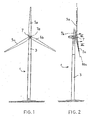
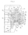
- FIGS. 1 and 2 show a wind turbine 1 comprising a mast 3 at the top of which three blades 5a, 5b, 5c rotate around the horizontal axis 7a of a central hub 7.
- the hub 7 is mounted itself around a vertical axis 7b with respect to the mast 3, to orient itself better vis-à-vis the wind.
- Each blade, and in particular the blade 5c of Figure 2 can rotate a few degrees or tens of degrees around its axis of elongation 50c, relative to the rotor hub 7, so as to take the best wind.
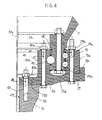
- Figure 3 found in 50c the axis of the blade 5c and 7 the rotor hub.
- each blade such as the blade 5c, generates in particular significant radial forces, as well as high bending moments.
- the bearing 9 illustrated in FIG. 3 is a double row bearing of bearings 11a, 11b.
- the three rings are concentric with respect to the axis 50c and therefore all extend in a general plane 21 radial to the axis 50c.
- the intermediate ring 19 is fixed on the rotor hub 7, while the outer and inner rings 13 13 are fixed to the rotor blade 5c, via a connecting piece 23.
- the connecting piece 23 ensures, here vis-à-vis the blade 5c, the direct attachment to this blade of the inner ring 15, via the fixing means 25, while the attachment to the blade of the outer ring 13 is only indirect, since it is fixed on the connecting piece 23 by the fastening means 27.
- the first ring 13 is radially beyond the blade.
- its axial fastening means 27, here bolts open on the outside, at two opposite axial ends of the ring, and are here easily accessible, either by the clamping head 27a, or by the nut 27b .
- this volume 31 communicates axially with the hollow interior volume 500c of the blade shown here, via the intermediate internal volumes successively of the inner ring 15 and of the connecting piece 23 interposed parallel to the axis 50c between the rings 13, 15 and the blade, against which these rings come to bear.
- the threaded rod 25 is screwed into the body of the blade 5c.
- the rod 25 passes through the second ring 15 and the connecting piece 23.
- the fasteners are here axial, which is preferable, and these fasteners provide at least a common passage of efforts to the two rings 13, 15, which are thus fixed with the connecting piece 23 at two different radial distances from the axis of the blade.
- first ring 13 is fixed directly on the connecting piece 23, and not on the blade, while the second ring 15 is, with and / or through the connecting piece 23, thus ensuring by a connection with the blade through which will pass the efforts exerted on both the first and second rings.
- the first ring 19 and its fastening means 29, which open at one end in the volume 31 (nut 29b) and at the other end (hexagon head 29a) in a chamber radially limited by the respectively outer and inner walls, cylindrical two rings 15, 13 and, axially, at one end by the flat wall of the ring 19 where the head 29a is supported, and at the other end by a concave surface 230 of the connecting piece 23.
- the tightening end of the bolt 29, which opens at 33, is locked in rotation by retention protrusions 35 fixed to the ring 19 or to the connecting piece 23.
- the ring 19 is fixed on the hub 7 and its clamping, here parallel to the axis 50c, can take place from the internal volume 31.
- the retaining portion 231 is intimately connected to the connecting piece 23 to which is integrated and that it extends in the manner of a shoulder on which radially bears, in the zone 130, the peripheral surface 13a of the ring 13.
- connection by other means, such as fixing means (screwing, welding 7-8), so that the integrated part 231 could form a physically distinct element, although fixedly bound and rigidly to the connecting piece 23.
- the rotor hub 7 has a radial protrusion 71 provided with a shoulder 700, bearing in radial abutment against said outer surface 13a, but on the side of the opposite end of the ring 13, that is to say towards its end closest to the hub 7, axially.
- this shoulder 700 could even belong to a connecting piece 800 (ghosting figure 3) interposed between the hub 7 and the ring 19 and that the means 29 would pass through to be fixed in the hub.
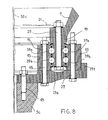
- FIG. 4 shows the same constituent elements and the same arrangements as in FIG. 3, except for the attachment to the blade 5c of the connecting piece 23 (here marked 23a) and for the rolling balls which There are now three of them, although a four-bearing arrangement as in Figure 3, in two rows of two, may be quite appropriate.
- a solid portion 233 provided with axial orifices (parallel to the axis 50c) 41 located at a radial distance d4 from the axis 50c less than all the aforesaid distances d1, d2, d3 shown in FIG. 3.
- These orifices are each traversed by one of several fourth fixing means 43 which fix, alone, the connecting piece 23a (which of course has the shape of a ring like the part 23), and this directly to the blade 5c, while both the first outer ring 13 that the second ring 15 are each fixed only to this connecting piece 23a, at two different radial distances, here respectively d1 and d5.
- the fastening means here identical, corresponding to the bolts such as 27 and 45, open on one side by their screwed head screw and, on the other, by the threaded end of their rod provided with the nuts 27b and 45b, on the outside, or inside the hub 7, in the volume 31 for the threaded rod corresponding to the bolt 45.
- the third bearing 47 is again a spherical bearing, but it is larger in volume than other bearings 37a, 37b.
- the third bearing 47 is located between the two series of bearings 37a, 37b of the other line, following an orthogonal projection on the axis 50c.
- the connecting piece 23a is thus fixed on this blade, while at distances d1 and d5, different, the first and third rings 13, 15 are individually fixed on this connecting piece. 23a.
- part 23 and the rings 13, 15 are not threaded.
- FIG. 5 there is a rotor hub, here marked 70, and the wind turbine blade 5c which then has a slightly larger diameter than in the case of Figures 3 and 4.
- the bearing always comprises a first outer ring (radially to the axis 50c) 130, an inner ring 150 and an intermediate ring 190.
- FIG. 7 moreover, these fasteners have been illustrated: at each pitch P, there is found for each ring a fastening either to the blade or the hub, and to the same diameter, as was found in FIG. 3 at the same diameter d2 , and with this same pitch P, a fixing of the inner ring 15 to the blade and, by the same, a connection between the ring 15, the connecting piece 23 and the blade.
- the bearings are not shown.
- FIGS. 5 and 6 show a fixing of the intermediate ring 190 in the root of the blade 5c, while the two end rings 130, 150 are fixed directly on the hub 70, all here parallel to the axis of elongation 50c of the blade 5c.
- the fastening means (27, 49 respectively) of these rings are directly attached to the connecting portion 51 intimately connected to the rotor hub 70 and extending, in the direction 21 already mentioned, radially to the axis of the blade, up to the two end rings 130 and 150, with a locally concave surface 510, in front of the fastening means 53 through which the intermediate ring 190 is fixed in the root of the blade 5c.
- the fastening means 53 may be identical to the means 25 of FIG. 3 and comprise here threaded rods of which the hexagonal head 55 is housed in the closed chamber extending facing the surface 510, at the end of FIG. image of the chamber 33 of FIG.
- FIG. 6 shows the same assembly, except that instead of the two rows with two series of bearings each 37a, 37b and 39a, 39b of FIG. 5, there is the double row 39a, 39b with the smaller diameter d7, while at the upper diameter d8 we find the series of spherical bearings of larger diameter 47 already presented.
- the series of bearings 47 could be of diameter d7 and the two series of double spherical bearings of smaller diameter with diameter d8, as shown in FIG. 4.
- the outer ring 130 farthest from the axis 50c radially has a greater thickness, such as e1, towards its end 130a closest to the blade, while towards its end 130b closest to the hub of rotor 70 this thickness decreases (see thickness e2 Figure 6, with e2 less than e1).
- the ring 130 has an outer peripheral surface 130c having a generatrix 130d non-parallel, or non-continuous parallel to the axis 50c.
- the outer peripheral surface 130c here corresponds to a wall of bias with respect to the axis 50c. It could be a step or shoulder near end 130a and increasing the thickness of e2 to e1.
- this additional radial thickness will be at least 20%.
- the connecting portion 51 is integrated integrally with the rotor hub 70 that it extends, in section, in the manner of a T whose shaft extends axially the body of the rotor hub and whose the bar receives on one side (51a) the tight fixing of the fixing means 27 and, on the other, 51b, the tight fixing of the fixing means 49 which thus open on one side in the hollow interior volume 310 of the rotor hub 70 and, at the opposite axial end, in front of the inner volume 500d of the blade 5c whose inner diameter d9 is slightly greater than that d10 of the blade of FIG. 3, which was still greater than the diameter d11 of the blade of FIG. 4.
- the inner volume 500d communicates with the internal volume 310 by the internal volume of the intermediate ring 190, those of the inner ring 150 and the end forming the connecting portion 51.
- FIG. 3 could also fix the inner ring 15 only to the connecting piece 23 and the outer ring 13 to a larger blade. diameter, through this connecting piece, making thus pass through it the efforts of the ring 15 and its connection to the blade.
Landscapes
- Engineering & Computer Science (AREA)
- General Engineering & Computer Science (AREA)
- Mechanical Engineering (AREA)
- Wind Motors (AREA)
- Structures Of Non-Positive Displacement Pumps (AREA)
- Sliding-Contact Bearings (AREA)
- Supercharger (AREA)
- Turbine Rotor Nozzle Sealing (AREA)
Applications Claiming Priority (1)
| Application Number | Priority Date | Filing Date | Title |
|---|---|---|---|
| FR0507110A FR2887943B1 (fr) | 2005-07-04 | 2005-07-04 | Palier d'eolienne a transmission d'efforts |
Publications (4)
| Publication Number | Publication Date |
|---|---|
| EP1741943A2 true EP1741943A2 (de) | 2007-01-10 |
| EP1741943A3 EP1741943A3 (de) | 2008-10-08 |
| EP1741943B1 EP1741943B1 (de) | 2011-11-16 |
| EP1741943B2 EP1741943B2 (de) | 2016-04-06 |
Family
ID=36190490
Family Applications (1)
| Application Number | Title | Priority Date | Filing Date |
|---|---|---|---|
| EP06291085.6A Active EP1741943B2 (de) | 2005-07-04 | 2006-06-30 | Lageranordnung zur Kraftübertragung einer Windenergieanlage |
Country Status (6)
| Country | Link |
|---|---|
| EP (1) | EP1741943B2 (de) |
| CN (2) | CN1924381B (de) |
| AT (1) | ATE533951T1 (de) |
| DK (1) | DK1741943T4 (de) |
| ES (1) | ES2376473T5 (de) |
| FR (1) | FR2887943B1 (de) |
Cited By (6)
| Publication number | Priority date | Publication date | Assignee | Title |
|---|---|---|---|---|
| EP2372149A1 (de) * | 2010-03-29 | 2011-10-05 | Vestas Wind Systems A/s | Eine Windkraftanlage und ein Pitch-Lager für eine Windkraftanlage |
| EP2372146A1 (de) * | 2010-03-29 | 2011-10-05 | Vestas Wind Systems A/s | Windturbine und Walzlager für eine Windturbine |
| EP1907694B2 (de) † | 2005-07-08 | 2016-01-20 | Vestas Wind Systems A/S | Windturbine, nabe für eine windturbine und verwendung davon |
| EP3384157A4 (de) * | 2016-12-30 | 2019-07-17 | Beijing Goldwind Science & Creation Windpower Equipment Co., Ltd. | Blattlager, schaufel, laufrad einer windturbine und verbindungsverfahren für eine windturbine |
| DE202022101187U1 (de) | 2022-03-03 | 2022-03-10 | Thyssenkrupp AG | Wälzlager mit verlängerter Lebensdauer |
| US11415171B2 (en) * | 2017-12-06 | 2022-08-16 | thyssenkrupp rothe erde Germany GmbH | Rolling bearing arrangement |
Families Citing this family (5)
| Publication number | Priority date | Publication date | Assignee | Title |
|---|---|---|---|---|
| US8459872B2 (en) * | 2008-10-10 | 2013-06-11 | General Electric Company | Bearing with alternative load path for extreme loads |
| DE102009049769A1 (de) * | 2009-10-16 | 2011-04-21 | Suzlon Energy Gmbh | Lageranordnung für eine Windturbine |
| EP3563057B1 (de) * | 2016-12-30 | 2024-08-07 | General Electric Renovables España, S.L. | Naben-wellen-adapter für eine rotoranordnung einer windturbine und zugehörige montageverfahren |
| CN109424636B (zh) * | 2017-08-29 | 2020-12-29 | 中国航发商用航空发动机有限责任公司 | 多转子用轴承及航空发动机 |
| CN110529495A (zh) * | 2019-08-30 | 2019-12-03 | 江苏如非轴承科技有限公司 | 一种高转速加强型回转轴承结构 |
Citations (1)
| Publication number | Priority date | Publication date | Assignee | Title |
|---|---|---|---|---|
| EP1266137A1 (de) | 2000-03-10 | 2002-12-18 | Aloys Wobben | Lagerung eines verstellbaren rotorblatts einer windenergieanlage |
Family Cites Families (7)
| Publication number | Priority date | Publication date | Assignee | Title |
|---|---|---|---|---|
| DE1622154U (de) * | 1951-01-29 | 1951-04-12 | Artur Moenkedick | Massstabanordnung an zeichengeraeten. |
| DE1622154A1 (de) * | 1968-01-19 | 1970-12-03 | Vni Kt I | Waelzlager fuer Aufhaengeachsen von feinmechanischen Geraeten,insbesondere von Kreiseln |
| DE3413286C1 (de) * | 1984-04-07 | 1986-01-09 | Hoesch Ag, 4600 Dortmund | Mittenfreies Grosswaelzlager |
| DE19962978C1 (de) * | 1999-12-24 | 2001-08-30 | Aloys Wobben | Windenergieanlage mit einem turmgestützten Maschinenkopf |
| DE10141667A1 (de) * | 2001-08-25 | 2003-03-13 | Aloys Wobben | Vorrichtung zum Verdrehen von zwei Bauteilen gegeneinander |
| DE10256855A1 (de) * | 2002-12-05 | 2004-06-17 | Ab Skf | Verfahren zur Montage eines zweireihigen Kegelrollenlagers |
| DE10316005A1 (de) * | 2003-04-07 | 2004-10-21 | Ab Skf | Verfahren zur Einstellung des Spiels oder der Vorspannung eines Lagers |
-
2005
- 2005-07-04 FR FR0507110A patent/FR2887943B1/fr not_active Expired - Lifetime
-
2006
- 2006-06-30 AT AT06291085T patent/ATE533951T1/de active
- 2006-06-30 DK DK06291085.6T patent/DK1741943T4/en active
- 2006-06-30 ES ES06291085.6T patent/ES2376473T5/es active Active
- 2006-06-30 EP EP06291085.6A patent/EP1741943B2/de active Active
- 2006-07-04 CN CN2006101371292A patent/CN1924381B/zh active Active
- 2006-07-04 CN CN2009101297118A patent/CN101526106B/zh active Active
Patent Citations (1)
| Publication number | Priority date | Publication date | Assignee | Title |
|---|---|---|---|---|
| EP1266137A1 (de) | 2000-03-10 | 2002-12-18 | Aloys Wobben | Lagerung eines verstellbaren rotorblatts einer windenergieanlage |
Cited By (9)
| Publication number | Priority date | Publication date | Assignee | Title |
|---|---|---|---|---|
| EP1907694B2 (de) † | 2005-07-08 | 2016-01-20 | Vestas Wind Systems A/S | Windturbine, nabe für eine windturbine und verwendung davon |
| EP2372149A1 (de) * | 2010-03-29 | 2011-10-05 | Vestas Wind Systems A/s | Eine Windkraftanlage und ein Pitch-Lager für eine Windkraftanlage |
| EP2372146A1 (de) * | 2010-03-29 | 2011-10-05 | Vestas Wind Systems A/s | Windturbine und Walzlager für eine Windturbine |
| US8109729B2 (en) | 2010-03-29 | 2012-02-07 | Vestas Wind Systems A/S | Wind turbine and a pitch bearing for a wind turbine |
| US8876477B2 (en) | 2010-03-29 | 2014-11-04 | Vestas Wind Systems A/S | Wind turbine and a pitch bearing for a wind turbine |
| EP3384157A4 (de) * | 2016-12-30 | 2019-07-17 | Beijing Goldwind Science & Creation Windpower Equipment Co., Ltd. | Blattlager, schaufel, laufrad einer windturbine und verbindungsverfahren für eine windturbine |
| US10801468B2 (en) | 2016-12-30 | 2020-10-13 | Beijing Goldwing Science & Creation Windpower Equipment Co., Ltd. | Pitch bearing, blade, impeller of wind turbine and connecting method for wind turbine |
| US11415171B2 (en) * | 2017-12-06 | 2022-08-16 | thyssenkrupp rothe erde Germany GmbH | Rolling bearing arrangement |
| DE202022101187U1 (de) | 2022-03-03 | 2022-03-10 | Thyssenkrupp AG | Wälzlager mit verlängerter Lebensdauer |
Also Published As
| Publication number | Publication date |
|---|---|
| ES2376473T3 (es) | 2012-03-14 |
| CN1924381B (zh) | 2010-05-12 |
| ES2376473T5 (es) | 2016-09-05 |
| FR2887943B1 (fr) | 2008-08-22 |
| HK1135163A1 (zh) | 2010-05-28 |
| CN1924381A (zh) | 2007-03-07 |
| EP1741943B1 (de) | 2011-11-16 |
| FR2887943A1 (fr) | 2007-01-05 |
| CN101526106B (zh) | 2012-04-25 |
| EP1741943B2 (de) | 2016-04-06 |
| CN101526106A (zh) | 2009-09-09 |
| EP1741943A3 (de) | 2008-10-08 |
| DK1741943T4 (en) | 2016-07-18 |
| ATE533951T1 (de) | 2011-12-15 |
| DK1741943T3 (da) | 2011-12-19 |
Similar Documents
| Publication | Publication Date | Title |
|---|---|---|
| EP1741940B1 (de) | Tonnenlager | |
| EP2503164B2 (de) | Lager mit drei Reihen und mehr von Wälzkörpern | |
| EP1741943B1 (de) | Lageranordnung zur Kraftübertragung einer Windenergieanlage | |
| EP1910708B1 (de) | Epizyklisches antriebssystem mit flexpins | |
| EP2452050B2 (de) | Ölabscheideranordnung | |
| EP0604299A1 (de) | Blatt-Nabe geschichtete Verbindungsvorrichtung, Rotorblatt und damit ausgerüsteter Rotor | |
| EP3732384B1 (de) | Planetenträger für ein epizyklisches untersetzungsgetriebe | |
| EP2722559A2 (de) | Wälzlager und Windkraftanlage damit | |
| FR2842271A1 (fr) | Boite de transmissiion de puissance basculante a transfert de charge par le carter | |
| WO2013034697A1 (fr) | Entraînement de broyeur vertical à plusieurs entraînements principaux | |
| FR2936767A1 (fr) | Palier a roulement, notamment pour colonne de direction. | |
| EP1865206A2 (de) | Keilriementriebwerk | |
| CA2982070C (fr) | Faisceau torsible pour pale, un ensemble de faisceaux torsibles, un rotor et un aeronef | |
| FR2887934A1 (fr) | Palier a bagues retenues radialement | |
| FR2961281A1 (fr) | Dispositif de butee de debrayage comprenant une bague d'usure. | |
| EP3756994B1 (de) | Vorschubpropeller, der mit auswechselbaren schraubenblättern ausgestattet ist, und montageverfahren für auswechselbare schraubenblätter auf einem vorschubpropeller | |
| EP1548233B1 (de) | Befestigungsvorrichtung für Statorschaufel, sowie Leitschaufelstufe eines Verdichters mit einer solchen Vorrichtung | |
| EP2148105B1 (de) | Monoblock-Fahrradkurbelgarnitur | |
| EP3874163B1 (de) | Windturbinenturmabschnitt, windturbinenturm und montageverfahren | |
| EP4008929B1 (de) | Planetenbaugruppe, planetensatz mit einer solchen baugruppe und getriebe | |
| FR2949858A1 (fr) | Dispositif et procede d'equilibrage | |
| EP1939409B1 (de) | System zur Verbindung von zwei in etwa röhrenförmigen Elementen, Gehäuse, das ein solches System umfasst, und Verwendung dieses Systems | |
| FR2922974A1 (fr) | Mecanisme d'entrainement par courroie et son procede de fabrication. | |
| CA3074502A1 (fr) | Train epicycloidal d'engrenage, boite de transmission de puissance, aeronef, et procede | |
| FR3068748A1 (fr) | Train epicycloidal d'engrenages, boite de transmission de puissance, aeronef et procede applique par ledit train epicycloidal |
Legal Events
| Date | Code | Title | Description |
|---|---|---|---|
| PUAI | Public reference made under article 153(3) epc to a published international application that has entered the european phase |
Free format text: ORIGINAL CODE: 0009012 |
|
| AK | Designated contracting states |
Kind code of ref document: A2 Designated state(s): AT BE BG CH CY CZ DE DK EE ES FI FR GB GR HU IE IS IT LI LT LU LV MC NL PL PT RO SE SI SK TR |
|
| AX | Request for extension of the european patent |
Extension state: AL BA HR MK YU |
|
| PUAL | Search report despatched |
Free format text: ORIGINAL CODE: 0009013 |
|
| AK | Designated contracting states |
Kind code of ref document: A3 Designated state(s): AT BE BG CH CY CZ DE DK EE ES FI FR GB GR HU IE IS IT LI LT LU LV MC NL PL PT RO SE SI SK TR |
|
| AX | Request for extension of the european patent |
Extension state: AL BA HR MK RS |
|
| RIC1 | Information provided on ipc code assigned before grant |
Ipc: F03D 1/06 20060101ALI20080829BHEP Ipc: F16C 19/55 20060101AFI20061204BHEP Ipc: F03D 11/00 20060101ALI20080829BHEP |
|
| 17P | Request for examination filed |
Effective date: 20090331 |
|
| AKX | Designation fees paid |
Designated state(s): AT BE BG CH CY CZ DE DK EE ES FI FR GB GR HU IE IS IT LI LT LU LV MC NL PL PT RO SE SI SK TR |
|
| GRAP | Despatch of communication of intention to grant a patent |
Free format text: ORIGINAL CODE: EPIDOSNIGR1 |
|
| GRAS | Grant fee paid |
Free format text: ORIGINAL CODE: EPIDOSNIGR3 |
|
| GRAA | (expected) grant |
Free format text: ORIGINAL CODE: 0009210 |
|
| AK | Designated contracting states |
Kind code of ref document: B1 Designated state(s): AT BE BG CH CY CZ DE DK EE ES FI FR GB GR HU IE IS IT LI LT LU LV MC NL PL PT RO SE SI SK TR |
|
| REG | Reference to a national code |
Ref country code: GB Ref legal event code: FG4D Free format text: NOT ENGLISH |
|
| REG | Reference to a national code |
Ref country code: CH Ref legal event code: EP |
|
| REG | Reference to a national code |
Ref country code: IE Ref legal event code: FG4D Free format text: LANGUAGE OF EP DOCUMENT: FRENCH |
|
| REG | Reference to a national code |
Ref country code: DK Ref legal event code: T3 |
|
| REG | Reference to a national code |
Ref country code: DE Ref legal event code: R096 Ref document number: 602006025826 Country of ref document: DE Effective date: 20120112 |
|
| REG | Reference to a national code |
Ref country code: NL Ref legal event code: VDEP Effective date: 20111116 |
|
| REG | Reference to a national code |
Ref country code: ES Ref legal event code: FG2A Ref document number: 2376473 Country of ref document: ES Kind code of ref document: T3 Effective date: 20120314 |
|
| LTIE | Lt: invalidation of european patent or patent extension |
Effective date: 20111116 |
|
| PG25 | Lapsed in a contracting state [announced via postgrant information from national office to epo] |
Ref country code: LT Free format text: LAPSE BECAUSE OF FAILURE TO SUBMIT A TRANSLATION OF THE DESCRIPTION OR TO PAY THE FEE WITHIN THE PRESCRIBED TIME-LIMIT Effective date: 20111116 Ref country code: IS Free format text: LAPSE BECAUSE OF FAILURE TO SUBMIT A TRANSLATION OF THE DESCRIPTION OR TO PAY THE FEE WITHIN THE PRESCRIBED TIME-LIMIT Effective date: 20120316 |
|
| PG25 | Lapsed in a contracting state [announced via postgrant information from national office to epo] |
Ref country code: NL Free format text: LAPSE BECAUSE OF FAILURE TO SUBMIT A TRANSLATION OF THE DESCRIPTION OR TO PAY THE FEE WITHIN THE PRESCRIBED TIME-LIMIT Effective date: 20111116 Ref country code: LV Free format text: LAPSE BECAUSE OF FAILURE TO SUBMIT A TRANSLATION OF THE DESCRIPTION OR TO PAY THE FEE WITHIN THE PRESCRIBED TIME-LIMIT Effective date: 20111116 Ref country code: PT Free format text: LAPSE BECAUSE OF FAILURE TO SUBMIT A TRANSLATION OF THE DESCRIPTION OR TO PAY THE FEE WITHIN THE PRESCRIBED TIME-LIMIT Effective date: 20120316 Ref country code: PL Free format text: LAPSE BECAUSE OF FAILURE TO SUBMIT A TRANSLATION OF THE DESCRIPTION OR TO PAY THE FEE WITHIN THE PRESCRIBED TIME-LIMIT Effective date: 20111116 Ref country code: SE Free format text: LAPSE BECAUSE OF FAILURE TO SUBMIT A TRANSLATION OF THE DESCRIPTION OR TO PAY THE FEE WITHIN THE PRESCRIBED TIME-LIMIT Effective date: 20111116 Ref country code: SI Free format text: LAPSE BECAUSE OF FAILURE TO SUBMIT A TRANSLATION OF THE DESCRIPTION OR TO PAY THE FEE WITHIN THE PRESCRIBED TIME-LIMIT Effective date: 20111116 Ref country code: GR Free format text: LAPSE BECAUSE OF FAILURE TO SUBMIT A TRANSLATION OF THE DESCRIPTION OR TO PAY THE FEE WITHIN THE PRESCRIBED TIME-LIMIT Effective date: 20120217 |
|
| REG | Reference to a national code |
Ref country code: IE Ref legal event code: FD4D |
|
| PG25 | Lapsed in a contracting state [announced via postgrant information from national office to epo] |
Ref country code: CY Free format text: LAPSE BECAUSE OF FAILURE TO SUBMIT A TRANSLATION OF THE DESCRIPTION OR TO PAY THE FEE WITHIN THE PRESCRIBED TIME-LIMIT Effective date: 20111116 |
|
| PG25 | Lapsed in a contracting state [announced via postgrant information from national office to epo] |
Ref country code: SK Free format text: LAPSE BECAUSE OF FAILURE TO SUBMIT A TRANSLATION OF THE DESCRIPTION OR TO PAY THE FEE WITHIN THE PRESCRIBED TIME-LIMIT Effective date: 20111116 Ref country code: EE Free format text: LAPSE BECAUSE OF FAILURE TO SUBMIT A TRANSLATION OF THE DESCRIPTION OR TO PAY THE FEE WITHIN THE PRESCRIBED TIME-LIMIT Effective date: 20111116 Ref country code: IE Free format text: LAPSE BECAUSE OF FAILURE TO SUBMIT A TRANSLATION OF THE DESCRIPTION OR TO PAY THE FEE WITHIN THE PRESCRIBED TIME-LIMIT Effective date: 20111116 Ref country code: BG Free format text: LAPSE BECAUSE OF FAILURE TO SUBMIT A TRANSLATION OF THE DESCRIPTION OR TO PAY THE FEE WITHIN THE PRESCRIBED TIME-LIMIT Effective date: 20120216 Ref country code: CZ Free format text: LAPSE BECAUSE OF FAILURE TO SUBMIT A TRANSLATION OF THE DESCRIPTION OR TO PAY THE FEE WITHIN THE PRESCRIBED TIME-LIMIT Effective date: 20111116 |
|
| PLBI | Opposition filed |
Free format text: ORIGINAL CODE: 0009260 |
|
| PG25 | Lapsed in a contracting state [announced via postgrant information from national office to epo] |
Ref country code: RO Free format text: LAPSE BECAUSE OF FAILURE TO SUBMIT A TRANSLATION OF THE DESCRIPTION OR TO PAY THE FEE WITHIN THE PRESCRIBED TIME-LIMIT Effective date: 20111116 |
|
| REG | Reference to a national code |
Ref country code: AT Ref legal event code: MK05 Ref document number: 533951 Country of ref document: AT Kind code of ref document: T Effective date: 20111116 |
|
| PLAX | Notice of opposition and request to file observation + time limit sent |
Free format text: ORIGINAL CODE: EPIDOSNOBS2 |
|
| 26 | Opposition filed |
Opponent name: SEIBIG, HILDEGARD Effective date: 20120814 |
|
| REG | Reference to a national code |
Ref country code: DE Ref legal event code: R026 Ref document number: 602006025826 Country of ref document: DE Effective date: 20120814 |
|
| BERE | Be: lapsed |
Owner name: DEFONTAINE Effective date: 20120630 |
|
| PLAF | Information modified related to communication of a notice of opposition and request to file observations + time limit |
Free format text: ORIGINAL CODE: EPIDOSCOBS2 |
|
| PG25 | Lapsed in a contracting state [announced via postgrant information from national office to epo] |
Ref country code: AT Free format text: LAPSE BECAUSE OF FAILURE TO SUBMIT A TRANSLATION OF THE DESCRIPTION OR TO PAY THE FEE WITHIN THE PRESCRIBED TIME-LIMIT Effective date: 20111116 Ref country code: MC Free format text: LAPSE BECAUSE OF NON-PAYMENT OF DUE FEES Effective date: 20120630 |
|
| REG | Reference to a national code |
Ref country code: CH Ref legal event code: PL |
|
| REG | Reference to a national code |
Ref country code: CH Ref legal event code: PL |
|
| PLBB | Reply of patent proprietor to notice(s) of opposition received |
Free format text: ORIGINAL CODE: EPIDOSNOBS3 |
|
| PG25 | Lapsed in a contracting state [announced via postgrant information from national office to epo] |
Ref country code: LI Free format text: LAPSE BECAUSE OF NON-PAYMENT OF DUE FEES Effective date: 20120630 Ref country code: BE Free format text: LAPSE BECAUSE OF NON-PAYMENT OF DUE FEES Effective date: 20120630 Ref country code: CH Free format text: LAPSE BECAUSE OF NON-PAYMENT OF DUE FEES Effective date: 20120630 |
|
| PG25 | Lapsed in a contracting state [announced via postgrant information from national office to epo] |
Ref country code: FI Free format text: LAPSE BECAUSE OF FAILURE TO SUBMIT A TRANSLATION OF THE DESCRIPTION OR TO PAY THE FEE WITHIN THE PRESCRIBED TIME-LIMIT Effective date: 20111116 |
|
| PG25 | Lapsed in a contracting state [announced via postgrant information from national office to epo] |
Ref country code: TR Free format text: LAPSE BECAUSE OF FAILURE TO SUBMIT A TRANSLATION OF THE DESCRIPTION OR TO PAY THE FEE WITHIN THE PRESCRIBED TIME-LIMIT Effective date: 20111116 |
|
| PG25 | Lapsed in a contracting state [announced via postgrant information from national office to epo] |
Ref country code: LU Free format text: LAPSE BECAUSE OF NON-PAYMENT OF DUE FEES Effective date: 20120630 |
|
| PG25 | Lapsed in a contracting state [announced via postgrant information from national office to epo] |
Ref country code: HU Free format text: LAPSE BECAUSE OF FAILURE TO SUBMIT A TRANSLATION OF THE DESCRIPTION OR TO PAY THE FEE WITHIN THE PRESCRIBED TIME-LIMIT Effective date: 20060630 |
|
| REG | Reference to a national code |
Ref country code: FR Ref legal event code: PLFP Year of fee payment: 11 |
|
| PUAH | Patent maintained in amended form |
Free format text: ORIGINAL CODE: 0009272 |
|
| STAA | Information on the status of an ep patent application or granted ep patent |
Free format text: STATUS: PATENT MAINTAINED AS AMENDED |
|
| 27A | Patent maintained in amended form |
Effective date: 20160406 |
|
| AK | Designated contracting states |
Kind code of ref document: B2 Designated state(s): AT BE BG CH CY CZ DE DK EE ES FI FR GB GR HU IE IS IT LI LT LU LV MC NL PL PT RO SE SI SK TR |
|
| REG | Reference to a national code |
Ref country code: DE Ref legal event code: R102 Ref document number: 602006025826 Country of ref document: DE |
|
| RIC2 | Information provided on ipc code assigned after grant |
Ipc: F16C 19/55 20060101AFI20160229BHEP Ipc: F03D 1/06 20060101ALI20160229BHEP Ipc: F03D 80/00 20160101ALI20160229BHEP |
|
| REG | Reference to a national code |
Ref country code: DK Ref legal event code: T4 Effective date: 20160713 |
|
| REG | Reference to a national code |
Ref country code: ES Ref legal event code: DC2A Ref document number: 2376473 Country of ref document: ES Kind code of ref document: T5 Effective date: 20160905 |
|
| REG | Reference to a national code |
Ref country code: FR Ref legal event code: PLFP Year of fee payment: 12 |
|
| REG | Reference to a national code |
Ref country code: FR Ref legal event code: PLFP Year of fee payment: 13 |
|
| PGFP | Annual fee paid to national office [announced via postgrant information from national office to epo] |
Ref country code: DE Payment date: 20250618 Year of fee payment: 20 |
|
| PGFP | Annual fee paid to national office [announced via postgrant information from national office to epo] |
Ref country code: GB Payment date: 20250625 Year of fee payment: 20 Ref country code: DK Payment date: 20250618 Year of fee payment: 20 |
|
| PGFP | Annual fee paid to national office [announced via postgrant information from national office to epo] |
Ref country code: FR Payment date: 20250623 Year of fee payment: 20 |
|
| PGFP | Annual fee paid to national office [announced via postgrant information from national office to epo] |
Ref country code: ES Payment date: 20250718 Year of fee payment: 20 |
|
| PGFP | Annual fee paid to national office [announced via postgrant information from national office to epo] |
Ref country code: IT Payment date: 20250630 Year of fee payment: 20 |