EP1741961A2 - Méthode de changement de vitesse de transmission - Google Patents
Méthode de changement de vitesse de transmission Download PDFInfo
- Publication number
- EP1741961A2 EP1741961A2 EP06116722A EP06116722A EP1741961A2 EP 1741961 A2 EP1741961 A2 EP 1741961A2 EP 06116722 A EP06116722 A EP 06116722A EP 06116722 A EP06116722 A EP 06116722A EP 1741961 A2 EP1741961 A2 EP 1741961A2
- Authority
- EP
- European Patent Office
- Prior art keywords
- pressure
- clutch
- slip
- going
- coming
- Prior art date
- Legal status (The legal status is an assumption and is not a legal conclusion. Google has not performed a legal analysis and makes no representation as to the accuracy of the status listed.)
- Granted
Links
- 230000005540 biological transmission Effects 0.000 title claims abstract description 60
- 238000000034 method Methods 0.000 title claims abstract description 39
- 230000003247 decreasing effect Effects 0.000 claims abstract description 7
- 230000006870 function Effects 0.000 description 9
- 238000010586 diagram Methods 0.000 description 7
- 230000008859 change Effects 0.000 description 4
- 238000001514 detection method Methods 0.000 description 4
- 230000007704 transition Effects 0.000 description 4
- 238000012935 Averaging Methods 0.000 description 3
- 238000004891 communication Methods 0.000 description 3
- 238000004519 manufacturing process Methods 0.000 description 3
- 230000007423 decrease Effects 0.000 description 2
- 230000001934 delay Effects 0.000 description 2
- 238000012986 modification Methods 0.000 description 2
- 230000004048 modification Effects 0.000 description 2
- 230000008569 process Effects 0.000 description 2
- 238000012545 processing Methods 0.000 description 2
- 238000006243 chemical reaction Methods 0.000 description 1
- 238000011217 control strategy Methods 0.000 description 1
- 230000007812 deficiency Effects 0.000 description 1
- 230000001419 dependent effect Effects 0.000 description 1
- 230000000694 effects Effects 0.000 description 1
- 238000001914 filtration Methods 0.000 description 1
- 239000000446 fuel Substances 0.000 description 1
- 230000009191 jumping Effects 0.000 description 1
Images




Classifications
-
- F—MECHANICAL ENGINEERING; LIGHTING; HEATING; WEAPONS; BLASTING
- F16—ENGINEERING ELEMENTS AND UNITS; GENERAL MEASURES FOR PRODUCING AND MAINTAINING EFFECTIVE FUNCTIONING OF MACHINES OR INSTALLATIONS; THERMAL INSULATION IN GENERAL
- F16H—GEARING
- F16H61/00—Control functions within control units of change-speed- or reversing-gearings for conveying rotary motion ; Control of exclusively fluid gearing, friction gearing, gearings with endless flexible members or other particular types of gearing
- F16H61/04—Smoothing ratio shift
- F16H61/06—Smoothing ratio shift by controlling rate of change of fluid pressure
- F16H61/061—Smoothing ratio shift by controlling rate of change of fluid pressure using electric control means
-
- F—MECHANICAL ENGINEERING; LIGHTING; HEATING; WEAPONS; BLASTING
- F16—ENGINEERING ELEMENTS AND UNITS; GENERAL MEASURES FOR PRODUCING AND MAINTAINING EFFECTIVE FUNCTIONING OF MACHINES OR INSTALLATIONS; THERMAL INSULATION IN GENERAL
- F16H—GEARING
- F16H59/00—Control inputs to control units of change-speed- or reversing-gearings for conveying rotary motion
- F16H59/36—Inputs being a function of speed
- F16H59/46—Inputs being a function of speed dependent on a comparison between speeds
- F16H2059/465—Detecting slip, e.g. clutch slip ratio
-
- F—MECHANICAL ENGINEERING; LIGHTING; HEATING; WEAPONS; BLASTING
- F16—ENGINEERING ELEMENTS AND UNITS; GENERAL MEASURES FOR PRODUCING AND MAINTAINING EFFECTIVE FUNCTIONING OF MACHINES OR INSTALLATIONS; THERMAL INSULATION IN GENERAL
- F16H—GEARING
- F16H61/00—Control functions within control units of change-speed- or reversing-gearings for conveying rotary motion ; Control of exclusively fluid gearing, friction gearing, gearings with endless flexible members or other particular types of gearing
- F16H61/04—Smoothing ratio shift
- F16H61/06—Smoothing ratio shift by controlling rate of change of fluid pressure
- F16H61/061—Smoothing ratio shift by controlling rate of change of fluid pressure using electric control means
- F16H2061/062—Smoothing ratio shift by controlling rate of change of fluid pressure using electric control means for controlling filling of clutches or brake servos, e.g. fill time, fill level or pressure during filling
-
- F—MECHANICAL ENGINEERING; LIGHTING; HEATING; WEAPONS; BLASTING
- F16—ENGINEERING ELEMENTS AND UNITS; GENERAL MEASURES FOR PRODUCING AND MAINTAINING EFFECTIVE FUNCTIONING OF MACHINES OR INSTALLATIONS; THERMAL INSULATION IN GENERAL
- F16H—GEARING
- F16H61/00—Control functions within control units of change-speed- or reversing-gearings for conveying rotary motion ; Control of exclusively fluid gearing, friction gearing, gearings with endless flexible members or other particular types of gearing
- F16H61/04—Smoothing ratio shift
- F16H61/06—Smoothing ratio shift by controlling rate of change of fluid pressure
- F16H61/061—Smoothing ratio shift by controlling rate of change of fluid pressure using electric control means
- F16H2061/064—Smoothing ratio shift by controlling rate of change of fluid pressure using electric control means for calibration of pressure levels for friction members, e.g. by monitoring the speed change of transmission shafts
-
- F—MECHANICAL ENGINEERING; LIGHTING; HEATING; WEAPONS; BLASTING
- F16—ENGINEERING ELEMENTS AND UNITS; GENERAL MEASURES FOR PRODUCING AND MAINTAINING EFFECTIVE FUNCTIONING OF MACHINES OR INSTALLATIONS; THERMAL INSULATION IN GENERAL
- F16H—GEARING
- F16H2342/00—Calibrating
- F16H2342/04—Calibrating engagement of friction elements
-
- F—MECHANICAL ENGINEERING; LIGHTING; HEATING; WEAPONS; BLASTING
- F16—ENGINEERING ELEMENTS AND UNITS; GENERAL MEASURES FOR PRODUCING AND MAINTAINING EFFECTIVE FUNCTIONING OF MACHINES OR INSTALLATIONS; THERMAL INSULATION IN GENERAL
- F16H—GEARING
- F16H59/00—Control inputs to control units of change-speed- or reversing-gearings for conveying rotary motion
- F16H59/36—Inputs being a function of speed
- F16H59/46—Inputs being a function of speed dependent on a comparison between speeds
-
- F—MECHANICAL ENGINEERING; LIGHTING; HEATING; WEAPONS; BLASTING
- F16—ENGINEERING ELEMENTS AND UNITS; GENERAL MEASURES FOR PRODUCING AND MAINTAINING EFFECTIVE FUNCTIONING OF MACHINES OR INSTALLATIONS; THERMAL INSULATION IN GENERAL
- F16H—GEARING
- F16H61/00—Control functions within control units of change-speed- or reversing-gearings for conveying rotary motion ; Control of exclusively fluid gearing, friction gearing, gearings with endless flexible members or other particular types of gearing
- F16H61/68—Control functions within control units of change-speed- or reversing-gearings for conveying rotary motion ; Control of exclusively fluid gearing, friction gearing, gearings with endless flexible members or other particular types of gearing specially adapted for stepped gearings
- F16H61/684—Control functions within control units of change-speed- or reversing-gearings for conveying rotary motion ; Control of exclusively fluid gearing, friction gearing, gearings with endless flexible members or other particular types of gearing specially adapted for stepped gearings without interruption of drive
Definitions
- the present invention relates to a method of shifting a powershift transmission.
- the shift smoothness is normally controlled by engaging the on-coming clutches at low pressure. The amount of pressure necessary is dependent on the load being transmitted by the transmission to the drive wheels. If the engagement pressure is too low, the vehicle may lose speed during the shift. If the engagement pressure is too high, the shift will be very aggressive and harsh.
- Another disadvantage of this method is that the first detection of slip always results in the vehicle slowing down. During an upshift, it is not desirable to feel the vehicle first slow down before it finally speeds up.
- an object of this invention is to provide a method for smoothly shifting a powershift transmission which does not cause the vehicle to lose speed during the shift.
- a method for smoothly shifting a powershift transmission shall be provided which does not cause a harsh shift quality due to a misleading engine load signal.
- both the off-going and on-coming clutches are commanded to pressures that are a function of the engine load signal.
- the purpose of this step is to quickly get the off-going clutch to the pressure that is slightly higher than what it would be expected to start slipping at.
- the on-coming clutch is quickly brought up to a pressure that is slightly lower than what it would take to carry the engine load. From that starting point, the off-going clutch is ramped down in pressure while, simultaneously, the on-coming clutch is being ramped up.
- Speed sensors are used on the transmission input shaft, transmission output shaft, and an internal transmission component so that the system can determine when any of the clutches are slipping.
- Fig. 1 is a schematic block diagram of a transmission control system according to the present invention
- Fig. 2 is a schematic diagram of the transmission of Fig. 1;
- Fig. 3 is logic flow diagram illustrating an algorithm executed by the transmission controller of Fig. 1;
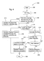
- Fig. 4 is logic flow diagram illustrating an algorithm represented by step 106 of Fig. 1;
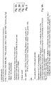
- Figs. 5A, 5B and 5C contain a pseudo code program listing of a subroutine performed by the algorithm represented by Fig. 4;
- Fig. 6 is a timing diagram of clutch pressure commands and engine throttle according to the present invention.
- Fig. 7 is a timing diagram of clutch pressure commands according to a prior art transmission control system.
- Fig. 1 is a schematic block diagram of a microprocessor-based transmission control system 10 to which the present invention is applicable.
- a vehicle power train includes an engine 12 which is controlled by electronic engine control unit 14, and which drives a power shift transmission (PST) 16 via input shaft 13.
- Transmission 16 has a countershaft 15, and an output shaft 18 which is connected to drive wheels (not shown).
- the PST 16 includes a set of pressure operated control elements or clutches 20 which are controlled by a corresponding set of solenoid operated proportional control valves 22.
- the transmission 16 may be a transmission such as described in US 5,011,465 .
- the valves 22 may be two-stage electro-hydraulic valves as described in US 4,741,364 .
- the PST 16 is controlled by a transmission control unit 24, an armrest control unit 26 which receives and interprets shift lever commands from shift command lever unit 28.
- Shift command lever unit 28 is preferably a conventional shift command lever unit used on production John Deere tractors, and includes a gearshift lever 29. Such a shift command lever unit is described in US 5,406,860 .
- a display unit 30 may display information relating to the system 10.
- the transmission control unit 24 and the armrest control unit 26 are preferably microprocessor-based electronic control units.
- Manual control is achieved via an operator-controlled gearshift command lever unit 28.
- Unit 28 provide signals representing the position of the lever 29 to the armrest control unit 26.
- the armrest control unit 26 sends gear command information to transmission control unit 24 via a vehicle communication bus 52.
- a clutch engagement sensor 32 and a clutch disengagement switch 34 provide signals representing the position of a clutch pedal 36.
- the engine control unit 14 receives signals from an engine speed sensor 38, as well as other sensors (not shown) which enable the engine control unit to transmit engine load information on the vehicle communication bus 52.
- the transmission controller 24 receives signals from an axle speed sensor 40, a counter-shaft speed sensor 42 which senses the speed of an intermediate shaft or counter-shaft 15 which is internal to the transmission 16, and a transmission oil temperature sensor 44.
- the transmission controller 24 sends wheel speed (calculated from the axle speed based on tire size), and oil temperature information to the display 30 via the vehicle communications bus 52.
- the intermediate shaft speed information is used only for control purposes and is not displayed under normal operating conditions.
- the transmission control unit 24 includes a commercially available microprocessor which supplies control signals to a set of valve drivers (not shown) which provide variable duty cycle pulse-width-modulated voltage control signals to the valves 22.
- the transmission control unit 24 generates control signals as a function of various sensed and operator determined inputs in order to achieve a desired pressure in the clutches and to thereby control the shifting of the transmission 16 in a desired manner.
- the transmission 16 includes various shafts, gears and clutches, including clutches AB, BC, CC, DC, C1, C2, C3, C4 and CR. For example, when a 5F to 4F (5 th gear forward to 4 th gear forward) range shift is performed clutch AB is disengaged while clutch BC is engaged, and clutch C4 is disengaged while clutch C1 is engaged.
- the transmission controller 24 executes a known production main loop algorithm (not shown) which controls the time varying hydraulic pressures which are applied to the various transmission clutch elements.
- the controller also executes an algorithm represented by Figs. 3 and 4.
- the conversion of the flow charts of Figs. 3 and 4 into a standard language for implementing the algorithm described by the flow chart in a digital computer or microprocessor, will be evident to one with ordinary skill in the art.
- Fig. 3 illustrates how this method is implemented by an algorithm 100 executed by the microcomputer-based transmission controller 24.
- This algorithm 100 is preferably executed at least once every ten milliseconds by a task manager type of real time operating system running in the transmission controller 24.
- the controller 24 Before the algorithm 100 is run, the controller 24 will have already determined or calculated 1) what shift is desired to be executed, and 2) an array of values which represent the current time into the shift for each clutch element.
- the algorithms 100 and 200 determine desired clutch pressure values. After the algorithms 100 and 200 are run, the main loop algorithm applies the desired pressures to the particular clutches involved in the shift being executed.
- the algorithm 100 begins at step 102.
- the algorithm is supplied with a pointer to a lookup table (not shown) containing known shift parameters for the particular shift being commanded, in this case, for example, a 5F to 4F range shift.
- the algorithm obtains an array of pre-determined shift time values for each clutch element.
- Step 108 represents a start of the loop for each transmission clutch element.
- the main clutch element loop which begins at step 108 is executed once for each transmission clutch element.
- Lookup Table Processing is performed at step 110.
- This processing uses the current time value for the clutch and the desired shift to set a lookup table pointer to the command step that should be executed for the transmission clutch element.
- Each command step contains the following three components. First, the time during the shift when this command step should be executed. This time could be an absolute time, or could be relative to some previous command step. Second, either a pressure command or a special instruction. Third, a slope. The slope entry is used for open-loop shifts that are not the subject of this patent application.
- Step 112 determines whether or not the lookup table pointer indicates that clutch slip logic should be performed for this transmission clutch element. If yes, then step 114 executes a clutch slip function or subroutine 200 which calculates a desired clutch pressure according to a subroutine or function described in more detail with respect to Fig. 4. If not, the algorithm proceeds to step 116 and the clutch pressures are determined in a known open loop manner as was done in a previous production transmission controller.
- the clutch slip subroutine 200 begins a step 202.
- the subroutine obtains engine speed data from sensor 38, engine load data from engine controller 14, shaft speed data from either sensor 40 or 42, and gear ratio data from a shaft speed vs. current gear lookup table (not shown).
- step 212 If it is the first time the subroutine 200 is being entered for this particular transmission clutch element for this particular shift, then the subroutine is directed to step 212, else to step 214.
- the empirically determined intercept b is made relative to the value of the calibrated fill pressure for the transmission clutch element by subtracting the product of the calibrated fill pressure and slope m.
- the equation developed from experimental data can be applied to all tractors to which the method or system described in this application applies.
- step 214 determines if the algorithm is in a fast ramp down phase.
- Each clutch element has an associated software loop counter (not shown) which indicates the number of passes through the clutch slip subroutine 200 since the shift started. Whether or not the subroutine executes a fast ramp down phase or proceeds to a gradual ramp down phase is based solely on the value of this loop counter. If the loop counter is less than some value, 6 for example, the subroutine proceeds to step 216 and causes a fast ramp down in the pressure of the off-going clutch.
- the Target Change is the difference between the Previous Pressure Output and the predicted slip pressure from step 212, where the previous pressure output is initialized to full system pressure.
- the subroutine 200 and algorithm 100 end and, in a known manner, the controller 24 applies the commanded pressure to the appropriate clutch element of the transmission 16.
- the intent of the fast ramp down phase is to decrease pressure on the clutch rapidly to a pressure that is slightly above where the engine load signal indicates the clutch element will just begin to slip. This method is used to minimize the algorithm's overall execution time.
- the profile of the pressure command during the fast ramp down phase is determined empirically to minimize pressure undershoot.
- step 214 directs the subroutine to step 218 which operates to cause the clutch pressure to be ramped down more gradually, such as by a fixed amount each time through the routine, 2 kPa for example, while the system attempts to detect slip in the clutch.
- Slip is defined as relative motion between the clutch plates (not shown).
- the shaft speed may be output shaft speed or an intermediate transmission speed, depending on which transmission clutch is being slipped.
- the gear ratio is determined from the current gear the transmission is in at the start of the shift.
- the slip ratio is calculated with a precision of 0.1 %.
- step 220 applies a noise rejection or filtering process to the Slip Ratio value from step 218 and calculates an Actual Slip based on the noise filtered slip ratio.
- Step 220 preferably includes an N/(N+1) digital average filter and additional logic which operates to check the direction of the slip (positive or negative) and compares the current slip value with the value from the previous pass through the algorithm.
- N is an integer number that represents the size of the averaging filter.
- N is 0 (i.e. meaning no averaging) for the clutches 20 of transmission 16. However, some other number might work in other applications.
- step 220 are preferably performed by the pseudo code set forth in Figs. 5A - 5C.
- this pseudo code calculates slip (of the on-coming or off-going clutch) by comparing the input speed to the speed of the output shaft 18 or the countershaft 15, as appropriate. Normally, the input speed will be the engine speed. Averaging of the calculated value is done through the multiplier N as described above. This function sets the new average value of clutch slip.
- the pseudo code uses a Ulnt16_T (unsigned, 16-bit) parameter representing input speed and a pointer to stored data associated with the particular clutch.
- the pseudo code outputs or returns a Ulnt8_T (unsigned, 8-bit) value indicating the direction of the slip. Positive slip is defined as the output speed being greater than the input speed, negative slip is when the input speed is greater than the output speed.
- a slip ratio of 0.980 would correspond to an actual slip of 2.0%. If positive slip is being detected, a slip ratio of 1.020 would correspond to an actual slip of 2.0%.
- Step 222 determines whether or not slip is detected. For example, valid slip is detected if the current slip is greater in magnitude than the previous value of slip, in the same direction, and is greater than a Slip Detection Threshold, preferably 3.0%. Furthermore, a control parameter, preferably 2, is stored in memory for each clutch element to set how many valid slip events must occur before slip is detected. These values can be determined empirically, and other values may be preferable in other applications.
- step 228 calculates a Desired Pressure value by subtracting a fixed amount from the previous pressure command.
- step 224 increments to the same time value for each time value in the array of current shift time values for each clutch element.
- the current time value for each clutch element is set equal to a realign time + TWAKE_MAX where TWAKE_MAX is a constant stored in memory, such as 500 msec.
- TWAKE_MAX is a constant stored in memory, such as 500 msec.
- step 226 calculates a Desired Pressure value by subtracting a fixed amount from the previous pressure command.
- step 226 the algorithm ends at step 230.
- both the off-going clutch pressure P-off and the on-coming clutch pressure P-on are commanded to pressures that are a function of the engine load (which is derived from a fuel signal from the engine control unit 14). More particularly, the off-going clutch pressure P-off is quickly reduced to a pressure which is slightly higher than a pressure at which it would start to slip. Also, the on-coming clutch pressure P-on is quickly increased to a pressure that is slightly lower than a pressure at which it would carry the engine load.
- the off-going clutch pressure P-off is gradually decreased or ramped down while the on-coming clutch pressure P-on is gradually increased or ramped up.
- speed sensors 40, 42 and 44 monitor the speed of the transmission input shaft 13, transmission output shaft 18, and the intermediate shaft or counter-shaft 15 to determine when any of the clutches are slipping.
- Pressures P-off and P-on continue to be modified as described until slipping of the off-going clutch is detected.
- closed loop control could be used wherein the system would detect lockup of the on-coming clutch and also provide control of the clutch to achieve lockup in the desired time interval. The shift would be ended upon lockup of the on-coming clutch, and the off-going clutch could then be fully released and the on-coming clutch brought up to full pressure as in Fig. 7.
- a further feature which may be used with this shift control method is to change the engine throttle speed command starting at the time when slipping of the output clutch is first detected. This further improves the smoothness of the shift. Changing the throttle speed command during the shifting of powershift transmissions is described in US 6,254,509 . The present invention could determine the exact time event when the shift actually starts which helps in timing the throttle command changes to the actual shift.
- the description above relates to a shift where only one clutch is engaging and one clutch is disengaging.
- the method of the present invention could also be used in shifts which require multiple clutch swapping.
- the swapping of the other pairs of clutches would be commanded after slip is detected in the first off-going clutch and before the last on-coming clutch is brought up to pressure.
- Fig. 7 illustrates a shift according to the prior art methods described in previously mentioned US 6,193,630 and US 6,435,049 .
- this method when a shift begins a time t1 the pressure of the off-going clutch is rapidly reduced and then gradually reduced until slip is detected at time t2. The pressure of the off-going clutch is then maintained in a condition of slight slip until time t3 while the on-coming clutch is filled and swapping of other intermediate clutches (not shown) are performed. Finally, the last swap is made at time t3 when the off-going clutch is further rapidly depressurized and the on-coming clutch is fully pressurized.
- the method of the present invention avoids the problem of the on-coming clutch not being fully pressurized and engaged when the off-going clutch is released.
- the method of the present invention prevents the rough shift that could occur when the load signal was misleading and the oncoming clutch is at too high of a pressure. Keeping the off-going clutch at a pressure where slip starts to occur prevents the on-coming clutch from engaging too rapidly and causing an aggressive, harsh shift.
- the shift control method of the present invention is especially effective in making downshifts smooth. It is better to transition to the next gear by slowly releasing the off-going clutch rather than bringing the on-coming clutch on at low pressure while fully releasing the off-going clutch.
- a signal representing the initial slipping of the off-going clutch slipping provides a good indication that the shift has started and such a signal can be used to synchronize throttle command changes to the engine.
- Such throttle command changes to the engine during the shift can further improve shift smoothness.
- this new shift method of the present invention reacts to the detection of clutch slip, it does not only use this information to adjust the fill time the next time the clutch is being engaged.
- Clutch slip is determined while the off-going clutch pressure is ramping down and the on-coming clutch pressure is ramping up, not by putting the off-going clutch at a constant low pressure and the on-coming clutch at a constant low fill pressure.
Landscapes
- Engineering & Computer Science (AREA)
- General Engineering & Computer Science (AREA)
- Physics & Mathematics (AREA)
- Fluid Mechanics (AREA)
- Mechanical Engineering (AREA)
- Control Of Transmission Device (AREA)
Applications Claiming Priority (1)
| Application Number | Priority Date | Filing Date | Title |
|---|---|---|---|
| US11/175,539 US7278953B2 (en) | 2005-07-06 | 2005-07-06 | Transmission shift control method |
Publications (3)
| Publication Number | Publication Date |
|---|---|
| EP1741961A2 true EP1741961A2 (fr) | 2007-01-10 |
| EP1741961A3 EP1741961A3 (fr) | 2010-05-19 |
| EP1741961B1 EP1741961B1 (fr) | 2011-06-29 |
Family
ID=37051886
Family Applications (1)
| Application Number | Title | Priority Date | Filing Date |
|---|---|---|---|
| EP06116722A Not-in-force EP1741961B1 (fr) | 2005-07-06 | 2006-07-06 | Méthode de changement de vitesse de transmission |
Country Status (4)
| Country | Link |
|---|---|
| US (1) | US7278953B2 (fr) |
| EP (1) | EP1741961B1 (fr) |
| BR (1) | BRPI0602492A (fr) |
| MX (1) | MXPA06007747A (fr) |
Cited By (1)
| Publication number | Priority date | Publication date | Assignee | Title |
|---|---|---|---|---|
| EP3537009A1 (fr) * | 2018-03-08 | 2019-09-11 | Dana Belgium N.V. | Procédé de détermination d'au moins un paramètre de changement de vitesse d'une transmission de véhicule |
Families Citing this family (11)
| Publication number | Priority date | Publication date | Assignee | Title |
|---|---|---|---|---|
| US8303463B2 (en) * | 2007-10-26 | 2012-11-06 | GM Global Technology Operations LLC | Method and apparatus to control clutch fill pressure in an electro-mechanical transmission |
| US8328685B2 (en) * | 2009-09-25 | 2012-12-11 | GM Global Technology Operations LLC | Method and system for reducing delay in power downshifts for an automatic transmission |
| EP2748491B1 (fr) | 2011-08-25 | 2018-02-07 | CNH Industrial Italia S.p.A. | Commande de frein de stationnement proportionnelle conjointement avec le fonctionnement d'une transmission à variation continue |
| WO2013029058A1 (fr) | 2011-08-25 | 2013-02-28 | Cnh America Llc | Méthode d'étalonnage d'un embrayage hydraulique de transmission à variation continue au moyen de la pression entre une pompe hydrostatique et un moteur |
| CN103827548B (zh) | 2011-08-25 | 2016-12-07 | 凯斯纽荷兰(中国)管理有限公司 | 在梭式变速过程中用于控制连续可变传动装置的系统和方法 |
| WO2013029056A1 (fr) | 2011-08-25 | 2013-02-28 | Cnh America Llc | Méthode d'étalonnage d'un frein de stationnement de transmission à variation continue |
| EP2785550B1 (fr) | 2011-08-25 | 2018-08-22 | CNH Industrial Italia S.p.A. | Méthode d'utilisation de la compensation par anticipation basée sur le retour de pression pour commander l'angle de la plaque oscillante dans un bloc-commande hydrostatique d'une transmission à variation continue |
| CN105556181B (zh) * | 2013-11-22 | 2017-07-21 | 加特可株式会社 | 无级变速器的控制装置 |
| US11313740B2 (en) * | 2019-02-08 | 2022-04-26 | Fairfield Manufacturing Company, Inc. | Gearbox temperature measurement device |
| CN113586708B (zh) * | 2021-07-22 | 2022-08-09 | 江苏汇智高端工程机械创新中心有限公司 | 一种多离合器包换挡过程控制方法及系统 |
| EP4692585A1 (fr) * | 2024-08-09 | 2026-02-11 | Deere & Company | Procédé de fonctionnement d'un système d'entraînement, système d'entraînement et machine de travail |
Citations (6)
| Publication number | Priority date | Publication date | Assignee | Title |
|---|---|---|---|---|
| US4741364A (en) | 1987-06-12 | 1988-05-03 | Deere & Company | Pilot-operated valve with load pressure feedback |
| US5011465A (en) | 1990-04-20 | 1991-04-30 | Deere & Company | Wide speed-range multi-speed power shift transmission |
| US5580332A (en) | 1995-04-13 | 1996-12-03 | Caterpillar Inc. | Method for determining the fill time of a transmission clutch |
| US6193630B1 (en) | 1999-07-26 | 2001-02-27 | Deere & Company | Slip-based shift control system |
| US6254509B1 (en) | 1999-11-29 | 2001-07-03 | Deere & Company | Engine throttle control for improved shifting |
| US6435049B1 (en) | 2000-02-15 | 2002-08-20 | Deere & Company | Transmission shift control method |
Family Cites Families (14)
| Publication number | Priority date | Publication date | Assignee | Title |
|---|---|---|---|---|
| CA1307132C (fr) * | 1988-03-03 | 1992-09-08 | Takashi Aoki | Methode et appareil de commande d'embrayage hydraulique dans une transmission automatique |
| US5070747A (en) * | 1989-12-26 | 1991-12-10 | General Motors Corporation | Adaptive powered downshift control of an automatic transmission |
| US5072390A (en) * | 1989-12-26 | 1991-12-10 | General Motors Corporation | Adaptive control of an automatic transmission |
| US5211079A (en) * | 1990-01-11 | 1993-05-18 | General Motors Corporation | Method of adaptive control for closed throttle downshift in an automatic transmission |
| US5046383A (en) * | 1990-07-16 | 1991-09-10 | General Motors Corporation | Acceleration-based control of power-on clutch-to-clutch upshifting in an automatic transmission |
| JP3131302B2 (ja) * | 1992-08-31 | 2001-01-31 | マツダ株式会社 | 自動変速機の変速制御装置 |
| US5467854A (en) | 1994-06-07 | 1995-11-21 | Caterpillar Inc. | Method of controlling clutch-to-clutch shifts for a powershift transmission |
| JPH09196158A (ja) * | 1996-01-24 | 1997-07-29 | Nissan Motor Co Ltd | 自動変速機の変速制御装置 |
| KR100496838B1 (ko) * | 2000-09-18 | 2005-06-22 | 쟈트코 가부시키가이샤 | 자동 변속기용 변속 제어 시스템 |
| KR100807010B1 (ko) * | 2000-09-18 | 2008-02-25 | 쟈트코 가부시키가이샤 | 자동 변속기의 변속 제어 장치 |
| JP4295962B2 (ja) * | 2002-07-29 | 2009-07-15 | アイシン精機株式会社 | 自動変速機の変速制御装置 |
| US6880393B2 (en) * | 2003-06-23 | 2005-04-19 | Cnh America Llc | Detecting clutch slippage to measure drive line torque for clutch control during power shifts |
| DE10330155A1 (de) * | 2003-07-04 | 2005-01-20 | Zf Friedrichshafen Ag | Verfahren zur Verbesserung der Schaltgeschwindigkeit für Automatgetriebe |
| US6994647B2 (en) * | 2003-11-13 | 2006-02-07 | Ford Global Technologies, Llc | Adaptive pressure control method for achieving synchronous upshifts in a multiple-ratio transmission |
-
2005
- 2005-07-06 US US11/175,539 patent/US7278953B2/en not_active Expired - Lifetime
-
2006
- 2006-06-30 BR BRPI0602492-0A patent/BRPI0602492A/pt not_active IP Right Cessation
- 2006-07-06 MX MXPA06007747A patent/MXPA06007747A/es active IP Right Grant
- 2006-07-06 EP EP06116722A patent/EP1741961B1/fr not_active Not-in-force
Patent Citations (6)
| Publication number | Priority date | Publication date | Assignee | Title |
|---|---|---|---|---|
| US4741364A (en) | 1987-06-12 | 1988-05-03 | Deere & Company | Pilot-operated valve with load pressure feedback |
| US5011465A (en) | 1990-04-20 | 1991-04-30 | Deere & Company | Wide speed-range multi-speed power shift transmission |
| US5580332A (en) | 1995-04-13 | 1996-12-03 | Caterpillar Inc. | Method for determining the fill time of a transmission clutch |
| US6193630B1 (en) | 1999-07-26 | 2001-02-27 | Deere & Company | Slip-based shift control system |
| US6254509B1 (en) | 1999-11-29 | 2001-07-03 | Deere & Company | Engine throttle control for improved shifting |
| US6435049B1 (en) | 2000-02-15 | 2002-08-20 | Deere & Company | Transmission shift control method |
Cited By (4)
| Publication number | Priority date | Publication date | Assignee | Title |
|---|---|---|---|---|
| EP3537009A1 (fr) * | 2018-03-08 | 2019-09-11 | Dana Belgium N.V. | Procédé de détermination d'au moins un paramètre de changement de vitesse d'une transmission de véhicule |
| WO2019170768A1 (fr) * | 2018-03-08 | 2019-09-12 | Dana Belgium N.V. | Procédé de détermination d'au moins un paramètre de changement de vitesse d'une transmission de véhicule |
| CN112020619A (zh) * | 2018-03-08 | 2020-12-01 | 达纳比利时股份有限公司 | 确定车辆变速器的至少一个换挡参数的方法 |
| US11448314B2 (en) | 2018-03-08 | 2022-09-20 | Dana Belgium N.V. | Method of determining at least one shift parameter of a vehicle transmission |
Also Published As
| Publication number | Publication date |
|---|---|
| EP1741961A3 (fr) | 2010-05-19 |
| US20070010373A1 (en) | 2007-01-11 |
| MXPA06007747A (es) | 2007-01-10 |
| US7278953B2 (en) | 2007-10-09 |
| BRPI0602492A (pt) | 2007-03-20 |
| EP1741961B1 (fr) | 2011-06-29 |
Similar Documents
| Publication | Publication Date | Title |
|---|---|---|
| US5445576A (en) | Engine torque management during coast downshifting of an automatic shift transmission | |
| US7500932B2 (en) | Shift control apparatus and method for automatic transmission | |
| US5036729A (en) | Coast-sync-coast downshift control method for clutch-to-clutch transmission shifting | |
| EP1647741B1 (fr) | Dispositif de commande de couple moteur | |
| KR101688347B1 (ko) | 차량의 변속 제어 장치 및 변속 제어 방법 | |
| CN101825171B (zh) | 自动变速器的控制系统及控制自动变速器的方法 | |
| CA2315127C (fr) | Technique de selection de boite de vitesses | |
| JP2672063B2 (ja) | 自動変速機の制御装置 | |
| EP1741961B1 (fr) | Méthode de changement de vitesse de transmission | |
| US7252623B2 (en) | Method of using a PTO clutch for auxiliary load measurement | |
| US20080081735A1 (en) | Control of engine torque reduction at upshift initiation | |
| US7107135B2 (en) | Auxiliary gearset shift progression command generator for a swap-shift automatic transmission | |
| DE102007001167A1 (de) | Steuereinheit und -verfahren für ein Fahrzeug | |
| US6478713B1 (en) | Engine limit control for closed-throttle transmission shifting | |
| CN102221084A (zh) | 用于双离合变速器中的同步控制的控制系统和方法 | |
| CN113442926B (zh) | 智能辅助换挡方法 | |
| US6736757B2 (en) | Speed shift control apparatus of automatic transmission | |
| WO2008065922A1 (fr) | Dispositif de commande de temps de changement de vitesse pour système de transmission d'énergie de véhicule | |
| JP5067258B2 (ja) | 車両の制御装置 | |
| AU2003204561A1 (en) | Transmission shift control with engine torque control | |
| WO2014076822A1 (fr) | Dispositif de commande de transmission de véhicule | |
| CN104417534A (zh) | 一种限制离合器接合过程中摩擦离合器能量耗散量的方法 | |
| DE10140810A1 (de) | Motorluftdurchsatzregelung | |
| EP3351416B1 (fr) | Dispositif d'affichage de vitesse de rotation | |
| US7632215B2 (en) | Transmission downshift swap-shift control |
Legal Events
| Date | Code | Title | Description |
|---|---|---|---|
| PUAI | Public reference made under article 153(3) epc to a published international application that has entered the european phase |
Free format text: ORIGINAL CODE: 0009012 |
|
| AK | Designated contracting states |
Kind code of ref document: A2 Designated state(s): AT BE BG CH CY CZ DE DK EE ES FI FR GB GR HU IE IS IT LI LT LU LV MC NL PL PT RO SE SI SK TR |
|
| AX | Request for extension of the european patent |
Extension state: AL BA HR MK YU |
|
| PUAL | Search report despatched |
Free format text: ORIGINAL CODE: 0009013 |
|
| AK | Designated contracting states |
Kind code of ref document: A3 Designated state(s): AT BE BG CH CY CZ DE DK EE ES FI FR GB GR HU IE IS IT LI LT LU LV MC NL PL PT RO SE SI SK TR |
|
| AX | Request for extension of the european patent |
Extension state: AL BA HR MK RS |
|
| 17P | Request for examination filed |
Effective date: 20101119 |
|
| GRAP | Despatch of communication of intention to grant a patent |
Free format text: ORIGINAL CODE: EPIDOSNIGR1 |
|
| RIC1 | Information provided on ipc code assigned before grant |
Ipc: F16H 61/04 20060101AFI20101214BHEP |
|
| AKX | Designation fees paid |
Designated state(s): DE FR GB IT |
|
| GRAS | Grant fee paid |
Free format text: ORIGINAL CODE: EPIDOSNIGR3 |
|
| GRAA | (expected) grant |
Free format text: ORIGINAL CODE: 0009210 |
|
| AK | Designated contracting states |
Kind code of ref document: B1 Designated state(s): DE FR GB IT |
|
| REG | Reference to a national code |
Ref country code: GB Ref legal event code: FG4D |
|
| REG | Reference to a national code |
Ref country code: DE Ref legal event code: R096 Ref document number: 602006022751 Country of ref document: DE Effective date: 20110825 |
|
| PLBE | No opposition filed within time limit |
Free format text: ORIGINAL CODE: 0009261 |
|
| STAA | Information on the status of an ep patent application or granted ep patent |
Free format text: STATUS: NO OPPOSITION FILED WITHIN TIME LIMIT |
|
| PG25 | Lapsed in a contracting state [announced via postgrant information from national office to epo] |
Ref country code: IT Free format text: LAPSE BECAUSE OF FAILURE TO SUBMIT A TRANSLATION OF THE DESCRIPTION OR TO PAY THE FEE WITHIN THE PRESCRIBED TIME-LIMIT Effective date: 20110629 |
|
| 26N | No opposition filed |
Effective date: 20120330 |
|
| REG | Reference to a national code |
Ref country code: DE Ref legal event code: R097 Ref document number: 602006022751 Country of ref document: DE Effective date: 20120330 |
|
| PGFP | Annual fee paid to national office [announced via postgrant information from national office to epo] |
Ref country code: FR Payment date: 20140717 Year of fee payment: 9 Ref country code: GB Payment date: 20140729 Year of fee payment: 9 |
|
| GBPC | Gb: european patent ceased through non-payment of renewal fee |
Effective date: 20150706 |
|
| PG25 | Lapsed in a contracting state [announced via postgrant information from national office to epo] |
Ref country code: GB Free format text: LAPSE BECAUSE OF NON-PAYMENT OF DUE FEES Effective date: 20150706 |
|
| REG | Reference to a national code |
Ref country code: FR Ref legal event code: ST Effective date: 20160331 |
|
| PG25 | Lapsed in a contracting state [announced via postgrant information from national office to epo] |
Ref country code: FR Free format text: LAPSE BECAUSE OF NON-PAYMENT OF DUE FEES Effective date: 20150731 |
|
| PGFP | Annual fee paid to national office [announced via postgrant information from national office to epo] |
Ref country code: DE Payment date: 20200619 Year of fee payment: 15 |
|
| REG | Reference to a national code |
Ref country code: DE Ref legal event code: R119 Ref document number: 602006022751 Country of ref document: DE |
|
| PG25 | Lapsed in a contracting state [announced via postgrant information from national office to epo] |
Ref country code: DE Free format text: LAPSE BECAUSE OF NON-PAYMENT OF DUE FEES Effective date: 20220201 |