EP1742263A2 - Dissipateur thermique refroidi par passage unique d'air forcé pour un dispositif d'affichage par projection - Google Patents
Dissipateur thermique refroidi par passage unique d'air forcé pour un dispositif d'affichage par projection Download PDFInfo
- Publication number
- EP1742263A2 EP1742263A2 EP06012678A EP06012678A EP1742263A2 EP 1742263 A2 EP1742263 A2 EP 1742263A2 EP 06012678 A EP06012678 A EP 06012678A EP 06012678 A EP06012678 A EP 06012678A EP 1742263 A2 EP1742263 A2 EP 1742263A2
- Authority
- EP
- European Patent Office
- Prior art keywords
- heat sink
- air
- fins
- cooling air
- group
- Prior art date
- Legal status (The legal status is an assumption and is not a legal conclusion. Google has not performed a legal analysis and makes no representation as to the accuracy of the status listed.)
- Withdrawn
Links
Images

Classifications
-
- H—ELECTRICITY
- H10—SEMICONDUCTOR DEVICES; ELECTRIC SOLID-STATE DEVICES NOT OTHERWISE PROVIDED FOR
- H10W—GENERIC PACKAGES, INTERCONNECTIONS, CONNECTORS OR OTHER CONSTRUCTIONAL DETAILS OF DEVICES COVERED BY CLASS H10
- H10W40/00—Arrangements for thermal protection or thermal control
- H10W40/40—Arrangements for thermal protection or thermal control involving heat exchange by flowing fluids
- H10W40/43—Arrangements for thermal protection or thermal control involving heat exchange by flowing fluids by flowing gases, e.g. forced air cooling
-
- F—MECHANICAL ENGINEERING; LIGHTING; HEATING; WEAPONS; BLASTING
- F28—HEAT EXCHANGE IN GENERAL
- F28F—DETAILS OF HEAT-EXCHANGE AND HEAT-TRANSFER APPARATUS, OF GENERAL APPLICATION
- F28F3/00—Plate-like or laminated elements; Assemblies of plate-like or laminated elements
- F28F3/02—Elements or assemblies thereof with means for increasing heat-transfer area, e.g. with fins, with recesses, with corrugations
- F28F3/04—Elements or assemblies thereof with means for increasing heat-transfer area, e.g. with fins, with recesses, with corrugations the means being integral with the element
-
- F—MECHANICAL ENGINEERING; LIGHTING; HEATING; WEAPONS; BLASTING
- F28—HEAT EXCHANGE IN GENERAL
- F28F—DETAILS OF HEAT-EXCHANGE AND HEAT-TRANSFER APPARATUS, OF GENERAL APPLICATION
- F28F3/00—Plate-like or laminated elements; Assemblies of plate-like or laminated elements
- F28F3/12—Elements constructed in the shape of a hollow panel, e.g. with channels
-
- G—PHYSICS
- G02—OPTICS
- G02B—OPTICAL ELEMENTS, SYSTEMS OR APPARATUS
- G02B7/00—Mountings, adjusting means, or light-tight connections, for optical elements
- G02B7/18—Mountings, adjusting means, or light-tight connections, for optical elements for prisms; for mirrors
- G02B7/181—Mountings, adjusting means, or light-tight connections, for optical elements for prisms; for mirrors with means for compensating for changes in temperature or for controlling the temperature; thermal stabilisation
- G02B7/1815—Mountings, adjusting means, or light-tight connections, for optical elements for prisms; for mirrors with means for compensating for changes in temperature or for controlling the temperature; thermal stabilisation with cooling or heating systems
-
- F—MECHANICAL ENGINEERING; LIGHTING; HEATING; WEAPONS; BLASTING
- F28—HEAT EXCHANGE IN GENERAL
- F28F—DETAILS OF HEAT-EXCHANGE AND HEAT-TRANSFER APPARATUS, OF GENERAL APPLICATION
- F28F2215/00—Fins
- F28F2215/04—Assemblies of fins having different features, e.g. with different fin densities
Definitions
- the present invention relates to a heat sink and a projection display apparatus using the same, and more particularly, to a forced air-cooled heat sink.
- JP-A- 2004- 193389 discloses a heat sink which employs a refrigerant.
- heat transfer coefficient of a heat sink with regard to the refrigerant which flows inside differs at locations along a flow path, depending on the arrangement of electronic devices that are to be cooled.
- JP-A- 115156/95 discloses a heat sink, which employs a refrigerant, for cooling integrated circuits.
- a protrusion which is arranged beneath a refrigerant nozzle, is formed on the bottom of a heat sink, and corner areas are cut away to eliminate dead water zones.
- through-holes which extend parallel to each other are provided inside the cooling apparatus, and through-holes adjacent to each other are connected together by U-shaped connection pipes to form a continuous refrigerant flow path.
- a closed loop is generally formed to allow the refrigerant to circulate from a pump to a heat receiving jacket (heat sink), a radiator, and back to the pump.
- a reservoir tank may also be used, as needed, in order to accommodate leaks and evaporation of cooling water.
- heat is radiated by a radiator. Since the radiator is an air-cooled heat sink having fins on the outer surface thereof, cooling air, similar to conventional heat sinks, needs to be supplied from surroundings. In other words, the refrigerant only transfers heat from a device that is to be cooled to the radiator, and it does not actually cool the devices. Consequently, an air-cooled heat sink system has been increasingly used to cool an electronic device, because it directly cools the heat sink for an electronic device by means of a blower, and, as a result, it facilitates the simplification of a cooling structure.
- noise reduction has been required for home electric appliances, and technologies for noise reduction have been developed. This tendency is not limited to home electric appliances, and is being extended to general electronic devices.
- noise reduction is highly required for a peripheral device of a computer system such as a projection display apparatus, irrespective of the size of the apparatus, as well as for components of a computer system such as a magnetic disk drive, a CPU (Central Processing Unit) cooler, and a power supply cooler.
- a peripheral device of a computer system such as a projection display apparatus, irrespective of the size of the apparatus, as well as for components of a computer system such as a magnetic disk drive, a CPU (Central Processing Unit) cooler, and a power supply cooler.
- CPU Central Processing Unit
- the cooling system is roughly classified into two types, i.e., air cooling system and liquid cooling (water cooling) system.
- the air cooling system which is used to cool electronic devices is further classified into natural air cooling system and forced air cooling system, and the latter is usually used because the former needs a wide heat transfer area due to low cooling efficiency.
- a blower which may be of various kinds, forces cooling air to flow against an object that is to be cooled, or exhausts cooling air that is heated in an apparatus.
- a heat sink may be provided to cool an optical component which is heated to a particularly high temperature.
- a conventional heat sink used in a projection display apparatus an object is cooled by arranging a heat sink in an air flow, and dissipating heat, which is transferred from the object to the heat sink, by the air flow.
- a space is required that allows cooling air to flow around the heat sink. Cooling air is heated to a high temperature, and causes the temperature to rise in the apparatus. Since heat dissipating efficiency of a heat sink is affected by the ambient temperature, heated air needs to be purged to the outside of the apparatus. Further, a large surface area is required to improve the heat dissipating efficiency of a heat sink, leading to an increased height of the fins.
- the aforementioned conventional air cooling technology that uses a heat sink has the following disadvantages.
- the increase in rotational speed is required in order to increase the flow rate and air pressure because a normal rotation speed is insufficient for a small blower to ensure a sufficient flow rate.
- the increase in rotational speed may result in larger noise.
- rotation of a blower at a higher rotational speed tends to generate noise that is offensive to the ear. Therefore, even if noise level is kept low, the level of the noise may still seem to be higher because noise is offensive to the ear.
- a smaller projection display apparatus has a limited flexibility for the arrangement of components in the apparatus, as compared with a larger apparatus, leading to the difficulty of using natural air cooling that introduces cooling air from the outside of the apparatus.
- a once-through forced air-cooled heat sink comprises: a heat sink portion which is configured to be attached to an object that is to be cooled; and a blower for introducing cooling air into the heat sink portion.
- the heat sink portion comprises: an air inlet; an air outlet; and fins for dissipating heat in the object with the aid of cooling air which is supplied by the blower.
- the air inlet, the air outlet, and the fins are arranged such that the cooling air is introduced from the air inlet, then cools the fins and flows to the air outlet in a once-through pattern. Accordingly, the heat sink can efficiently cool an object that is to be cooled without affecting the surroundings.
- the blower may be connected to the air inlet by an air pipe.
- the blower may be connected to the air outlet by an air pipe.
- the fins are preferably comprised of a plurality of groups, each group having fins in different configuration from the other groups.
- the fins of a first group may be arranged in an area near the air inlet and have a configuration and an arrangement which are suitable for distributing the cooling air that is introduced from the air inlet to other group.
- Each fin of the first group may have an apex that faces a direction from which the cooling air flows, and the fins of the first group may be arranged in a staggered pattern.
- a second group may include a plurality of plate-like fins that are arranged parallel to each other to direct the cooling air such that the cooling air flows between the fins along a longitudinal side of the fin.
- a third group may include a plurality of plate-like fins that are arranged in a staggered pattern to direct the cooling air such that the cooling air flows between the fins and flows along a staggered path. The third group is preferably arranged nearer to the air outlet than the second group.
- an electronic apparatus comprises a component that is to be cooled, and the once-through forced air-cooled heat sink mentioned above is attached to the component.
- Typical electronic apparatus is a projection display apparatus.
- the fins have different configurations depending on the locations in the heat sink. Therefore, the fins can be efficiently cooled by the cooling air that enters the heat sink portion with accelerated velocity, and all the fins are cooled efficiently.
- the heat in the heat sink does not affect the surroundings. Since the outer surface of the heat sink is covered with a heat insulator, the heat sink is not affected by the heat of the surroundings.
- the once-through forced air-cooled heat sink of the present invention has the advantage that reduction in size of an apparatus can be easily achieved, because the required velocity of the cooling air can be obtained even if the heat sink is small in size and the flow rate is limited. Further, since a small-size intake pipe can be used because of limited flow rate, it is easy to cover the high static pressure blower with an acoustic insulator. Accordingly, the once-through forced air-cooled heat sink of the present invention can further reduce the noise level, and also reduce noise having frequencies that are offensive to the ear.
- the fins may be arranged such that the fins block a part of a flow path along which the cooling air flows from the air inlet to the air outlet in a once-through fashion.
- the fins may prevent reduction in velocity of the cooling air.
- a once-through force air-cooled heat sink of the present invention has a heat sink portion and a blower that is communicated to heat sink portion.
- the heat sink portion has an air inlet and an air outlet, and is provided with fins inside the heat sink portion for dissipating heat. Cooling air is introduced from the air inlet by the blower, cools the heat dissipating fins, and is exhausted from the air outlet in a once-through flow pattern.
- the fins are comprised of fin groups in which the configuration of the fins is different from that of other groups.
- the fins of the first group which are arranged near the air inlet, have a configuration and an arrangement that is suitable for distributing the cooling air that is introduced from the air inlet to the other groups of fins.
- the fins of the other groups have a configuration and an arrangement that is suitable for being efficiently cooled by the cooling air that is introduced, depending on the location of each group, and that is suitable for smoothly exhausting the air from the air outlet.
- the fins are arranged such that the fins block a part of a flow path along which the cooling air flows from the air inlet to the air outlet in a once-through fashion.
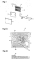
- Once-through forced air-cooled heat sink 10 is comprised of heat sink portion 20 and high static pressure blower 30 that is provided with intake pipe 32 and air supply pipe 31.
- Heat sink portion 20 comprises main body 21, which has fins and flow path 24 of cooling air therein, heat sink cover 22, and heat insulator 42.
- Main body 21 has a back surface that is in contact with a device that is to be cooled, such as a DMD (Digital Micromirror Device) of a projection display apparatus, and allows heat in the device that is to be cooled to be transferred to the fins.
- a device that is to be cooled such as a DMD (Digital Micromirror Device) of a projection display apparatus
- heat sink portion 20 Since the temperature of heat sink portion 20 may rise due to ambient temperature, heat sink portion 20 is covered with heat insulator 42, as illustrated in Fig. 1, in order to prevent external heat from entering heat sink portion 20 through heat sink cover 22 and thereby to limit an increase in the temperature of heat sink portion 20. Since there is a flow of cooling air inside heat sink portion 20, and as a result, the increase in the temperature of the cooling air is limited, the efficiency of cooling a device that is to be cooled can be enhanced. If the influence of ambient temperature on heat sink portion 20 is small, then heat insulator 42 can be omitted. In this case, the function of the heat sink can still be achieved.
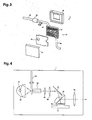
- heat insulator 42 may also be provided on the side of heat sink portion 20 except for the area that is in contact with the device, as illustrated in Fig. 3. This configuration provides a more reliable heat insulating structure which is less affected by the ambient temperature.
- Air supply nozzle 25 is provided at the air inlet of main body 21.
- High static pressure blower 30 is connected to main body 21 via air supply pipe 31 in order to supply cooling air to flow path 24 of main body 21.
- the cross-sectional area of the flow passage is further reduced at air supply nozzle 25 of heat sink portion 20, allowing the cooling air to enter heat sink portion 30 at a higher velocity.
- flow path 24 has a narrow width inside heat sink portion 20. Therefore, cooling air flows through flow path 24 without experiencing a reduction in velocity.
- the amount of heat that is transferred from the fins to the cooling air is correlated to the temperature difference and the velocity of the cooling air on the fins.
- the amount of heat that is transferred per unit time is increased in accordance with the increase in the velocity of the cooling air on the fins. If air supply pipe 31 is not used, the velocity would be reduced because of the increase in the cross-sectional area of the flow passage.
- intake port 33 can also be reduced in size because air supply pipe 31 can achieve cooling with a very low flow rate.
- blower 30 which is small in size and which provides a high static pressure may be used as high static pressure blower 30.
- a pump-type blower which sequentially compresses a plurality of diaphragms by rotation of a motor, can provide a pressure of 50 kPa or more.
- a multistage axial-flow pump may be used as well.
- Bower 30 may have a discharge pressure of any magnitude.
- the discharge pressure of blower 30 may be less than 10kPa, or may be more than 100kPa.
- the cooling air flows around the fins to cool them and flows to exhaust ports 26, as shown in Fig. 2B, along a predetermined once-through path, and is exhausted to the outside.
- a plurality of exhaust ports 26 facilitates exhausting the cooling air which is heated in flow path 24 inside heat sink portion 20. Since the heated cooling air does not remain in flow path 24 for a long time, the efficiency with which a device is cooled can be improved.
- exhaust pipe 41 may be connected to one of the exhaust ports 26, and the remaining exhaust ports 26 may be closed or eliminated.
- the air that is to be exhausted can be transferred through exhaust pipe 41 to a location where the influence of the exhausted air that has been heated is small.
- heat sinks of the present invention may be connected in series.
- the air outlet (exhaust port) of a first heat sink may be connected to the air inlet of a second heat sink by an exhaust pipe.
- a single blower can be used to cool a plurality of heat sinks for a plurality of devices.
- the group of first fins 23a, the group of second fins 23b, and the group of third fins 23c, which are different from other groups in the configuration of the fins, are arranged in flow path 24 inside main body 21.
- An inlet air supply nozzle 25 and a plurality of exhaust ports 26 are provided on opposite side surfaces of main body 21. There are no openings in heat sink portion 20 except for inlet air supply nozzle 25 and exhaust ports 26 when heat sink cover 22 is attached to main body 21.
- the back side of main body 21 is in contact with a device that is to be cooled.
- the group of first fins 23a, the group of second fins 23b, and the group of third fins 23c are configured and arranged such that the cooling air that is supplied by high static pressure blower 30 flows through the entire flow path 24 of main body 21 with which the device that is to be cooled is in contact.
- the fins can prevent reduction in velocity of the cooling air.
- the group of first fins 23a, the group of second fins 23b, and the group of third fins 23c are not limited to the following embodiment, as long as the cooling air introduced via air supply nozzle 25 uniformly cools the fins, and, after cooling, is exhausted from exhaust ports 26 to the outside.
- the fourth embodiment is also an exemplary application of this embodiment.
- the cooling air that is supplied by high static pressure blower 30 is introduced into heat sink portion 20 with a velocity that is increased at air supply nozzle 25.
- the group of first fins 23a which is nearest to air supply nozzle 25, serves to uniformly distribute the cooling air, which is introduced from air supply nozzle 25 with a high velocity, to the entire fins.
- First fin 23a has the shape of an inverted triangle with one apex directed toward air supply nozzle 25.
- First fins 23 are arranged in a staggered pattern in an area near air supply nozzle 25 inside heat sink portion 20.
- the cooling air having a high static pressure flows against the two sides of each first fin 23a that includes the apex, and is distributed through flow path 24, as indicated by the arrows in Fig. 2A.
- first fin 23a is not limited to the inverted triangle.
- first fin 23a may have, for example, an L-shaped configuration with a bend directed toward air supply nozzle 25, as long as it serves to uniformly distribute the cooling air, which is introduced with a high velocity, to the entire fins.
- the group of second fins 23b is arranged adjacent to the group of first fins 23a. As illustrated in Fig. 2A, second fin 23b has a plate-like elongated rectangular configuration.
- the cooling air which is distributed by the group of first fins 23a, flows along the plate-like surfaces and then returns to flow path 24. Since only cooling air with a low static pressure flows in this area because of the configuration of the fins, such a configuration is chosen in order to reduce the resistance.
- the group of third fins 23c is arranged in an upper area relative to the group of first fins 23a, as viewed on the figure, i.e., near exhaust ports 26.
- third fin 23c has a plate-like elongated rectangular configuration.
- the cooling air which is distributed by the group of first fins 23a, flows against the surfaces that are defined by the longer sides of fins 23c in the lowest row, as viewed in the figure, then passes between fins 23c to flow against fins 23c in the next row, then repeats flowing against the next fins and passing between the fins, before it is exhausted from exhaust ports 26.
- the cooling air tends to lose velocity in this area, though it still has a high static pressure. Therefore, third fins 23c form flow passages having small widths in heat sink portion 20 to prevent a reduction in velocity.
- Third fins 23c are arranged in a staggered pattern to facilitate distribution of the cooling air.
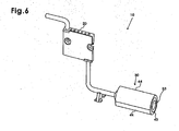
- Once-through forced air-cooled heat sink 11 similar to once-through forced air-cooled heat sink 10 according to the first embodiment, has heat sink portion 20 and high static pressure blower 35.
- High static pressure blower 35 different from the first embodiment in which high static pressure blower 30 is arranged on the side of the air inlet of heat sink portion 20, is arranged on the side of the air outlet of heat sink portion 20.
- intake pipe 37 is connected to the inlet side of high static pressure blower 35 instead of exhaust pipe 41 in the first embodiment, and exhaust pipe 46 is connected to the outlet side of high static pressure blower 35.
- Air supply pipe 36 for receiving cooling air is connected to air supply nozzle 25 of main body 21.
- High static pressure blower 35 is connected to one exhaust port 26 via intake pipe 37 to suck cooling air into heat sink portion 20. Cooling air is introduced into heat sink portion 20 from the outside via air supply pipe 36 and air supply nozzle 25. The cooling air cools fins in heat sink portion 20 in the same manner as in the first embodiment, and is sucked by high static pressure blower 35 to be exhausted to the outside from exhaust ports 26. Similar effects can be obtained in the second embodiment as in the first embodiment. Further, since the cooling air is not heated by the temperature rise in high static pressure blower 30, the fins are less affected by temperature.
- the high static pressure blower can be arranged either on the air inlet side or on the air outlet side, leading to improved flexibility for arranging the once-through forced air-cooled heat sink. If both the intake point of the cooling air and the point at which the cooling air is exhausted are remote from once-through forced air-cooled heat sink 10, high static pressure blower 30 may be provided on the air inlet side, and high static pressure blower 35 may be provided on the air outlet side.
- Heat insulator 47 is provided on the front surface of heat sink portion 20, and heat insulator 48 is provided on the back surface of heat sink portion 20 in Fig. 3.
- the arrangement of the heat insulator is not limited to the embodiment, as described above.
- Projection display apparatus 1 has once-through forced air-cooled heat sink 10 or 11 according to the first or second embodiment.
- the following description will be given regarding an example in which once-through forced air-cooled heat sink 10 or 11 according to the first or second embodiment is used to cool DMD 58 which is an optical modulating device.
- the once-through forced air-cooled heat sink of the present invention may be used, for example, to cool a cold mirror, which is arranged on the emitting side of light source lamp 51 and which removes infrared rays that are included in the illumination system and that are generated by light source lamp 51.
- heat sink portion 20 may be used for other components that generate heat, such as a reflector of light source lamp 51.
- the projection display apparatus is given as an example for the purpose of description, the once-through forced air-cooled heat sink of the present invention is not limited to the projection display apparatus, and can be applied to a variety of components of electronic devices which need cooling.
- light that is emitted from light source lamp 51 is reflected by reflector 52, and is converged on a single point on color wheel 53, which has a combination of color filters to allow red, green, and blue light to selectively pass through.
- the light that is transmitted is uniformized by a light tunnel, not shown, which is disposed in rod integrator box 54, then passes through first condenser lens 55 and second condenser lens 56, and then is reflected in another direction by mirror 57.
- the light that is reflected in another direction is irradiated to DMD 58 via TIR (Total Internal Reflection) prism 58, and the resultant image light, or the light that is reflected by DMD 59, is projected onto a screen, not shown, through projection lens 60.
- TIR Total Internal Reflection
- Once-through forced air-cooled heat sink 10 is in contact with DMD 59 so that the two components are thermally coupled to each other. As illustrated in Figs. 1, 2, cooling air is sucked from intake port 33 of high static pressure blower 30, and fed into flow path 24 in heat sink portion 20 via air supply pipe 31 and air supply nozzle 25, which is arranged at the inlet of heat sink portion 20 of once-through forced air-cooled heat sink 10. After cooling the fins inside heat sink portion 20, the cooling air is exhausted from exhaust ports 26.
- Once-through forced air-cooled heat sink 11 according to the second embodiment may also be provided instead of once-through forced air-cooled heat sink 10.
- the small-size projection display apparatus employs the once-through forced air-cooled heat sink of the present invention, it is possible to reduce the dimensions of the heat sink that is required to cool a DMD, and thereby to reduce the limitation as to where the heat sink can be positioned in an electric apparatus. Further, the use of a high static pressure blower can improve cooling efficiency, while reducing the noise level and limiting the generation of sound having frequencies that are offensive to the ear.
Landscapes
- Physics & Mathematics (AREA)
- Engineering & Computer Science (AREA)
- Thermal Sciences (AREA)
- Mechanical Engineering (AREA)
- General Engineering & Computer Science (AREA)
- General Physics & Mathematics (AREA)
- Optics & Photonics (AREA)
- Projection Apparatus (AREA)
- Cooling Or The Like Of Electrical Apparatus (AREA)
- Cooling Or The Like Of Semiconductors Or Solid State Devices (AREA)
Applications Claiming Priority (1)
| Application Number | Priority Date | Filing Date | Title |
|---|---|---|---|
| JP2005195164A JP4480638B2 (ja) | 2005-07-04 | 2005-07-04 | 貫流型強制空冷ヒートシンクおよび投写型表示装置 |
Publications (2)
| Publication Number | Publication Date |
|---|---|
| EP1742263A2 true EP1742263A2 (fr) | 2007-01-10 |
| EP1742263A3 EP1742263A3 (fr) | 2007-02-21 |
Family
ID=37103258
Family Applications (1)
| Application Number | Title | Priority Date | Filing Date |
|---|---|---|---|
| EP06012678A Withdrawn EP1742263A3 (fr) | 2005-07-04 | 2006-06-20 | Dissipateur thermique refroidi par passage unique d'air forcé pour un dispositif d'affichage par projection |
Country Status (4)
| Country | Link |
|---|---|
| US (1) | US7411789B2 (fr) |
| EP (1) | EP1742263A3 (fr) |
| JP (1) | JP4480638B2 (fr) |
| CN (2) | CN100549810C (fr) |
Cited By (3)
| Publication number | Priority date | Publication date | Assignee | Title |
|---|---|---|---|---|
| AU2013204027A1 (en) * | 2013-03-15 | 2014-10-02 | Regal Beloit Australia Pty Ltd | Air-cooled electric machine and method of assembling the same |
| US9301422B1 (en) | 2015-04-01 | 2016-03-29 | John O. Tate | Heat sink with internal fan |
| US9812920B2 (en) | 2014-09-15 | 2017-11-07 | Regal Beloit America, Inc. | Air-cooled electric machine and method of assembling the same |
Families Citing this family (28)
| Publication number | Priority date | Publication date | Assignee | Title |
|---|---|---|---|---|
| JP2009134201A (ja) * | 2007-12-03 | 2009-06-18 | Funai Electric Co Ltd | プロジェクタ |
| WO2009139065A1 (fr) * | 2008-05-16 | 2009-11-19 | Necディスプレイソリューションズ株式会社 | Unité de pompe de refroidissement et appareil d’affichage par projection présentant ladite pompe |
| US7775062B2 (en) * | 2008-09-15 | 2010-08-17 | Mike Blomquist | Modular cooling system |
| US8490679B2 (en) * | 2009-06-25 | 2013-07-23 | International Business Machines Corporation | Condenser fin structures facilitating vapor condensation cooling of coolant |
| US8344289B2 (en) | 2010-04-21 | 2013-01-01 | Whirlpool Corporation | Terminal block cooling apparatus for an electric cooking range |
| KR20130033736A (ko) * | 2011-09-27 | 2013-04-04 | 삼성전자주식회사 | 프로젝터 및 그를 구비한 디스플레이 장치 |
| JP2013143525A (ja) * | 2012-01-12 | 2013-07-22 | Sumitomo Wiring Syst Ltd | 車両の放熱構造 |
| CN202533862U (zh) * | 2012-02-23 | 2012-11-14 | 周哲明 | 一种低噪音的电脑散热设备 |
| US9217838B2 (en) * | 2012-12-11 | 2015-12-22 | Finisar Corporation | Heat sink retention in an optical component |
| CN104619155A (zh) * | 2015-02-05 | 2015-05-13 | 刘青建 | 一种卧式砂磨机变压电路散热模组 |
| JP6426595B2 (ja) | 2015-12-24 | 2018-11-21 | Necプラットフォームズ株式会社 | 冷却装置 |
| CN106019782B (zh) * | 2016-07-07 | 2018-01-05 | 苏州佳世达电通有限公司 | 投影装置 |
| CN110383470B (zh) * | 2017-03-16 | 2023-05-09 | 三菱电机株式会社 | 冷却系统 |
| JP7139684B2 (ja) | 2018-05-18 | 2022-09-21 | 富士通株式会社 | 冷却装置、及び電子機器 |
| US11856739B2 (en) | 2018-07-23 | 2023-12-26 | Rolls-Royce Deutschland Ltd & Co Kg | Cooling components, converter, and aircraft |
| US10948965B2 (en) | 2018-12-31 | 2021-03-16 | Ecolink Intelligent Technology, Inc. | User-configurable person detection system, method and apparatus |
| US11227476B2 (en) | 2019-03-13 | 2022-01-18 | Ecolink Intelligent Technology, Inc. | Auto-configurable motion/occupancy sensor |
| US11113939B1 (en) | 2020-03-06 | 2021-09-07 | Ecolink Intelligent Technology, Inc. | Person detection apparatus and method |
| US12004322B2 (en) | 2020-12-26 | 2024-06-04 | International Business Machines Corporation | Cold plate with uniform plenum flow |
| US11698233B2 (en) | 2020-12-26 | 2023-07-11 | International Business Machines Corporation | Reduced pressure drop cold plate transition |
| RU2765789C1 (ru) * | 2021-04-26 | 2022-02-03 | Федеральное государственное бюджетное образовательное учреждение высшего образования "Ярославский государственный технический университет" ФГБОУВО "ЯГТУ" | Комбинированная система охлаждения электронных блоков |
| RU2768258C1 (ru) * | 2021-05-04 | 2022-03-23 | Федеральное государственное бюджетное образовательное учреждение высшего образования "Ярославский государственный технический университет" ФГБОУВО "ЯГТУ" | Комбинированная система охлаждения |
| US11650102B2 (en) | 2021-07-22 | 2023-05-16 | Ecolink Intelligent Technology, Inc. | Adjustable dwell time for motion detector based on activity |
| CN113382618A (zh) * | 2021-08-11 | 2021-09-10 | 深圳比特微电子科技有限公司 | 液冷板散热器 |
| DE102021209503A1 (de) * | 2021-08-30 | 2023-03-02 | Robert Bosch Gesellschaft mit beschränkter Haftung | Kühlplatte |
| JP2023096492A (ja) * | 2021-12-27 | 2023-07-07 | キヤノン株式会社 | 冷却装置、投射型表示装置、及び光学装置 |
| JP7574832B2 (ja) * | 2022-08-08 | 2024-10-29 | セイコーエプソン株式会社 | 光透過型光学素子モジュール及び電子機器 |
| EP4700473A1 (fr) * | 2024-08-20 | 2026-02-25 | ASML Netherlands B.V. | Silencieux pour système de conditionnement thermique et son procédé de remplissage, procédé de conditionnement thermique et appareil lithographique |
Family Cites Families (33)
| Publication number | Priority date | Publication date | Assignee | Title |
|---|---|---|---|---|
| US5019880A (en) | 1988-01-07 | 1991-05-28 | Prime Computer, Inc. | Heat sink apparatus |
| US5077601A (en) * | 1988-09-09 | 1991-12-31 | Hitachi, Ltd. | Cooling system for cooling an electronic device and heat radiation fin for use in the cooling system |
| JP3069819B2 (ja) * | 1992-05-28 | 2000-07-24 | 富士通株式会社 | ヒートシンク並びに該ヒートシンクに用いるヒートシンク取付具及びヒートシンクを用いた可搬型電子装置 |
| WO1995025255A1 (fr) * | 1992-09-28 | 1995-09-21 | Aavid Engineering, Inc. | Appareil et procede permettant de refroidir des composants electroniques generant de la chaleur loges dans une armoire |
| US5297005A (en) | 1992-09-28 | 1994-03-22 | Energy Innovations, Inc. | Apparatus and method for cooling heat generating electronic components in a cabinet |
| US5375655A (en) | 1993-03-31 | 1994-12-27 | Lee; Yong N. | Heat sink apparatus |
| JP3236137B2 (ja) * | 1993-07-30 | 2001-12-10 | 富士通株式会社 | 半導体素子冷却装置 |
| JPH07115156A (ja) | 1993-10-19 | 1995-05-02 | Nec Corp | 集積回路の冷却構造 |
| JPH07159070A (ja) | 1993-12-07 | 1995-06-20 | Matsushita Seiko Co Ltd | ヒートシンクの冷却装置 |
| US5582240A (en) * | 1994-09-19 | 1996-12-10 | Motorola, Inc. | Pneumatically coupled heat sink assembly |
| JP2894243B2 (ja) | 1995-05-24 | 1999-05-24 | 住友金属工業株式会社 | 熱放散特性に優れたヒートシンク |
| US5957194A (en) * | 1996-06-27 | 1999-09-28 | Advanced Thermal Solutions, Inc. | Plate fin heat exchanger having fluid control means |
| DE19643717A1 (de) * | 1996-10-23 | 1998-04-30 | Asea Brown Boveri | Flüssigkeits-Kühlvorrichtung für ein Hochleistungshalbleitermodul |
| US6714278B2 (en) * | 1996-11-25 | 2004-03-30 | Nikon Corporation | Exposure apparatus |
| JP2860293B2 (ja) | 1997-07-09 | 1999-02-24 | 三菱電機株式会社 | 発熱体の水蒸発式冷却装置 |
| US6113485A (en) * | 1997-11-26 | 2000-09-05 | Advanced Micro Devices, Inc. | Duct processor cooling for personal computer |
| US5917697A (en) * | 1998-01-27 | 1999-06-29 | Wang; Daniel | CPU cooling arrangement |
| US5946188A (en) * | 1998-07-29 | 1999-08-31 | Epsilon Electronics, Inc. | Car amplifier incorporating a peltier device for cooling |
| JP3120802B2 (ja) | 1999-03-15 | 2000-12-25 | 富士通株式会社 | ヒートシンク |
| TW505254U (en) * | 1999-09-23 | 2002-10-01 | Foxconn Prec Components Co Ltd | Heat sink module having air guiding device |
| US6729383B1 (en) | 1999-12-16 | 2004-05-04 | The United States Of America As Represented By The Secretary Of The Navy | Fluid-cooled heat sink with turbulence-enhancing support pins |
| US6940716B1 (en) * | 2000-07-13 | 2005-09-06 | Intel Corporation | Method and apparatus for dissipating heat from an electronic device |
| TW588932U (en) * | 2000-12-20 | 2004-05-21 | Foxconn Prec Components Co Ltd | Heat sink module |
| US6567267B1 (en) * | 2002-02-14 | 2003-05-20 | Terry Wang | Apparatus capable of air-filtering and heat-dissipating and adapted for use in a computer |
| US6935419B2 (en) | 2002-02-20 | 2005-08-30 | Hewlett-Packard Development Company, L.P. | Heat sink apparatus with air duct |
| JP2003259600A (ja) | 2002-03-06 | 2003-09-12 | Toyota Motor Corp | 車載用電気装置の冷却構造 |
| US6888720B2 (en) * | 2002-06-18 | 2005-05-03 | Sun Microsystems, Inc. | Distributed graphitic foam heat exchanger system |
| US6690577B2 (en) * | 2002-07-02 | 2004-02-10 | Hewlett-Packard Development Company, L.P. | Air guide |
| US6655449B1 (en) * | 2002-11-08 | 2003-12-02 | Cho-Chang Hsien | Heat dissipation device by liquid cooling |
| JP4228680B2 (ja) | 2002-12-12 | 2009-02-25 | 三菱電機株式会社 | 冷却部材 |
| US6971243B2 (en) | 2003-08-12 | 2005-12-06 | Coolit Systems Inc. | Heat sink |
| US20050047086A1 (en) | 2003-08-27 | 2005-03-03 | Elias Gedamu | Heat dissipation apparatus and method |
| JP4257311B2 (ja) * | 2005-04-06 | 2009-04-22 | Necディスプレイソリューションズ株式会社 | 投写型表示装置 |
-
2005
- 2005-07-04 JP JP2005195164A patent/JP4480638B2/ja not_active Expired - Fee Related
-
2006
- 2006-06-14 US US11/452,253 patent/US7411789B2/en not_active Expired - Fee Related
- 2006-06-20 EP EP06012678A patent/EP1742263A3/fr not_active Withdrawn
- 2006-06-28 CN CN200610095728.2A patent/CN100549810C/zh not_active Expired - Fee Related
- 2006-06-29 CN CN200620119572.2U patent/CN200983066Y/zh not_active Expired - Lifetime
Non-Patent Citations (1)
| Title |
|---|
| None * |
Cited By (5)
| Publication number | Priority date | Publication date | Assignee | Title |
|---|---|---|---|---|
| AU2013204027A1 (en) * | 2013-03-15 | 2014-10-02 | Regal Beloit Australia Pty Ltd | Air-cooled electric machine and method of assembling the same |
| AU2013204027B2 (en) * | 2013-03-15 | 2016-04-14 | Regal Beloit Australia Pty Ltd | Air-cooled electric machine and method of assembling the same |
| US9467030B2 (en) | 2013-03-15 | 2016-10-11 | Regal Beloit Australia Pty Ltd | Air-cooled electric machine and method of assembling the same |
| US9812920B2 (en) | 2014-09-15 | 2017-11-07 | Regal Beloit America, Inc. | Air-cooled electric machine and method of assembling the same |
| US9301422B1 (en) | 2015-04-01 | 2016-03-29 | John O. Tate | Heat sink with internal fan |
Also Published As
| Publication number | Publication date |
|---|---|
| EP1742263A3 (fr) | 2007-02-21 |
| CN200983066Y (zh) | 2007-11-28 |
| JP2007013052A (ja) | 2007-01-18 |
| JP4480638B2 (ja) | 2010-06-16 |
| US7411789B2 (en) | 2008-08-12 |
| CN1892414A (zh) | 2007-01-10 |
| CN100549810C (zh) | 2009-10-14 |
| US20070000650A1 (en) | 2007-01-04 |
Similar Documents
| Publication | Publication Date | Title |
|---|---|---|
| US7411789B2 (en) | Once-through forced air-cooled heat sink for a projection display apparatus | |
| US7248472B2 (en) | Air distribution system | |
| TWI417635B (zh) | 電子裝置及投影機 | |
| US8087788B2 (en) | Projector with cooling configuration | |
| US8770765B2 (en) | Thermal management of very small form factor projectors with synthetic jets | |
| US20060185830A1 (en) | Cooling plate module | |
| KR100688978B1 (ko) | 영상투사장치 | |
| JP2004116864A5 (fr) | ||
| CN205982964U (zh) | 投影装置及其散热系统 | |
| CN101063798B (zh) | 投射型视频显示装置 | |
| CN100498512C (zh) | 投射型视频显示装置 | |
| US8226243B2 (en) | Light source module and projector having same | |
| US20100181886A1 (en) | Heat dissipating module | |
| JP2007103748A (ja) | 熱交換器、液冷システム、光源装置、プロジェクタ、電子デバイスユニット、電子機器 | |
| JP2009295869A (ja) | 電子機器の冷却装置 | |
| JP5289352B2 (ja) | 冷却構造 | |
| WO2020075266A1 (fr) | Unité extérieure | |
| JP2003023283A (ja) | 電子部品の冷却装置 | |
| CN205787552U (zh) | 投影装置及其散热模组 | |
| JP2009282313A (ja) | 冷却装置および投写型映像表示装置 | |
| CN113325658B (zh) | 散热箱及包含它的多媒体投影仪 | |
| US20050092468A1 (en) | Water tray of liquid based cooling device | |
| CN106896629A (zh) | 投影仪 | |
| CN221686804U (zh) | 投影仪 | |
| JP7591733B2 (ja) | 冷却装置およびそれを備えるプロジェクタ |
Legal Events
| Date | Code | Title | Description |
|---|---|---|---|
| PUAI | Public reference made under article 153(3) epc to a published international application that has entered the european phase |
Free format text: ORIGINAL CODE: 0009012 |
|
| AK | Designated contracting states |
Kind code of ref document: A2 Designated state(s): AT BE BG CH CY CZ DE DK EE ES FI FR GB GR HU IE IS IT LI LT LU LV MC NL PL PT RO SE SI SK TR |
|
| AX | Request for extension of the european patent |
Extension state: AL BA HR MK YU |
|
| PUAL | Search report despatched |
Free format text: ORIGINAL CODE: 0009013 |
|
| AK | Designated contracting states |
Kind code of ref document: A3 Designated state(s): AT BE BG CH CY CZ DE DK EE ES FI FR GB GR HU IE IS IT LI LT LU LV MC NL PL PT RO SE SI SK TR |
|
| AX | Request for extension of the european patent |
Extension state: AL BA HR MK YU |
|
| 17P | Request for examination filed |
Effective date: 20070308 |
|
| RAP1 | Party data changed (applicant data changed or rights of an application transferred) |
Owner name: NEC DISPLAY SOLUTIONS, LTD. |
|
| AKX | Designation fees paid |
Designated state(s): DE FR GB |
|
| 17Q | First examination report despatched |
Effective date: 20140807 |
|
| STAA | Information on the status of an ep patent application or granted ep patent |
Free format text: STATUS: THE APPLICATION IS DEEMED TO BE WITHDRAWN |
|
| 18D | Application deemed to be withdrawn |
Effective date: 20181128 |