EP1742337A2 - Procédé et appareil pour une réponse conditionnée dans le conditions de défauts dans une alimentation de puissance de commutation - Google Patents
Procédé et appareil pour une réponse conditionnée dans le conditions de défauts dans une alimentation de puissance de commutation Download PDFInfo
- Publication number
- EP1742337A2 EP1742337A2 EP06253512A EP06253512A EP1742337A2 EP 1742337 A2 EP1742337 A2 EP 1742337A2 EP 06253512 A EP06253512 A EP 06253512A EP 06253512 A EP06253512 A EP 06253512A EP 1742337 A2 EP1742337 A2 EP 1742337A2
- Authority
- EP
- European Patent Office
- Prior art keywords
- power converter
- output
- voltage
- coupled
- input
- Prior art date
- Legal status (The legal status is an assumption and is not a legal conclusion. Google has not performed a legal analysis and makes no representation as to the accuracy of the status listed.)
- Withdrawn
Links
- 238000000034 method Methods 0.000 title abstract description 5
- 230000035045 associative learning Effects 0.000 title description 10
- 238000012546 transfer Methods 0.000 claims abstract description 19
- 230000001105 regulatory effect Effects 0.000 claims abstract description 16
- 230000004044 response Effects 0.000 claims abstract description 11
- 238000001514 detection method Methods 0.000 claims abstract description 7
- 238000004804 winding Methods 0.000 claims description 24
- 239000003990 capacitor Substances 0.000 description 24
- 230000008901 benefit Effects 0.000 description 3
- 230000003287 optical effect Effects 0.000 description 3
- 230000009471 action Effects 0.000 description 2
- 230000004888 barrier function Effects 0.000 description 2
- 238000010586 diagram Methods 0.000 description 2
- 230000006870 function Effects 0.000 description 2
- 238000002955 isolation Methods 0.000 description 2
- 230000011664 signaling Effects 0.000 description 2
- 230000000903 blocking effect Effects 0.000 description 1
- 230000008878 coupling Effects 0.000 description 1
- 238000010168 coupling process Methods 0.000 description 1
- 238000005859 coupling reaction Methods 0.000 description 1
- 230000003247 decreasing effect Effects 0.000 description 1
- 230000007547 defect Effects 0.000 description 1
- 230000001419 dependent effect Effects 0.000 description 1
- 238000013461 design Methods 0.000 description 1
- 238000012986 modification Methods 0.000 description 1
- 230000004048 modification Effects 0.000 description 1
- 238000012544 monitoring process Methods 0.000 description 1
- 230000010355 oscillation Effects 0.000 description 1
- 238000012545 processing Methods 0.000 description 1
- 230000002035 prolonged effect Effects 0.000 description 1
- 230000000630 rising effect Effects 0.000 description 1
- 230000008646 thermal stress Effects 0.000 description 1
- 230000001052 transient effect Effects 0.000 description 1
Images

Classifications
-
- H—ELECTRICITY
- H02—GENERATION; CONVERSION OR DISTRIBUTION OF ELECTRIC POWER
- H02M—APPARATUS FOR CONVERSION BETWEEN AC AND AC, BETWEEN AC AND DC, OR BETWEEN DC AND DC, AND FOR USE WITH MAINS OR SIMILAR POWER SUPPLY SYSTEMS; CONVERSION OF DC OR AC INPUT POWER INTO SURGE OUTPUT POWER; CONTROL OR REGULATION THEREOF
- H02M1/00—Details of apparatus for conversion
- H02M1/32—Means for protecting converters other than automatic disconnection
-
- H—ELECTRICITY
- H02—GENERATION; CONVERSION OR DISTRIBUTION OF ELECTRIC POWER
- H02M—APPARATUS FOR CONVERSION BETWEEN AC AND AC, BETWEEN AC AND DC, OR BETWEEN DC AND DC, AND FOR USE WITH MAINS OR SIMILAR POWER SUPPLY SYSTEMS; CONVERSION OF DC OR AC INPUT POWER INTO SURGE OUTPUT POWER; CONTROL OR REGULATION THEREOF
- H02M3/00—Conversion of DC power input into DC power output
- H02M3/22—Conversion of DC power input into DC power output with intermediate conversion into AC
- H02M3/24—Conversion of DC power input into DC power output with intermediate conversion into AC by static converters
- H02M3/28—Conversion of DC power input into DC power output with intermediate conversion into AC by static converters using discharge tubes with control electrode or semiconductor devices with control electrode to produce the intermediate AC
- H02M3/325—Conversion of DC power input into DC power output with intermediate conversion into AC by static converters using discharge tubes with control electrode or semiconductor devices with control electrode to produce the intermediate AC using devices of a triode or a transistor type requiring continuous application of a control signal
- H02M3/335—Conversion of DC power input into DC power output with intermediate conversion into AC by static converters using discharge tubes with control electrode or semiconductor devices with control electrode to produce the intermediate AC using devices of a triode or a transistor type requiring continuous application of a control signal using semiconductor devices only
- H02M3/33507—Conversion of DC power input into DC power output with intermediate conversion into AC by static converters using discharge tubes with control electrode or semiconductor devices with control electrode to produce the intermediate AC using devices of a triode or a transistor type requiring continuous application of a control signal using semiconductor devices only with automatic control of the output voltage or current, e.g. flyback converters
Definitions
- the present invention relates generally to electronic circuits, and more specifically, the invention relates to circuits that respond to fault conditions.
- Off-line switching power supplies generally use a control loop for regulating an output parameter such as the output voltage(s) and or current(s). For safety reasons it is often necessary that these power supplies have a way to help protect the entire system in case of a fault condition where for example the regulation is lost or the power converter exceeds a temperature threshold. Otherwise, the output circuitry or the attached load or in worst case a person touching the output or power converter enclosure may be harmed under such a condition.
- a loss of regulation or exceeding a temperature threshold can have various causes in a power supply.
- a loss of regulation may be caused by a defect component in the control loop.
- An example would be a faulty optical coupler typically used for coupling a feedback signal across the isolation barrier from the output or secondary back to the input or primary side of the power supply.
- a loss of regulation may be caused by an output overload condition or an output short circuit condition.
- an output overload condition the output voltage drops below its regulation value once the power supply cannot deliver the requested power anymore.
- an output short circuit condition the output voltage drops close to zero. In both cases the power demanded exceeds the capability of the power supply. The regulation is lost.
- a loss of regulation can also occur during a normal power down, such as for example when the power supply is unplugged from the line, because once the alternating current (AC) input voltage is removed the input voltage to the power supply will eventually fall so low that the converter is unable to deliver the output power and the regulation will be lost.
- Another example for this last cause of lost regulation is a temporary sag in the AC or line input voltage.
- the temperature of various components in the power converter typically come under additional thermal stress, which in turn can lead to individual components or the complete converter exceeding a safe temperature threshold value.
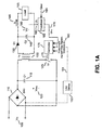
- Figure 1A is an example schematic for an embodiment of a power converter in which there are conditional responses to fault conditions in accordance with the teaching of the present invention.
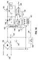
- Figure 1B is another example schematic for an embodiment of a power converter in which there are conditional responses to fault conditions in accordance with the teaching of the present invention.
- Figure 2 is an example flow diagram for an embodiment in which there are conditional responses to fault conditions in a power converter in accordance with the teaching of the present invention in accordance with the teaching of the present invention.
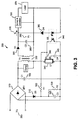
- Figure 3 is another example schematic for an embodiment of a power converter in which there are conditional responses to fault conditions in accordance with the teaching of the present invention.
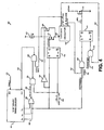
- Figure 4 is an example schematic for an embodiment of an integrated circuit included in a power converter in which there are conditional responses to fault conditions in accordance with the teaching of the present invention.
- a conditional response to a fault condition in a power supply is provided in accordance with the teachings of the present invention.
- An example application would be a power supply for a printer.
- the power supply should latch off if for example a loss of regulation is detected or if for example a temperature threshold is exceeded.
- Those circumstances include output short circuit or output overload or a broken control loop due to a faulty component while the power supply input voltage is within the normal operating range or in other words above a threshold value that is set in the design of the power supply to meet the normal operating specifications of that supply.
- No automatic restart attempt should be undertaken. Otherwise, the motor transporting the paper in an inkjet printer may be damaged for instance in case the paper is jammed.
- a latching shutdown in response to a fault condition should be avoided. Under this condition an automatic restart is desirable when the input voltage again returns to within the normal operating range of the power supply.
- Methods and apparatuses are disclosed herein that address the problem of control systems that are not able to detect the nature of the cause for the fault condition.
- the designer can choose between a latching shutdown when the input voltage is above a threshold level, or a hysteretic or automatic restart shutdown if the fault condition is due to the input voltage being below a threshold level.
- the power supply initiates a restart attempt when the input voltage again rises above a threshold level.
- a power supply controller can differentiate the nature of the fault condition and decide different actions depending on the additional information received after the fault condition has been detected provided in accordance with the teachings of the present invention.
- this has the benefit of allowing both fault condition detection and input voltage sensing to be performed on a single pin of an integrated circuit controller circuit with the integrated circuit being latched into an off condition if the input voltage is above a threshold value following detection of a fault condition.
- Figure 1A shows an example a power converter where one or more of a plurality of inputs 180 are coupled to a controller circuit of the power converter to detect a fault condition in accordance with the teachings of the present invention.
- Those signals included in the plurality of inputs 180 can indicate that a fault is present in the power converter and can include, but are not limited to, one or more of a signal representative of the line input voltage, a regulated output parameter of the power supply and/or a thermal signal.
- the signal representative of the regulated output parameter of the power supply may be employed to indicate a fault condition in the power converter of a loss of regulation of the output parameter of the power converter.
- the thermal signal may be representative of a temperature of a component within the power converter and may therefore be employed to indicate that there is a thermal fault condition in the power converter.
- the plurality of inputs 180 may therefore be used to first detect a fault condition and then determine the reason for the fault condition including for example signals representative of an AC input voltage or DC bus (bulk) voltage in accordance with the teachings of the present invention.
- signals representative of an AC input voltage or DC bus (bulk) voltage in accordance with the teachings of the present invention.
- various examples of the power converter for an embodiment are coupled to have conditional responses to the detected fault conditions in accordance with the teachings of the present invention.
- the AC line voltage V IN 105 is rectified by the bridge rectifier BR1 110 and smoothed with the bulk capacitor C1 115.
- the power is delivered to the load 155 via an energy transfer element T1 130 in response to the switching of a power switch S 1 125, which is coupled to the input of the energy transfer element T1 130.
- the energy transfer element T1 130 is illustrated as a transformer.
- the transformer output voltage is rectified and smoothed by the rectifier D1 135 and the capacitor C2 140.
- the output parameter such as output voltage Vo 150, output current I o 145, or a combination of Vo 150 and I o 145, is regulated via the feedback circuit 165 and the controller 175.
- the feedback circuit 165 is directly coupled to the output of the power supply to sense the output of the power supply.
- feedback circuit 165 compares a representation of the output voltage U o 160 with a reference voltage U REF 185 for generating the feedback signal U FB 170.
- This feedback signal U FB 170 is processed by the controller 175 for regulating the output parameter such as voltage V o 150 or output current I o 145.
- feedback signal U FB can be one of the plurality of inputs 170 providing a means of detecting a loss of regulation of an output parameter such as voltage V o 150 or output current I o 145.
- controller 175 generates a drive signal 176 which is coupled to control the switching of power switch S 1 125 to regulate an output parameter of the power converter.
- the output 151 of an input line sense circuit 152 is one of a plurality of inputs 180 to controller 175.
- the function of line sense circuit 152 is to monitor the magnitude of the AC input voltage V IN 105.
- FIG. 1B shows an example a power converter sharing many similarities with the power converter of Figure 1A but with the addition of a bias winding 188 forming part of the energy transfer element 197.
- the AC line voltage V IN 190 is rectified by the bridge rectifier BR1 192 and smoothed with the bulk capacitor C1 193.
- the power is delivered to the load 164 via an energy transfer element T1 197 in response to the switching of a power switch S 1 196, which is coupled to the input of the energy transfer element T1 197.
- power switch S 1 196 is switched in response to a drive signal 173 received from controller 187.
- controller 197 is coupled to receive a plurality of inputs 181, which includes a feedback signal U FB 182 from feedback circuit 183.
- feedback circuit 183 is coupled to receive a reference voltage U REF 186.
- the energy transfer element T1 197 is illustrated as a transformer. The transformer output voltage is rectified and smoothed by the rectifier D1 198 and the capacitor C2 199. The output parameter, such as output voltage Vo 162 or output current I o 163, is regulated via the feedback circuit 183 and the controller 187.
- the circuit of Figure 1 B has a bias winding 188 which can be used to provide a low voltage power source to supply controller 187 and/or generate an output signal representative of the output voltage 162 to the feedback circuit 183.
- the bias winding signal 189 is coupled to the feedback circuit 183, signal 184 is no longer required and instead the controller 187 will adapt to switch switch 196 to regulate the bias winding signal 189.
- the bias winding signal being regulated can be a voltage across the bias winding 188 or a current derived from the voltage across bias winding 188.
- the loss of regulation of the power converter output parameter, Vo 162 is detected by sensing the bias winding output signal 189 generated by the bias winding.
- FIG. 2 shows a flowchart of the operation under various fault conditions.
- the AC input voltage is above a startup threshold level at block 210.
- This block confirms that the input voltage to the power supply is high enough to maintain regulation of the required output parameter.
- switching refers to the operation of the power switch, such as for example switch S 1 125 in Figure 1A, and is used to describe the action of delivering energy to the power converter output load.
- block 230 constantly monitors the control loop to check if the output parameter being regulated is still in regulation. It is appreciated that in an alternative embodiment, block 230 could instead be monitoring the temperature of one or more of the power converter power switch, such as for example switch S 1 125 in Figure 1A, or the energy transfer element or any other components within the power converter in accordance with the teachings of the present invention. The decision made at block 230 would then be whether the component or components, whose temperature is being monitored, are below a temperature threshold value.
- Switching can be terminated immediately regulation is lost or after a time period from the point where regulation is lost, in order to allow for conditions during the normal operation of the power converter where regulation could be lost for short periods such as very high transient load conditions.
- block 250 After the regulation has been lost, block 250 then detects whether the regulation loss could be due to the AC line voltage being below a threshold, here called the restart threshold level. If the AC line voltage is above this restart threshold level, the cause of the lost regulation is assumed to be either a broken control loop or an output overload or short circuit. In all these cases the power supply is latched off.
- the restart threshold level a threshold
- the cause of the lost regulation is assumed to be either a broken control loop or an output overload or short circuit. In all these cases the power supply is latched off.
- the latch is reset, as shown at block 260.
- a normal power down or AC line sag may be the cause for the regulation loss and restart attempts are permitted.
- block 270 establishes an off time period after which the power converter attempts to restart when the AC input voltage again rises above the startup threshold, as determined at block 280.
- the off time period could be zero and the power supply operation would then immediately restart if the input voltage level is above the startup threshold, as shown in block 280.
- the presence of block 250 ensures the AC line is continuously monitored after the switching is stopped.
- the input voltage startup and restart threshold levels are substantially equal.
- the circuitry to employ blocks 210 and 280 are identical, in which case processing after block 270 would continue with block 210 instead of block 280, in accordance with the teachings of the present invention.
- FIG. 3 is an illustration of a converter 300 for an embodiment in accordance with the teachings of the present invention.
- the feedback signal and the AC line voltage sense signal are combined on one feedback terminal EN 390 of controller 340 to reduce the number inputs to controller U 340 and therefore reduce system cost.
- the feedback and the AC line voltage sense could be applied to separate terminals of controller U1 340.
- the controller U1 340 includes the switch coupled between the D and S terminals. By including the switch in the controller U 340, system cost may be reduced. In another embodiment, the switch could also be external to controller U1 340 in accordance with the teachings of the present invention.
- the AC line voltage V IN 305 is rectified and smoothed by the bridge rectifier BR1 310 and the DC bulk capacitor C1 335.
- the energy transfer element T1 350 together with the switch integrated in controller U1 340 are coupled to regulate the delivery of energy to the load 375.
- the transformer T1 350 output voltage is rectified and smoothed by the rectifier D1 355 and the capacitor C2 360.
- the regulated output parameter is the output voltage V o 365.
- An output voltage regulation threshold is set by Zener diode D4 380 and the forward voltage drop of optical coupler U2 385 LED.
- Optical coupler U2 385 couples a feedback signal across the isolation barrier to the feedback terminal EN 390 of integrated circuit U1 340.
- a loss of regulation of the output parameter is indicated by the loss of the feedback signal to the feedback terminal EN 390.
- this loss of regulation could be due to an output short circuit or overload condition at the output of the power converter for example.
- Figure 3 shows a circuit 395 which can create a loss of regulation.
- sense and crowbar circuit 395 comprises current sensing circuitry which senses the magnitude of output current I o 370 and triggers a crowbar circuit which applies a substantially short circuit across the output of the power converter if I o 370 exceeds a threshold value or exceeds a threshold value for a period of time. Circuit 395 therefore creates a loss of regulation based on an output load condition.
- This type of circuit can be used in for example a power converter for a printer to detect a load condition which would not in itself generate a loss of regulation but which nevertheless is undesirable since it exceeds a maximum power delivery specification set by the manufacturer of the printer.
- Sense and crowbar circuit 395 provides this function and allows the power converter designer to set the threshold at which this fault condition is generated.
- Capacitor C4 345 acts as bypass for the internal supply of controller U1 340.
- controller U1 340 is adapted to be responsive to a feedback current signal flowing out of feedback terminal EN 390.
- controller 340 could be adapted to be responsive to a feedback voltage at terminal EN 390 in accordance with the teachings of the present invention.
- controller 340 could be adapted to be responsive to a feedback current signal flowing into feedback terminal EN 390.
- Controller 340 detects when this feedback current signal exceeds a threshold value determined by circuitry internal to controller 340.
- Controller 340 is adapted to control energy transfer through energy transfer element 350 in order to regulate the feedback current signal at feedback terminal EN 390.
- controller 340 uses an ON/OFF control scheme to achieve this regulation.
- controller 340 could use pulse width modulator (PWM) voltage mode or PWM current mode or resonant mode or quasi-resonant mode control to achieve this regulation in accordance with the teachings of the present invention.
- PWM pulse width modulator
- components 315, 320, 330 and 325 make up a line sense circuit, such as the example illustrated in Figure 1A of the line sense block 152 shown in Figure 1A.
- the AC input voltage V IN 305 is rectified and smoothed by the rectifier D3 315 and the capacitor C3 325.
- Capacitor 325 charges to the peak value of the AC input and is discharged by resistors 330 and 320 over time.
- the relative values of capacitor 325, resistor 330 and resistor 320 determine the value of the voltage across capacitor 325 over time when diode 315 is not conducting.
- capacitor 325 has a value of 33nF
- resistor 330 has a value of 6.8 Megaohms
- resistor 320 has a value of 10 Megaohms.
- the time constant of this combination of values would then be approximately 132 milliseconds. This time constant is chosen such that it is much longer than the cycle of an AC voltage waveform which is typically approximately 16.6 milliseconds when the AC line voltage frequency is 60 Hertz. The choice of a 132 millisecond time constant therefore ensures that the voltage across 325 is held up between AC line cycles but is discharged relatively quickly if the AC input voltage is disconnected or sags.
- the values of capacitor 325, resistor 330 and resistor 320 could all be increased or decreased to increase or decrease the time taken to discharge capacitor 325, whilst still benefiting from the teachings of the present invention.
- the resistor 330 is not required since the current flowing in resistor 320 is adequate to provide the desired value of the voltage across 325 over time when diode 315 is not conducting.
- Applications which benefit from the teachings of the present invention normally require that the user of the power supply is able to reset the power supply by removing the AC input voltage and that this reset takes place in a short period of time typically between 1 and 10 seconds.
- capacitor 325 when AC input voltage is removed is therefore the reason that line voltage sensing is not achieved by detecting the voltage across capacitor 335, which is normally very large in value and therefore can take a very long period to discharge.
- input voltage information may be derived from the voltage across capacitor C1 335 if a longer period to reset the power supply was acceptable.
- diode D3 315 and capacitor C3 325 would be eliminated and resistor 320 would be coupled between the feedback terminal EN 390 and the input DC rail at the positive terminal of capacitor C 1 335.
- a resistor such as R2 330 could in that case be coupled across capacitor C1 335 to influence the time constant of the voltage across capacitor C1 335 and therefore the time taken to reset the power supply when the input voltage is removed.
- An example of a case where this type of embodiment might be used is when the power supply is fed with a DC rather than AC supply.
- controller U1 340 is adapted to sense a magnitude of current flowing through resistor 320 after regulation of the output parameter is lost. Circuitry internal to controller 340 sets a threshold value of this current referred to here as the line sense threshold current. For one embodiment, a current flowing in resistor 320 of less than this threshold value is interpreted as indicating that the AC input voltage is not high enough to allow the power converter to deliver the required energy to the power converter output load and bring the output parameter into regulation in accordance with the teachings of the present invention.
- controller U1 340 In case of a loss of regulation due to an output overload or a short circuit, controller U1 340 detects the loss of feedback signal coupled to the feedback terminal EN 390 by opto-coupler 385 and stops switching as described in Figure 2. However, with the benefit of the teachings of the present invention, the controller 340 is able to determine the reason for this loss of regulation.
- the controller 340 initiates a latch off condition.
- This latch off condition is reset by removing or reducing the AC input voltage until the current flowing through resistor 320 is below the line sense threshold current of controller 340.
- the line sense threshold current of controller 340 is typically set at a level corresponding to an AC voltage having for example 50 to 100 Volts peak voltage.
- a degree of hysteresis may be applied to the line sense threshold current level.
- the controller 340 sets an off period after which the controller attempts to restart the power converter if at the end of the off time period, the current flowing through resistor 320 is above the sense threshold current level.
- the line sense threshold could be a voltage threshold rather than a current threshold while still benefiting from the teachings of the present invention.
- the circuit example of Figure 3 employs a controller 340, which provides supply current to the internal circuitry using charge stored on bypass capacitor 345, which is derived from an internal regulator circuit of controller U1 340 coupled between the D terminal and the BP terminal of controller U1 340.
- the supply current for controller U1 340 to operate could be derived from a low voltage bias winding forming part of energy transfer element 350.
- the bias winding would output a signal that could be coupled to be received by controller U1 340 that is representative of the output of the power supply.
- the signal output by the bias winding representative of the output of the power supply and received by the controller U1 340 could be a voltage of the bias winding or a current derived from the bias winding in accordance with the teachings of the present invention.
- the bias winding could therefore also be used to detect the loss of regulation at the output of converter 300.
- the voltage appearing across a bias winding is substantially proportional to the output voltage of the converter.
- an output overload or short circuit fault on the output of the power converter can be sensed by the bias winding voltage dropping below a threshold value. This operation is consistent with the description of Figure 1B.
- an open control loop condition for example if opto-coupler 385 fails as an open circuit, the consequent output over-voltage condition could again be sensed by the bias winding voltage rising above a threshold value.
- a power converter output over-voltage condition could be sensed directly at the output of the power converter and a signal provided to the power supply controller to indicate this fault condition through a second optocoupler used specifically for the purpose in accordance with the teachings of the present invention.
- Figure 4 shows a block diagram 400 of one example of a circuit providing conditional response to a fault condition in accordance with the teachings of the present invention.
- the example circuit shown in Figure 4 would for example form part of the internal control circuitry of controller U1 340 in Figure 3, or controller 175 and switch S 1 125 of Figure 1 A, and/or form some of the operations shown in the flowchart of Figure 2 in accordance with the teachings of the present invention.
- AND gate 415 has three input signals. During normal operation, at the beginning of each switch cycle of power switch 418, oscillator 419 generates a clock pulse 421. As illustrated in the depicted example, input 422 of oscillator 419 is coupled to receive current from current source 412 through MOSFET 411 and/or MOSFET 425. When oscillator 419 is supplied with current from current source 412, oscillation of oscillator 419 is enabled. Assuming there is no fault condition and the feedback signal represented internally as ENABLE signal 413 is high, the output of AND gate 415 goes high for the duration of the CLOCK signal 421, which sets latch or flip flop 417 turning on power switch 418.
- flip flop 417 generates drive signal 476, which is coupled to be received by switch 418 to control the switching of power switch 418.
- the time for which power switch 418 remains on is determined by the CURRENT LIMIT bar signal 414 and DC MAX signal 420. Either of these signals going low will reset flip flop 417 and terminate the on time of the power switch 418.
- counter 401 During normal operation, each time the ENABLE signal 413 goes low, counter 401 is set. However, under a fault condition where the ENABLE signal 413 is lost, which indicates a loss of regulation of the output in the circuit of Figure 3 for example, and which in Figure 2 corresponds to the YES output of block 230, counter 401 continues to count without being set by the ENABLE signal 413. Counter 401 is clocked at the oscillator frequency with signal 407 from oscillator 419.
- counter 401 is a down counter and therefore counts down from a condition where signals Q 12 , Q 13 and Q 14 start high to one where they are low.
- counter bits Q 1 to Q 11 are also included, but not shown in Figure 4.
- Q 14 output of counter 401 is high, the output of inverter gate 409 is low, maintaining p channel MOSFET 425 in the on state, which allows the oscillator to be supplied by current source 412 and operate normally.
- S input to latch 410 and therefore Q output of latch 410 are therefore high, which ensures p channel MOSFET 411 is held off and plays no part in the operation of the oscillator regardless of the polarity of LINE UV signal 408.
- the controller operation while regulating power is unresponsive to the condition of the signal representative of the power converter input voltage in accordance with the teachings of the present invention.
- inverter 409 output goes high turning off p channel MOSFET 425.
- the response of latch 410 to Q 14 going low is dependent on the condition of the LINE UV signal 408.
- LINE UV signal 408 is high, signaling for example that the power supply input voltage 305 in Figure 3 is below a threshold value, then Q output of latch 410 goes low and p channel MOSFET 411 turns on allowing the oscillator to continue operating or oscillating.
- CLOCK INPUT 407 therefore continues to provide clock input signal 423 to the counter 401 and the counter continues to down count until Q 13 and Q 12 go low in common with Q 14 (which is already low from above).
- END OF COUNT signal 405 goes high. Since in this first case, LINE UV signal is also high, output of NAIVD gate 404 goes low and CLOCK INPUT 407 to NAND gate 406 is blocked from influencing the input CLK signal 423 to counter 401.
- the counter 401 is therefore held in this condition until the LINE UV signal 408 goes low, which indicates for example the power supply input voltage 308 in Figure 3 has risen above a threshold value. Under this condition, output of NAND gate 404 goes high and CLOCK INPUT 407 to NAND gate 406 is again able to clock the input CLK signal 423 to counter 401 at the frequency of the oscillator 419. The counter 401 then counts to the next state where Q 1 to Q 14 again go high, and the count starts again. Since Q 14 is now high, power MOSFET 418 is again allowed to switch depending on the states of the ENABLE 413 and CLOCK 421 inputs to AND gate 415. This series of events is corresponds to the YES output of block 280 and block 220 in Figure 2.
- LINE UV signal 408 is low, signaling for example that the power supply input voltage 305 in Figure 3 is above a threshold value, then Q output of latch 410 remains high and p channel MOSFET 411 is off, blocking current source 412 from supplying the oscillator 419.
- the oscillator 419 therefore ceases oscillating and CLOCK INPUT 407 therefore generates no clock input signal 423 to the counter 401.
- the counter 401 is then held in the current state, effectively latching this condition. Therefore, under this fault condition, the power converter is latched in the off state. In Figure 2, this corresponds to the NO output of block 250 that latches the system in this off state. This condition continues to exist until LINE UV signal 408 goes high, which corresponds to the YES output of block 250 in Figure 2.
- the Q output of latch 410 is then reset low, which corresponds to block 260 in Figure 2, and p channel MOSFET 411 is again turned on, allowing oscillator 419 to operate. This in turn allows counter 401 to continue counting down until Q 13 and Q 12 go low in common with Q 14 . The time to count down to this state corresponds to block 270 in Figure 2. At the end of this time, END OF COUNT signal 405 goes high. If LINE UV signal is high, output of NAND gate 404 goes low and CLOCK INPUT 407 to NAND gate 406 is blocked from influencing the input CLK signal 423 to counter 401. The counter is therefore held in this condition. This corresponds to the NO output of block 280 in Figure 2.
Landscapes
- Engineering & Computer Science (AREA)
- Power Engineering (AREA)
- Dc-Dc Converters (AREA)
- Inverter Devices (AREA)
Applications Claiming Priority (1)
| Application Number | Priority Date | Filing Date | Title |
|---|---|---|---|
| US11/178,132 US7245510B2 (en) | 2005-07-07 | 2005-07-07 | Method and apparatus for conditional response to a fault condition in a switching power supply |
Publications (2)
| Publication Number | Publication Date |
|---|---|
| EP1742337A2 true EP1742337A2 (fr) | 2007-01-10 |
| EP1742337A3 EP1742337A3 (fr) | 2010-08-25 |
Family
ID=36972592
Family Applications (1)
| Application Number | Title | Priority Date | Filing Date |
|---|---|---|---|
| EP06253512A Withdrawn EP1742337A3 (fr) | 2005-07-07 | 2006-07-05 | Procédé et appareil pour une réponse conditionnée dans les conditions de défauts dans une alimentation de puissance de commutation |
Country Status (4)
| Country | Link |
|---|---|
| US (4) | US7245510B2 (fr) |
| EP (1) | EP1742337A3 (fr) |
| JP (2) | JP4987370B2 (fr) |
| CN (2) | CN1929230B (fr) |
Cited By (8)
| Publication number | Priority date | Publication date | Assignee | Title |
|---|---|---|---|---|
| CN102186041A (zh) * | 2011-03-17 | 2011-09-14 | 深圳创维-Rgb电子有限公司 | 一种电压跌落处理电路及电子设备 |
| EP2899863A1 (fr) * | 2014-01-22 | 2015-07-29 | Samsung Electro-Mechanics Co., Ltd. | Alimentation électrique |
| EP2658278A3 (fr) * | 2012-04-23 | 2016-03-09 | Analog Devices, Inc. | Système de mesure isolé avec génération de puissance isolée à coopération synchronisée |
| CN105635300A (zh) * | 2016-01-13 | 2016-06-01 | 浪潮(北京)电子信息产业有限公司 | 一种实现nas共享业务高可用的方法及装置 |
| EP1978625A3 (fr) * | 2007-04-06 | 2016-08-03 | Power Integrations, Inc. | Règulation d'un convertisseur de courant continu compte tenu des erreurs détectées |
| US9543840B2 (en) | 2007-04-06 | 2017-01-10 | Power Integrations, Inc. | Method and apparatus for sensing multiple voltage values from a single terminal of a power converter controller |
| US9768945B2 (en) | 2012-04-23 | 2017-09-19 | Analog Devices, Inc. | Isolated system data communication |
| US9972196B2 (en) | 2012-04-23 | 2018-05-15 | Analog Devices, Inc. | Isolator system with status data integrated with measurement data |
Families Citing this family (63)
| Publication number | Priority date | Publication date | Assignee | Title |
|---|---|---|---|---|
| US7245510B2 (en) * | 2005-07-07 | 2007-07-17 | Power Integrations, Inc. | Method and apparatus for conditional response to a fault condition in a switching power supply |
| US7453709B2 (en) * | 2005-07-08 | 2008-11-18 | Power Integrations, Inc. | Method and apparatus for increasing the power capability of a power supply |
| US7425834B2 (en) * | 2005-08-26 | 2008-09-16 | Power Integrations, Inc. | Method and apparatus to select a parameter/mode based on a time measurement |
| JP4338721B2 (ja) * | 2006-08-22 | 2009-10-07 | 株式会社日立製作所 | 電力変換装置及びその異常検出方法 |
| US7502236B2 (en) | 2006-10-04 | 2009-03-10 | Power Integrations, Inc. | Power supply controller responsive to a feedforward signal |
| US7576528B2 (en) | 2006-10-04 | 2009-08-18 | Power Integrations, Inc. | Control circuit responsive to an impedance |
| US7518885B2 (en) * | 2006-10-04 | 2009-04-14 | Power Integrations, Inc. | Method and apparatus for a control circuit with multiple operation modes |
| CA2567462A1 (fr) * | 2006-11-08 | 2008-05-08 | Ivan Meszlenyi | Convertisseur de pointe |
| US7911808B2 (en) * | 2007-02-10 | 2011-03-22 | Active-Semi, Inc. | Primary side constant output current controller with highly improved accuracy |
| US7855471B2 (en) * | 2007-03-15 | 2010-12-21 | Ricoh Company, Ltd. | Power supply device and image forming apparatus |
| US7869229B2 (en) * | 2007-04-23 | 2011-01-11 | Active-Semi, Inc. | Compensating for cord resistance to maintain constant voltage at the end of a power converter cord |
| US20080303491A1 (en) * | 2007-06-07 | 2008-12-11 | Samsung Electronics Co., Ltd | Switched-mode power supply quasi-resonant converter, switch control circuit controlling switching operations of switched-mode power supply quasi-resonant converter, and input signal processing circuit connected to control integrated circuit of switch control circuit |
| US8205101B2 (en) * | 2008-04-18 | 2012-06-19 | Rockwell Automation Technologies, Inc. | On-machine power supply with integral coupling features |
| US8338986B2 (en) * | 2008-04-18 | 2012-12-25 | Rockwell Automation Technologies, Inc. | System and method for employing an on-machine power supply with monitoring and control capability |
| TWI376077B (en) * | 2008-05-12 | 2012-11-01 | Richtek Technology Corp | Protection apparatus and method for a power converter |
| US7952895B2 (en) | 2008-05-29 | 2011-05-31 | Power Integrations, Inc. | Method and apparatus for implementing an unregulated dormant mode in a power converter |
| US8385088B2 (en) | 2010-12-06 | 2013-02-26 | Power Integrations, Inc. | Method and apparatus for implementing an unregulated dormant mode with output reset in a power converter |
| US7995359B2 (en) | 2009-02-05 | 2011-08-09 | Power Integrations, Inc. | Method and apparatus for implementing an unregulated dormant mode with an event counter in a power converter |
| US8116106B2 (en) * | 2008-09-19 | 2012-02-14 | Power Integrations, Inc. | Method and apparatus to select a parameter/mode based on a measurement during an initialization period |
| CN101826796B (zh) * | 2009-03-02 | 2015-10-21 | 昂宝电子(上海)有限公司 | 利用多模控制的准谐振系统和方法 |
| US8232755B2 (en) * | 2009-04-02 | 2012-07-31 | Young-Chun Jeung | Motor with circuits for protecting motor from input power outages or surges |
| US8098506B2 (en) | 2009-06-02 | 2012-01-17 | Power Integrations, Inc. | Single-stage power supply with power factor correction and constant current output |
| US8472211B2 (en) * | 2009-09-28 | 2013-06-25 | International Business Machines Corporation | Single stage power conversion unit with circuit to smooth and holdup DC output voltage |
| US7893754B1 (en) | 2009-10-02 | 2011-02-22 | Power Integrations, Inc. | Temperature independent reference circuit |
| US8634218B2 (en) | 2009-10-06 | 2014-01-21 | Power Integrations, Inc. | Monolithic AC/DC converter for generating DC supply voltage |
| CN102044978B (zh) * | 2009-10-16 | 2014-07-23 | 群康科技(深圳)有限公司 | 电源供应电路及其监控保护方法 |
| US8310845B2 (en) * | 2010-02-10 | 2012-11-13 | Power Integrations, Inc. | Power supply circuit with a control terminal for different functional modes of operation |
| TWI398747B (zh) * | 2010-07-16 | 2013-06-11 | Richpower Microelectronics | 功率級控制電路 |
| JP5779114B2 (ja) * | 2011-02-22 | 2015-09-16 | 株式会社沖データ | 電源装置及び画像形成装置 |
| WO2012140840A1 (fr) * | 2011-04-14 | 2012-10-18 | パナソニック株式会社 | Dispositif convertisseur et dispositif à semi-conducteurs |
| CN102364859B (zh) * | 2011-05-31 | 2014-11-26 | 杭州士兰微电子股份有限公司 | 开关电源控制装置及包含该控制装置的反激式开关电源 |
| US8630103B2 (en) | 2011-06-15 | 2014-01-14 | Power Integrations, Inc. | Method and apparatus for programming a power converter controller with an external programming terminal having multiple functions |
| US8467157B2 (en) * | 2011-07-28 | 2013-06-18 | Power Integrations, Inc. | Adjacent terminal fault detection |
| JP2013188093A (ja) * | 2012-03-09 | 2013-09-19 | Konica Minolta Inc | 電源装置 |
| US8970115B2 (en) * | 2012-03-28 | 2015-03-03 | Dialog Semiconductor Inc. | Delaying startup under fault conditions |
| CN103904767B (zh) * | 2012-12-28 | 2016-02-17 | 台达电子工业股份有限公司 | 不断电系统及其操作方法 |
| JP5807649B2 (ja) * | 2013-02-15 | 2015-11-10 | トヨタ自動車株式会社 | 電力変換装置及び電力変換方法 |
| CN104283441B (zh) * | 2013-07-12 | 2017-08-11 | 尼得科控制技术有限公司 | 一种直流电源及提供直流电源的方法 |
| US9455621B2 (en) | 2013-08-28 | 2016-09-27 | Power Integrations, Inc. | Controller IC with zero-crossing detector and capacitor discharge switching element |
| CN103532102B (zh) * | 2013-09-26 | 2017-10-17 | 昂宝电子(上海)有限公司 | 用于电源变换系统的过温保护和过压保护的系统和方法 |
| JP6102897B2 (ja) * | 2014-11-27 | 2017-03-29 | トヨタ自動車株式会社 | 電力変換装置 |
| CN104660022B (zh) | 2015-02-02 | 2017-06-13 | 昂宝电子(上海)有限公司 | 为电源变换器提供过流保护的系统和方法 |
| US9806600B2 (en) | 2015-08-03 | 2017-10-31 | Vertiv Energy Systems, Inc. | Power converters controlled to shut down in response to monitored parameters reaching thresholds for a period of time |
| US10095193B2 (en) * | 2015-09-11 | 2018-10-09 | The United States Of America, As Represented By The Secretary Of The Navy | High speed, high voltage (HV) capacitor system (HVCS) control systems and related methods for HVCS charge/discharge upon activation/deactivation of a HV main power system (MPS) or system fault event including a first and second timing sequence for MPS main relay(s) and HVCS relay(s) operation |
| US9667154B2 (en) * | 2015-09-18 | 2017-05-30 | Power Integrations, Inc. | Demand-controlled, low standby power linear shunt regulator |
| US9960665B2 (en) * | 2015-12-02 | 2018-05-01 | Astec International Limited | Power supplies having a single isolation device for feedback and fault detection |
| US9602009B1 (en) | 2015-12-08 | 2017-03-21 | Power Integrations, Inc. | Low voltage, closed loop controlled energy storage circuit |
| US9629218B1 (en) | 2015-12-28 | 2017-04-18 | Power Integrations, Inc. | Thermal protection for LED bleeder in fault condition |
| US10340789B2 (en) * | 2016-12-30 | 2019-07-02 | Texas Instruments Incorporated | Dynamic threshold selection for transient detection in a coverter |
| WO2018129407A1 (fr) * | 2017-01-09 | 2018-07-12 | Inmusic Brands, Inc. | Systèmes et procédés pour fournir une fonctionnalité de lecture en boucle de fichier audio |
| US10498300B2 (en) | 2017-07-17 | 2019-12-03 | Power Integrations, Inc. | Voltage-to-current transconductance operational amplifier with adaptive biasing |
| JP6883243B2 (ja) * | 2017-07-28 | 2021-06-09 | 株式会社アイシン | ラッチリセット回路 |
| US10782347B2 (en) * | 2017-10-23 | 2020-09-22 | Nxp B.V. | Method for identifying a fault at a device output and system therefor |
| JP6991832B2 (ja) | 2017-10-30 | 2022-01-13 | キヤノン株式会社 | 電源装置及び画像形成装置 |
| US11031804B2 (en) * | 2017-11-06 | 2021-06-08 | Nxp B.V. | Power controller |
| US10908029B2 (en) * | 2018-01-02 | 2021-02-02 | Nxp B.V. | Voltage and temperature monitoring in power supplies |
| WO2019138665A1 (fr) * | 2018-01-11 | 2019-07-18 | ソニーセミコンダクタソリューションズ株式会社 | Système de communication et dispositif de communication |
| US11340296B2 (en) * | 2019-06-25 | 2022-05-24 | Motorola Mobility Llc | Electronic device with solid state switch monitoring |
| WO2021118566A1 (fr) | 2019-12-12 | 2021-06-17 | Power Integrations, Inc. | Prévention de décharge du commutateur de courant dans un convertisseur de courant |
| TWI746081B (zh) * | 2020-07-23 | 2021-11-11 | 宏碁股份有限公司 | 低損耗且快速啟動之電源供應器 |
| JP7685872B2 (ja) * | 2021-05-14 | 2025-05-30 | 三菱重工業株式会社 | 保護装置、負荷駆動システム、および保護方法 |
| CN114625059B (zh) * | 2022-05-16 | 2022-07-22 | 深圳众城卓越科技有限公司 | 具有反馈及信号封锁复位功能的集成控制电路 |
| US20240429810A1 (en) * | 2023-06-23 | 2024-12-26 | Allegro Microsystems, Llc | Isolated gate driver with a fault signal |
Citations (3)
| Publication number | Priority date | Publication date | Assignee | Title |
|---|---|---|---|---|
| US6088244A (en) | 1998-11-19 | 2000-07-11 | Yokogawa Electric Corp. | Switching power supply using a single isolating element to facilitate multiple functions |
| GB2395378A (en) | 2001-12-03 | 2004-05-19 | Murata Manufacturing Co | Switching power supply |
| US20040095694A1 (en) | 1998-11-16 | 2004-05-20 | Balu Balakrishnan | Fault condition protection |
Family Cites Families (19)
| Publication number | Priority date | Publication date | Assignee | Title |
|---|---|---|---|---|
| JPS60141690U (ja) * | 1984-02-27 | 1985-09-19 | 三洋電機株式会社 | スイツチングレギユレ−タの起動回路 |
| IT1269736B (it) * | 1994-05-10 | 1997-04-15 | Sits Soc It Telecom Siemens | Convertitore dc/dc comprendente una rete di retroazione a trasferimento di carica ad alto isolamento |
| KR0119883B1 (ko) * | 1994-12-22 | 1997-10-30 | 김광호 | 스위칭 전원장치용 컨트롤러 및 이를 이용한 스위칭 전원장치 |
| US5687066A (en) * | 1995-04-06 | 1997-11-11 | Progressive Dynamics, Inc. | Power converter with overvoltage protection |
| US5835361A (en) * | 1997-04-16 | 1998-11-10 | Thomson Consumer Electronics, Inc. | Switch-mode power supply with over-current protection |
| JP3484063B2 (ja) * | 1998-02-02 | 2004-01-06 | 株式会社日立製作所 | 電源装置 |
| SG71774A1 (en) * | 1998-04-01 | 2000-04-18 | Compaq Computer Corp | Switched-mode power converter with triple protection in single latch |
| US6188588B1 (en) * | 1999-10-07 | 2001-02-13 | International Business Machine Corporation | Switching controller and method for operating a flyback converter in a critically continuous conduction mode |
| JP2001309655A (ja) * | 2000-04-19 | 2001-11-02 | Sanken Electric Co Ltd | 過負荷時保護機能付きスイッチング電源装置 |
| AT410619B (de) * | 2000-07-14 | 2003-06-25 | Siemens Ag Oesterreich | Verfahren zum erkennen und/oder begrenzen von kurzschlusszuständen eines schaltwandlers |
| CN2447987Y (zh) * | 2000-09-25 | 2001-09-12 | 江苏新科电子集团有限公司 | 电子设备的开关电源装置 |
| JP2002218749A (ja) * | 2001-01-19 | 2002-08-02 | Sony Corp | スイッチング電源装置 |
| JP3620497B2 (ja) * | 2001-12-03 | 2005-02-16 | 株式会社村田製作所 | スイッチング電源装置 |
| CN2552047Y (zh) * | 2002-06-19 | 2003-05-21 | 深圳市跨宏实业有限公司 | 具有宽输入电压范围的开关电源 |
| CN100421328C (zh) * | 2002-07-13 | 2008-09-24 | 艾默生网络能源有限公司 | 防止误启动的开关电源欠压保护电路及欠压保护方法 |
| JP4307097B2 (ja) * | 2003-02-06 | 2009-08-05 | 三洋電機株式会社 | スイッチング電源回路 |
| JP4200364B2 (ja) * | 2003-04-10 | 2008-12-24 | ミツミ電機株式会社 | スイッチング式acアダプタ回路 |
| US6839247B1 (en) * | 2003-07-10 | 2005-01-04 | System General Corp. | PFC-PWM controller having a power saving means |
| US7245510B2 (en) * | 2005-07-07 | 2007-07-17 | Power Integrations, Inc. | Method and apparatus for conditional response to a fault condition in a switching power supply |
-
2005
- 2005-07-07 US US11/178,132 patent/US7245510B2/en not_active Expired - Fee Related
-
2006
- 2006-07-05 EP EP06253512A patent/EP1742337A3/fr not_active Withdrawn
- 2006-07-07 JP JP2006187642A patent/JP4987370B2/ja not_active Expired - Fee Related
- 2006-07-07 CN CN200610126371XA patent/CN1929230B/zh not_active Expired - Fee Related
- 2006-07-07 CN CN2010101510855A patent/CN101800417B/zh not_active Expired - Fee Related
-
2007
- 2007-06-07 US US11/811,244 patent/US7405954B2/en not_active Expired - Fee Related
-
2008
- 2008-06-24 US US12/145,291 patent/US7518889B2/en not_active Expired - Fee Related
-
2009
- 2009-03-27 US US12/413,232 patent/US7859865B2/en not_active Expired - Fee Related
-
2011
- 2011-11-30 JP JP2011261692A patent/JP5314111B2/ja not_active Expired - Fee Related
Patent Citations (3)
| Publication number | Priority date | Publication date | Assignee | Title |
|---|---|---|---|---|
| US20040095694A1 (en) | 1998-11-16 | 2004-05-20 | Balu Balakrishnan | Fault condition protection |
| US6088244A (en) | 1998-11-19 | 2000-07-11 | Yokogawa Electric Corp. | Switching power supply using a single isolating element to facilitate multiple functions |
| GB2395378A (en) | 2001-12-03 | 2004-05-19 | Murata Manufacturing Co | Switching power supply |
Cited By (12)
| Publication number | Priority date | Publication date | Assignee | Title |
|---|---|---|---|---|
| EP1978625A3 (fr) * | 2007-04-06 | 2016-08-03 | Power Integrations, Inc. | Règulation d'un convertisseur de courant continu compte tenu des erreurs détectées |
| US9543840B2 (en) | 2007-04-06 | 2017-01-10 | Power Integrations, Inc. | Method and apparatus for sensing multiple voltage values from a single terminal of a power converter controller |
| US9912242B2 (en) | 2007-04-06 | 2018-03-06 | Power Integrations, Inc. | Method and apparatus for sensing multiple voltage values from a single terminal of a power converter controller |
| US10177666B2 (en) | 2007-04-06 | 2019-01-08 | Power Integrations, Inc. | Method and apparatus for sensing multiple voltage values from a single terminal of a power converter controller |
| US10432095B2 (en) | 2007-04-06 | 2019-10-01 | Power Integrations, Inc. | Method and apparatus for sensing multiple voltage values from a single terminal of a power converter controller |
| CN102186041A (zh) * | 2011-03-17 | 2011-09-14 | 深圳创维-Rgb电子有限公司 | 一种电压跌落处理电路及电子设备 |
| EP2658278A3 (fr) * | 2012-04-23 | 2016-03-09 | Analog Devices, Inc. | Système de mesure isolé avec génération de puissance isolée à coopération synchronisée |
| US9768945B2 (en) | 2012-04-23 | 2017-09-19 | Analog Devices, Inc. | Isolated system data communication |
| US9972196B2 (en) | 2012-04-23 | 2018-05-15 | Analog Devices, Inc. | Isolator system with status data integrated with measurement data |
| EP2899863A1 (fr) * | 2014-01-22 | 2015-07-29 | Samsung Electro-Mechanics Co., Ltd. | Alimentation électrique |
| US9231485B2 (en) | 2014-01-22 | 2016-01-05 | Samsung Electro-Mechanics Co., Ltd | Power supply |
| CN105635300A (zh) * | 2016-01-13 | 2016-06-01 | 浪潮(北京)电子信息产业有限公司 | 一种实现nas共享业务高可用的方法及装置 |
Also Published As
| Publication number | Publication date |
|---|---|
| US20090251931A1 (en) | 2009-10-08 |
| US7859865B2 (en) | 2010-12-28 |
| US20080259653A1 (en) | 2008-10-23 |
| JP2012044865A (ja) | 2012-03-01 |
| JP5314111B2 (ja) | 2013-10-16 |
| US7405954B2 (en) | 2008-07-29 |
| US7518889B2 (en) | 2009-04-14 |
| CN101800417A (zh) | 2010-08-11 |
| US20070008749A1 (en) | 2007-01-11 |
| JP4987370B2 (ja) | 2012-07-25 |
| JP2007020392A (ja) | 2007-01-25 |
| US20070242488A1 (en) | 2007-10-18 |
| CN1929230B (zh) | 2010-06-09 |
| CN1929230A (zh) | 2007-03-14 |
| CN101800417B (zh) | 2013-02-13 |
| EP1742337A3 (fr) | 2010-08-25 |
| US7245510B2 (en) | 2007-07-17 |
Similar Documents
| Publication | Publication Date | Title |
|---|---|---|
| US7245510B2 (en) | Method and apparatus for conditional response to a fault condition in a switching power supply | |
| US6147883A (en) | Output feedback and under-voltage detection | |
| US7339804B2 (en) | DC-DC converter | |
| EP1226648B1 (fr) | Protection d'une alimentation a decoupage contre un etat defectueux | |
| US7751168B2 (en) | Power supply and method of controlling same | |
| US20090097284A1 (en) | Switching power supply | |
| US6385060B1 (en) | Switching power supply with reduced energy transfer during a fault condition | |
| KR20170086531A (ko) | 파워 컨버터 용 스타트업 컨트롤러 | |
| US6804126B2 (en) | Power supply start up circuit | |
| CN101218737A (zh) | 用于开关模式电源的反馈通信技术 | |
| US6735095B2 (en) | Switched-mode power supply with a function for detecting a broken feedback loop | |
| JP2004080859A (ja) | スイッチング電源制御回路 | |
| JP4290662B2 (ja) | スイッチング電源装置 | |
| JPH08266050A (ja) | 電圧共振型電源装置 | |
| HK1150908A (en) | Protecting switching power supply from fault condition |
Legal Events
| Date | Code | Title | Description |
|---|---|---|---|
| PUAI | Public reference made under article 153(3) epc to a published international application that has entered the european phase |
Free format text: ORIGINAL CODE: 0009012 |
|
| AK | Designated contracting states |
Kind code of ref document: A2 Designated state(s): AT BE BG CH CY CZ DE DK EE ES FI FR GB GR HU IE IS IT LI LT LU LV MC NL PL PT RO SE SI SK TR |
|
| AX | Request for extension of the european patent |
Extension state: AL BA HR MK YU |
|
| RAP3 | Party data changed (applicant data changed or rights of an application transferred) |
Owner name: POWER INTEGRATIONS, INC. |
|
| RIC1 | Information provided on ipc code assigned before grant |
Ipc: H02M 1/32 20070101ALI20100611BHEP Ipc: H02M 1/00 20070101AFI20060925BHEP |
|
| PUAL | Search report despatched |
Free format text: ORIGINAL CODE: 0009013 |
|
| AK | Designated contracting states |
Kind code of ref document: A3 Designated state(s): AT BE BG CH CY CZ DE DK EE ES FI FR GB GR HU IE IS IT LI LT LU LV MC NL PL PT RO SE SI SK TR |
|
| AX | Request for extension of the european patent |
Extension state: AL BA HR MK RS |
|
| 17P | Request for examination filed |
Effective date: 20110225 |
|
| AKX | Designation fees paid |
Designated state(s): AT BE BG CH CY CZ DE DK EE ES FI FR GB GR HU IE IS IT LI LT LU LV MC NL PL PT RO SE SI SK TR |
|
| 17Q | First examination report despatched |
Effective date: 20120419 |
|
| STAA | Information on the status of an ep patent application or granted ep patent |
Free format text: STATUS: THE APPLICATION IS DEEMED TO BE WITHDRAWN |
|
| 18D | Application deemed to be withdrawn |
Effective date: 20170201 |