EP1742502A1 - Haut-parleur - Google Patents
Haut-parleur Download PDFInfo
- Publication number
- EP1742502A1 EP1742502A1 EP05741576A EP05741576A EP1742502A1 EP 1742502 A1 EP1742502 A1 EP 1742502A1 EP 05741576 A EP05741576 A EP 05741576A EP 05741576 A EP05741576 A EP 05741576A EP 1742502 A1 EP1742502 A1 EP 1742502A1
- Authority
- EP
- European Patent Office
- Prior art keywords
- diaphragm
- speaker
- edge
- peripheral part
- outer peripheral
- Prior art date
- Legal status (The legal status is an assumption and is not a legal conclusion. Google has not performed a legal analysis and makes no representation as to the accuracy of the status listed.)
- Withdrawn
Links
Images



Classifications
-
- H—ELECTRICITY
- H04—ELECTRIC COMMUNICATION TECHNIQUE
- H04R—LOUDSPEAKERS, MICROPHONES, GRAMOPHONE PICK-UPS OR LIKE ACOUSTIC ELECTROMECHANICAL TRANSDUCERS; ELECTRIC HEARING AIDS; PUBLIC ADDRESS SYSTEMS
- H04R7/00—Diaphragms for electromechanical transducers; Cones
- H04R7/02—Diaphragms for electromechanical transducers; Cones characterised by the construction
- H04R7/12—Non-planar diaphragms or cones
- H04R7/14—Non-planar diaphragms or cones corrugated, pleated or ribbed
Definitions
- the present invention relates to a speaker to be used for various electronic devices.
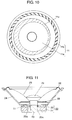
- Fig. 11 is a cross-sectional view of a conventional speaker showing a construction of the speaker.
- the conventional speaker includes lower plate 20, magnet 21, upper plate 22, frame 24, diaphragm 25, edge 26, voice coil 27, dumper 28, and dust cap 29.
- Lower plate 20 is made of magnetic material, and pole 20a is formed at a center of lower plate 20.
- Magnet 21 is formed in a ring shape.
- a magnet for a speaker application is generally made of a material of neodymium group or of ferrite group, as magnet 21.
- Upper plate 22 is also formed in a ring shape and is made of magnetic material.
- Upper plate 22, magnet 21 and lower plate 20 constitute magnetic circuit 23.
- Magnetic gap 23a is formed in a ring shape between a peripheral wall of pole 20a of lower plate 20 and an inner peripheral wall of upper plate 22.
- Frame 24 is bonded with upper plate 22 at a center of frame 24.
- Diaphragm 25 is bonded through edge 26 to a peripheral edge of frame 24 at a outer peripheral part of diaphragm 25, and an inner peripheral part of the diaphragm 25 is bonded with voice coil 27 placed in magnetic gap 23a in a freely movable manner.
- Damper 28 is bonded with voice coil 27 at an inner peripheral part of damper 28, and an outer peripheral part of damper 28 is bonded with frame 24, thus supporting voice coil 27.
- Dust cap 29 is a dust-roofing cover attached to an upper center part of diaphragm 25.
- diaphragm 25 is made lighter in weight by reducing a thickness of material or by using a material in a low density.
- diaphragm 25 which is made lighter in this way has lower modulus of elasticity, causing a split resonance of diaphragm 25, or causing a resonance of edge 26 bonded with the outer peripheral part of diaphragm 25.
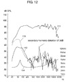
- Fig. 12 exemplarily shows graphical data indicating a frequency characteristic of a conventional speaker.
- a unit of a vertical axis which indicates a sound pressure characteristic 111, second-harmonic distortion characteristic 112 and third-harmonic distortion characteristic 113, is in dB SPL (Sound Pressure Level).
- a unit of a vertical axis, which indicates impedance characteristic 114, is in ohm.
- the characteristic of a sound pressure level versus frequency is sometimes called a SPL characteristic, hereinafter.
- the present invention provides a speaker realizing both light in weight and high sound quality at one time.
- the speaker of the present invention includes a magnetic circuit, a frame and a diaphragm.
- the magnetic circuit has a magnetic gap in a ring shape.
- the frame is bonded with the magnetic circuit at a central part of the frame.
- the diaphragm is bonded with a voice coil placed in the magnetic gap in a freely movable manner at a central part of the diaphragm, and the outer peripheral part of the diaphragm is bonded with a peripheral edge of the frame through an edge.
- An external shape of the edge bonded with the outer peripheral part of the diaphragm is formed in a perfect circle, and at least one of the outer peripheral part of the diaphragm and an inner peripheral part of the edge, which becomes a mutual bonding portion, is formed in a different shape than the perfect circle.
- This constitution controls split resonance, thereby providing a speaker which realizes both the light in weight and high sound quality.
- One other speaker includes a magnetic circuit, a frame and a diaphragm.
- the magnetic circuit has a magnetic gap in a ring shape.
- the frame is bonded with the magnetic circuit at a central part of the frame.
- the diaphragm is bonded with a voice coil placed in the magnetic gap in a freely movable manner at a central part of the diaphragm, and the outer peripheral part of the diaphragm is bonded with a peripheral edge of the frame through an edge.
- An internal shape and an external shape of the edge, and an external shape of the diaphragm are formed in a perfect circle respectively.
- the diaphragm and the edge can be overlaid with respective center shifted each other and are bonded together.
- the split resonance is further controlled, thereby providing a speaker achieving both a light in weight and high sound quality.
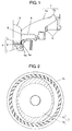
- Fig. 1 is a half sectional view for showing a structure of a speaker in accordance with the first exemplary embodiment of the present invention.
- the speaker as shown in Fig. 1 includes yoke 1, magnet 2, top plate 3, frame 5, voice coil 6, diaphragm 7, damper 8 and dust cap 9.
- Yoke 1 is made of magnetic material, with its bottom central portion protruded upward.
- Yoke 1 has an external wall in a cylindrical shape.
- Magnet 2 is in a disk shape and is generally made of a material of ferrite group or of neodymium group.
- Top plate 3 is made of magnetic material and formed in a disk shape.
- Yoke 1, magnet 2 and top plate 3 are overlaid and bonded together, constituting magnetic circuit 4.
- Magnetic gap 4a is formed in a ring shape between yoke 1 and top plate 3, between an inner peripheral side of the cylindrical wall of the yoke 1 and an outer peripheral side of the top plate 3.
- Frame 5 is made of resin. Magnetic circuit 4 is attached to a center of frame 5. More concretely, frame 5 is bonded with yoke 1 with an adhesive, otherwise yoke 1 can be press-fit to frame 5. Yoke 1 can also be fit into frame 5 by an already known method such as outsert-molding. Voice coil 6 is placed in magnetic gap 4a in a freely movable manner where magnetic circuit 4 is formed with coil portion 6a.
- Diaphragm 7 is composed of diaphragm main body 7a in a cone shape and edge 7b in a ring shape, details of which are described later. Edge 7 is attached to an outer peripheral part of diaphragm main body 7a. Damper 8 is attached to voice coil 6 at an inner peripheral part of damper 8. Damper 8 is attached to frame 5 at an outer peripheral part of damper 8. So damper 8 sustains voice coil 6. Dust cap 9 is a dust-proofing cap attached to an upper center part of diaphragm 7.
- Fig. 2 is a plan view of diaphragm 7 of the speaker in accordance with the present exemplary embodiment, viewed from a rear side.
- edge 7b is attached to the outer peripheral part of diaphragm main body 7a, with forming a ring shape.
- Edge 7b is formed in a substantially perfect circle both in the inner peripheral part and the outer peripheral part.
- the word of the perfect circle includes a substantially perfect circle, hereinafter.
- the outer peripheral part of diaphragm main body 7a is formed in an oval shape.
- the outer peripheral part of diaphragm 7a formed in the oval shape and the inner peripheral part of edge 7b formed in the perfect circle are overlaid and bonded together at bonding portion 7c, a hatched portion of the drawing.
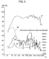
- Fig. 3 is a characteristic diagram of the sound pressure vs. frequency of a 16 cm bore diameter speaker manufactured in accordance with the exemplary embodiment of the present invention.
- the speaker in accordance with the exemplary embodiment of the present invention second-harmonic distortion derived from the natural resonance is reduced by about 7 dB than a conventional speaker, because the natural resonance of edge 7b is controlled.
- edge 7b is formed in a perfect circle both in the outer peripheral part and the inner peripheral part, that the outer peripheral part of diaphragm main body 7a is formed in an oval shape, and that the outer peripheral part of diaphragm 7a formed in the oval shape and the inner peripheral part of edge 7b formed in the perfect circle are overlaid and bonded together.
- the present invention is not limited to this case. As long as the outer peripheral part of edge 7b is formed in a perfect circle, one of the outer peripheral part of diaphragm main body 7a and the inner peripheral part of edge 7b, which becomes the bonding part of the other, can be formed in a different shape than the perfect circle.
- Fig. 4 is a plan view of diaphragm 7 of a speaker in accordance with the exemplary embodiment of the present invention, viewed from a rear side.
- An outer peripheral part of diaphragm main body 7a is formed in a perfect circle, then the outer peripheral part of diaphragm main body 7a formed in the perfect circle and an inner peripheral part of edge 7b formed in a pentagon shape are overlaid and bonded together. Because the natural resonance of edge 7b is caused at distorted frequencies of even number, much preferable shape of edge 7b is either an oval or an odd number polygon.
- a speaker in accordance with the second exemplary embodiment in the present invention is different from the first exemplary embodiment in a structure of the diaphragm. Structure other than the diaphragm is the same as that of the first exemplary embodiment, so the same numerical reference is given to an identical part and its detailed explanation is omitted. Below, only different parts are explained using the drawings.
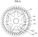
- Fig. 5 is a plan view of a diaphragm to be used for the exemplary embodiment of the present invention.
- diaphragm 10 is composed of diaphragm main body 10a in a cone shape and edge 10b in a ring shape.
- Edge 10b is bonded with an outer peripheral part of diaphragm main body 10a.
- Edge 10b is formed in a perfect circle both in an outer peripheral part and an inner peripheral part thereof.
- the outer peripheral part of diaphragm main body 10a is formed in an oval shape.
- the outer peripheral part of diaphragm main body 10a formed in the oval shape and an inner peripheral part of edge 10b formed in the perfect circle are overlaid and bonded together at bonding portion 10c.
- This structure is the same as the one in the first exemplary embodiment.
- Diaphragm main body 10a includes thick portion 10d, quasi-thick portion 10e and thin portion 10f. Seven thick portions 10d are extended radially from a central part of diaphragm main body 10a with a substantially same angle between each other. Quasi-thick portion 10e is formed between radially extended thick portions 10d and its thickness is becoming thinner as it goes from outer peripheral part toward the center of diaphragm main body 10a. Thin portion 10f is formed in substantially web-like shape toward an inner side of quasi-thick portion 10e. Above described, diaphragm main body 10a is similar to the diaphragm which the inventors of this invention claimed for a patent in Japanese Patent Application No. 2003-354832 .
- diaphragm 10 is so constituted that new effects are added to the first exemplary embodiment.
- thick portion 10d disposed in odd number prevents a line-symmetric portion to be formed in diaphragm main body 10a.
- quasi-thick portion 10e enforces bending rigidity of diaphragm main body 10a from the central part toward an outer direction, preventing a split resonance to be caused at a natural resonance mode.
- Split resonance which is caused along the peripheral part by the natural resonance mode is also prevented by quasi-thick portion 10e.
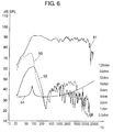
- Fig, 6 is a characteristic diagram showing a frequency characteristic of a 16 cm bore diameter speaker manufactured in accordance with the exemplary embodiment.
- edge 10b The natural resonance of edge 10b is controlled differently depending on how oval diaphragm main body 10a is formed.
- the difference in the control depends on how thick portion 10d, quasi-thick portion 10e and thin portion 10f are disposed, when the outer peripheral part of diaphragm main body 10a formed in the oval shape and the inner peripheral part of edge 10b formed in a perfect circle are overlaid and bonded together.
- sound characteristic can be arbitrarily controlled. Such difference is explained in Fig. 7 to Fig. 9.
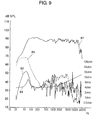
- Figs. 7 to 9 are characteristic diagrams showing a frequency characteristic of a speaker in accordance with the second exemplary embodiment of the present invention. They indicate SPL characteristics of a case in which the inner peripheral part of edge 10b formed into a perfect circle and the outer peripheral part of diaphragm main body 10a formed into an oval shape are bonded together.
- Fig. 7 indicates a SPL characteristic of a speaker in which thick potion 10d is disposed along a longer diameter of the oval shape.
- Fig. 8 indicates a SPL characteristic of a speaker in which a middle part of thick portion 10d and quasi-thick portion 10e is disposed along the longer diameter of the oval.
- Fig. 9 indicates a SPL characteristic of a speaker in-between one of Fig. 7 and one of Fig. 8.
- the speaker having the characteristic shown in Fig. 8 in which the middle part of thick portion 10d and quasi-thick portion 10e is disposed along the longer diameter of the oval causes little larger second-harmonic distortion derived from the natural resonance of edge 10b as compared with Fig. 7.
- a frequency band where a sound pressure level falls down due to natural resonance of edge 10b, so-called "a midrange valley” can be narrowed. Consequently, bits fall of musical information can be most effectively minimized, enabling the speaker to reproduce the original sound in high fidelity.
- thick portion 10d and quasi-thick portion 10e are disposed at the rear side of diaphragm 10. As in this arrangement, by not having an uneven front surface on diaphragm 10 of thick portion 10d and quasi-thick portion 10e, phase disturbance of an acoustic wave caused by vibration of diaphragm 10 can be prevented.
- the speaker in accordance with the third exemplary embodiment is different from the speaker in the first exemplary embodiment in a structure of a diaphragm.
- Other structure is identical to that of the first exemplary embodiment, so that a same numerical reference is used for the identical part and detailed explanation of it is omitted. Below, only different parts are explained using the drawing.
- Fig. 10 is a plan view of a diaphragm used for a speaker in accordance with the third exemplary embodiment, viewed from a rear side.
- diaphragm 11 is composed of diaphragm main body 11 a in a cone shape and edge 11 b formed in a ring shape.
- Edge 11 b is attached to an outer peripheral part of diaphragm main body 11 a.
- Edge 11 b is formed in a perfect circle both in an inner peripheral part and an outer peripheral part, which is the same as that of the first exemplary embodiment.
- Diaphragm main body 11a is also shaped in a perfect circle shape in its outer peripheral part.
- the outer peripheral part of diaphragm main body 11a formed in the perfect circle and the inner peripheral part of edge 11 b formed in the perfect circle are overlaid except for each center shifted from the other, and both are bonded together at bonding portion 11c.
- the shape of the diaphragm including the edge becomes partially asymmetric, similar to the cases where the outer peripheral part of the diaphragm main body is formed into a shape other than the perfect circle in the first and the second exemplary embodiments.
- specific frequency derived from the natural resonance of the edge is made different.
- the split resonance of the diaphragm can also be controlled similarly with the second exemplary embodiment, if thick portions and quasi-thick portions in odd-number are disposed onto the diaphragm, and if the thin-portions in the web-like shape are further added to the rear side of diaphragm main body 11a.
- the speaker according to the present invention can control a split resonance of a diaphragm main body and a natural resonance of an edge, therewith providing a good sound pressure versus frequency characteristic, namely a high sound quality.
- the speaker is useful for a variety of electronic devices including an audio instrument and an in-car acoustic device.
Landscapes
- Engineering & Computer Science (AREA)
- Multimedia (AREA)
- Physics & Mathematics (AREA)
- Acoustics & Sound (AREA)
- Signal Processing (AREA)
- Diaphragms For Electromechanical Transducers (AREA)
- Audible-Bandwidth Dynamoelectric Transducers Other Than Pickups (AREA)
Applications Claiming Priority (2)
| Application Number | Priority Date | Filing Date | Title |
|---|---|---|---|
| JP2004157394A JP4228998B2 (ja) | 2004-05-27 | 2004-05-27 | スピーカ |
| PCT/JP2005/009225 WO2005117488A1 (fr) | 2004-05-27 | 2005-05-20 | Haut-parleur |
Publications (2)
| Publication Number | Publication Date |
|---|---|
| EP1742502A1 true EP1742502A1 (fr) | 2007-01-10 |
| EP1742502A4 EP1742502A4 (fr) | 2010-08-04 |
Family
ID=35451296
Family Applications (1)
| Application Number | Title | Priority Date | Filing Date |
|---|---|---|---|
| EP05741576A Withdrawn EP1742502A4 (fr) | 2004-05-27 | 2005-05-20 | Haut-parleur |
Country Status (6)
| Country | Link |
|---|---|
| US (1) | US7899204B2 (fr) |
| EP (1) | EP1742502A4 (fr) |
| JP (1) | JP4228998B2 (fr) |
| CN (1) | CN1951149B (fr) |
| TW (1) | TW200601870A (fr) |
| WO (1) | WO2005117488A1 (fr) |
Cited By (1)
| Publication number | Priority date | Publication date | Assignee | Title |
|---|---|---|---|---|
| US7899204B2 (en) | 2004-05-27 | 2011-03-01 | Panasonic Corporation | Speaker |
Families Citing this family (8)
| Publication number | Priority date | Publication date | Assignee | Title |
|---|---|---|---|---|
| US8090139B2 (en) * | 2005-06-29 | 2012-01-03 | Benjamin Reinecke | Diaphragm for an electroacoustic transducer, and electroacoustic transducer |
| JP4658087B2 (ja) * | 2007-04-18 | 2011-03-23 | パイオニア株式会社 | スピーカ用エッジおよびスピーカ装置 |
| JP4867774B2 (ja) * | 2007-04-26 | 2012-02-01 | パナソニック株式会社 | スピーカ |
| JP2011091645A (ja) * | 2009-10-22 | 2011-05-06 | Sony Corp | スピーカ振動板及びスピーカ装置 |
| JP2012138887A (ja) * | 2010-12-08 | 2012-07-19 | Panasonic Corp | 振動板、およびそれを備えたスピーカー装置 |
| JP5626461B2 (ja) * | 2011-05-11 | 2014-11-19 | パナソニック株式会社 | 映像表示装置 |
| JP6275297B1 (ja) * | 2017-01-31 | 2018-02-07 | アルパイン株式会社 | 音響装置 |
| JP7255047B2 (ja) | 2018-09-18 | 2023-04-11 | フォスター電機株式会社 | スピーカ用振動板 |
Family Cites Families (15)
| Publication number | Priority date | Publication date | Assignee | Title |
|---|---|---|---|---|
| GB1270033A (en) | 1968-11-19 | 1972-04-12 | Nippon Musical Instruments Mfg | Louspeaker |
| JPS50130421A (fr) * | 1974-02-28 | 1975-10-15 | ||
| FR2282203A1 (fr) | 1974-08-12 | 1976-03-12 | Rehde Weber | Haut-parleur |
| US4881617A (en) * | 1988-12-30 | 1989-11-21 | Alexander Faraone | Radially arcuated speaker cone |
| DK110993D0 (da) | 1993-10-04 | 1993-10-04 | Vifa Speak As | Hoejttaler |
| JPH07162992A (ja) | 1993-12-06 | 1995-06-23 | Sharp Corp | スピーカ振動板 |
| JP3992876B2 (ja) * | 1998-05-08 | 2007-10-17 | 松下電器産業株式会社 | スピーカ |
| EP0963136B1 (fr) * | 1998-05-08 | 2011-08-31 | Panasonic Corporation | Haut-parleur |
| JP2000092591A (ja) | 1998-09-11 | 2000-03-31 | Sharp Corp | スピーカ用エッジ |
| JP3508834B2 (ja) * | 1999-04-22 | 2004-03-22 | 株式会社ケンウッド | スピーカ振動板 |
| US6567529B1 (en) | 2000-12-29 | 2003-05-20 | Mitek Corporation | Low frequency loudspeaker driver having a polygonal diaphragm and method for mounting drivers in a tightly packed two-dimensional array |
| JP4386327B2 (ja) | 2002-03-04 | 2009-12-16 | パイオニア株式会社 | スピーカ装置 |
| US7054459B2 (en) * | 2002-05-17 | 2006-05-30 | Matsushita Electric Industrial Co., Ltd. | Surrounding structure of a loudspeaker |
| JP4407229B2 (ja) | 2003-10-15 | 2010-02-03 | パナソニック株式会社 | スピーカ用振動板およびこれを用いたスピーカ |
| JP4228998B2 (ja) | 2004-05-27 | 2009-02-25 | パナソニック株式会社 | スピーカ |
-
2004
- 2004-05-27 JP JP2004157394A patent/JP4228998B2/ja not_active Expired - Lifetime
-
2005
- 2005-05-20 TW TW094116552A patent/TW200601870A/zh unknown
- 2005-05-20 EP EP05741576A patent/EP1742502A4/fr not_active Withdrawn
- 2005-05-20 US US11/569,384 patent/US7899204B2/en active Active
- 2005-05-20 CN CN2005800141672A patent/CN1951149B/zh not_active Expired - Lifetime
- 2005-05-20 WO PCT/JP2005/009225 patent/WO2005117488A1/fr not_active Ceased
Cited By (1)
| Publication number | Priority date | Publication date | Assignee | Title |
|---|---|---|---|---|
| US7899204B2 (en) | 2004-05-27 | 2011-03-01 | Panasonic Corporation | Speaker |
Also Published As
| Publication number | Publication date |
|---|---|
| EP1742502A4 (fr) | 2010-08-04 |
| WO2005117488A1 (fr) | 2005-12-08 |
| US7899204B2 (en) | 2011-03-01 |
| CN1951149B (zh) | 2012-06-27 |
| CN1951149A (zh) | 2007-04-18 |
| JP4228998B2 (ja) | 2009-02-25 |
| TW200601870A (en) | 2006-01-01 |
| US20070183619A1 (en) | 2007-08-09 |
| JP2005341223A (ja) | 2005-12-08 |
Similar Documents
| Publication | Publication Date | Title |
|---|---|---|
| JP4743793B2 (ja) | スピーカー振動板およびこれを用いたスピーカー | |
| US9654881B2 (en) | Electroacoustic transducer | |
| US20160157020A1 (en) | Electroacoustic transducer | |
| US7899204B2 (en) | Speaker | |
| JP4407229B2 (ja) | スピーカ用振動板およびこれを用いたスピーカ | |
| CN1843057B (zh) | 扬声器 | |
| JP2004260736A (ja) | スピーカ装置 | |
| CN112840675B (zh) | 扬声器用振动板 | |
| US8428298B2 (en) | Damper for speaker and speaker using the damper | |
| EP1708542B1 (fr) | Diaphragme et haut-parleur utilisant celui-ci | |
| JPH05316590A (ja) | 楕円形スピーカ | |
| JP2005167384A (ja) | スピーカ装置 | |
| JPH10322795A (ja) | スピーカ装置 | |
| JP4413119B2 (ja) | スピーカ | |
| JP2012109691A (ja) | ヘッドホン | |
| CN107623888A (zh) | 电声转换装置 | |
| JPH0937385A (ja) | コーン型スピーカ | |
| JP2006014138A (ja) | スピーカ用振動板及びこれを用いたスピーカ | |
| JPH03213098A (ja) | スピーカ | |
| JPH0795686A (ja) | スピーカユニット | |
| JP2006261737A (ja) | スピーカ | |
| JP2006020124A (ja) | スピーカ | |
| JP2009135858A (ja) | スピーカ | |
| JPH09312897A (ja) | 電気音響変換器 | |
| CN108141671A (zh) | 扬声器 |
Legal Events
| Date | Code | Title | Description |
|---|---|---|---|
| PUAI | Public reference made under article 153(3) epc to a published international application that has entered the european phase |
Free format text: ORIGINAL CODE: 0009012 |
|
| 17P | Request for examination filed |
Effective date: 20061116 |
|
| AK | Designated contracting states |
Kind code of ref document: A1 Designated state(s): DE FR GB |
|
| RBV | Designated contracting states (corrected) |
Designated state(s): DE FR GB |
|
| DAX | Request for extension of the european patent (deleted) | ||
| RBV | Designated contracting states (corrected) |
Designated state(s): DE FR GB |
|
| RAP1 | Party data changed (applicant data changed or rights of an application transferred) |
Owner name: PANASONIC CORPORATION |
|
| A4 | Supplementary search report drawn up and despatched |
Effective date: 20100705 |
|
| RIC1 | Information provided on ipc code assigned before grant |
Ipc: H04R 7/14 20060101ALI20100629BHEP Ipc: H04R 7/20 20060101AFI20051215BHEP |
|
| STAA | Information on the status of an ep patent application or granted ep patent |
Free format text: STATUS: THE APPLICATION HAS BEEN WITHDRAWN |
|
| 18W | Application withdrawn |
Effective date: 20110131 |