EP1743563A2 - Staubsauger - Google Patents
Staubsauger Download PDFInfo
- Publication number
- EP1743563A2 EP1743563A2 EP06014619A EP06014619A EP1743563A2 EP 1743563 A2 EP1743563 A2 EP 1743563A2 EP 06014619 A EP06014619 A EP 06014619A EP 06014619 A EP06014619 A EP 06014619A EP 1743563 A2 EP1743563 A2 EP 1743563A2
- Authority
- EP
- European Patent Office
- Prior art keywords
- vacuum cleaner
- electric blower
- input
- input level
- level
- Prior art date
- Legal status (The legal status is an assumption and is not a legal conclusion. Google has not performed a legal analysis and makes no representation as to the accuracy of the status listed.)
- Withdrawn
Links
Images




Classifications
-
- A—HUMAN NECESSITIES
- A47—FURNITURE; DOMESTIC ARTICLES OR APPLIANCES; COFFEE MILLS; SPICE MILLS; SUCTION CLEANERS IN GENERAL
- A47L—DOMESTIC WASHING OR CLEANING; SUCTION CLEANERS IN GENERAL
- A47L5/00—Structural features of suction cleaners
- A47L5/12—Structural features of suction cleaners with power-driven air-pumps or air-compressors, e.g. driven by motor vehicle engine vacuum
- A47L5/22—Structural features of suction cleaners with power-driven air-pumps or air-compressors, e.g. driven by motor vehicle engine vacuum with rotary fans
-
- A—HUMAN NECESSITIES
- A47—FURNITURE; DOMESTIC ARTICLES OR APPLIANCES; COFFEE MILLS; SPICE MILLS; SUCTION CLEANERS IN GENERAL
- A47L—DOMESTIC WASHING OR CLEANING; SUCTION CLEANERS IN GENERAL
- A47L9/00—Details or accessories of suction cleaners, e.g. mechanical means for controlling the suction or for effecting pulsating action; Storing devices specially adapted to suction cleaners or parts thereof; Carrying-vehicles specially adapted for suction cleaners
- A47L9/22—Mountings for motor fan assemblies
-
- A—HUMAN NECESSITIES
- A47—FURNITURE; DOMESTIC ARTICLES OR APPLIANCES; COFFEE MILLS; SPICE MILLS; SUCTION CLEANERS IN GENERAL
- A47L—DOMESTIC WASHING OR CLEANING; SUCTION CLEANERS IN GENERAL
- A47L9/00—Details or accessories of suction cleaners, e.g. mechanical means for controlling the suction or for effecting pulsating action; Storing devices specially adapted to suction cleaners or parts thereof; Carrying-vehicles specially adapted for suction cleaners
- A47L9/28—Installation of the electric equipment, e.g. adaptation or attachment to the suction cleaner; Controlling suction cleaners by electric means
- A47L9/2836—Installation of the electric equipment, e.g. adaptation or attachment to the suction cleaner; Controlling suction cleaners by electric means characterised by the parts which are controlled
- A47L9/2842—Suction motors or blowers
Definitions
- the present invention relates to a high-input vacuum cleaner featuring a high input (high maximum power consumption) required especially in Europe, Asia such as China, the Middle and Near East and so forth, and also capable of allowing a user to vary an input thereof depending on circumstances, thus providing a high usability.
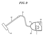
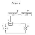
- vacuum cleaner 30 includes volume or slide type input control unit 52 for adjusting an operation input as desired depending on circumstances; electric blower 1 for generating a suction force; main controller 37 for controlling an operational status of electric blower 1; and triac 36 for performing a phase control of electric blower 1.
- Electric blower 1 has a motor and a fan unit.
- Electric blower 1 has two input terminals, one of which is connected to one side of commercial power supply via triac 36, while the other is connected to the other side of commercial power supply 55.
- Main controller 37 adjusts a conduction phase angle for turning on triac 37 for performing a phase control thereof according to a set value of input control unit 52, so that the electric power supplied to electric blower 1 is controlled at a desired power level.
- vacuum cleaner 30 capable of operating in a wide range of the input levels, not just limited to the maximum input level, because if it can be operated only at the maximum level, the usability thereof would become restricted.
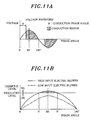
- a phase control of triac 36 is performed to control electric blower 1 as illustrated in Fig. 11A, during which a phase angle ⁇ for turning on electric blower 1 is adjusted, whereby a power supplied to electric blower 1 is changed.
- Fig. 11A shows a relationship between a phase angle and a harmonic level generated in response thereto.
- the harmonic level is highest at the phase angle of about 90°, and when the phase angle changes from 90° to 0° (or from 90° to 180°), the harmonic level decreases.
- an electric blower whose maximum input level is high causes a relatively high harmonic level
- an electric blower whose maximum input level is low causes a relatively low harmonic level.
- the harmonic level is governed by local regulations.
- the harmonic level generated by a vacuum cleaner does not satisfy the regulations, it cannot be put on the local market as a product.
- the electric blower is operated within an operation range where its phase angle is close to 90° (i.e., within a range from X° to Y° shown in Fig. 11B)
- the harmonic level generated in response thereto would exceed a regulated level, although there may be some exceptions depending on the type of the electric blower.
- the harmonic level increases, and it is strictly required to fall within the regulated level in the entire range of the input levels. Accordingly, in the conventional vacuum cleaner, the input level can be varied only within a range corresponding to the phase angles except for the range from X° to Y°, as shown in Figs. 12A and 12B.
- Reference 1 Disclosed in, for example, Japanese Patent Laid-open Application No. S63-274396 (Reference 1) is a method for implementing a high-input vacuum cleaner capable of suppressing harmonic currents below a regulated level by employing an input control method of alternating a phase angle for controlling an electric blower between a small and a large value periodically.
- Reference 1 As a side effect of driving the electric blower through the control method described in Reference 1, vibrations and noises of the electric blower are increased, which, in turn, increases vibration of the main body of the vacuum cleaner, making it difficult for the user to use.
- an object of the present invention to provide a high-input vacuum cleaner whose maximum input is not smaller than about 1600 W as required in the market and whose input level can be adjusted as desired within the entire range smaller than or equal to the maximum input level.
- a vacuum cleaner in accordance with the present invention includes a first and a second electric blower for generating a suction force, wherein a sum of maximum input levels or maximum power consumptions of the first and the second electric blower is set to be about 1600 W or greater.
- a vacuum cleaner including a first and a second electric blower for generating a suction force, wherein a sum of maximum input levels or maximum power consumptions of the first and the second electric blower is set to be about 1600 W or greater.
- the vacuum cleaner is operable at a high input level higher than or equal to about 1600 W, and the input adjustment value covers an entire input range, thereby implementing a high suction performance of the vacuum cleaner.
- respective suction inlets of the first and the second electric blower are respectively communicated with a dust chamber of a vacuum cleaner main body, and the first and the second electric blower are installed in parallel to each other in an air duct of the vacuum cleaner.
- the vacuum cleaner is operable at a high input level higher than or equal to about 1600 W, and the input adjustment value covers an entire input range, thereby implementing a high suction performance of the vacuum cleaner.
- a suction inlet of the first electric blower is communicated with a dust chamber of a vacuum cleaner main body while a suction inlet of the second electric blower is communicated with an air exhaust side of the first electric blower, and the first and the second electric blower are installed in series in an air duct of the vacuum cleaner.
- the vacuum cleaner is operable at a high input level higher than or equal to about 1600 W, and the input adjustment value covers an entire input range, thereby implementing a high suction performance of the vacuum cleaner especially through a high vacuum level.
- the vacuum cleaner further includes a first controller for controlling the first electric blower; a second controller for controlling the second electric blower; an input setting unit; a commercial power supply; and a main control unit for controlling the first and the second controller in response to a signal from the input setting unit, wherein the first electric blower and the second electric blower are connected to the commercial power supply via the first controller and the second controller, respectively.
- the vacuum cleaner is operable at a high input level higher than or equal to about 1600 W, and the input adjustment value covers an entire input range, thereby implementing a high suction performance of the vacuum cleaner especially through a high vacuum level.
- an operation input is adjusted to a desired input level by means of an input setting unit in such a manner that the vacuum cleaner is operable at any input level ranging from the minimum input level to the maximum input level, wherein, if the operation input falls within a range from a minimum input level to about 1/2 of a maximum input level, ⁇ 2 is maintained at about 180° and the second electric power is not turned on whereas ⁇ 1 is controlled between about 180° to about 0° inclusive such that the vacuum cleaner is operated at the desired input level, and if the operation input falls with in a range from about 1/2 of the maximum input level to the maximum input level, ⁇ 1 is maintained at about 0° and the first electric blower is operated in a fully conducting state whereas ⁇ 2 is controlled between about 180° to about 0° inclusive such that the vacuum cleaner is operated at the desired input level, and wherein ⁇ 1 and ⁇ 2 designate phase angles for turning on the first and the second electric blower, respectively, and are controlled by the first and the second controller, respectively.
- the vacuum cleaner is
- an operation input is adjusted to a desired input level by means of an input setting unit in such a manner that the vacuum cleaner is operable at any input level ranging from the minimum input level to the maximum input level, wherein the first and the second electric blower are operated at respective phase angles of ⁇ 1 and ⁇ 2, and the main control unit controls the first and the second controller to obtain specific values of ⁇ 1 and ⁇ 2 at which a sum of power supply harmonics generated as a result of operating the first and the second electric blowers does not exceed a predetermined level, through which control mechanism, and wherein ⁇ 1 and ⁇ 2 designate phase angles for turning on the first and the second electric blower, respectively, and are controlled by the first and the second controller, respectively.
- the vacuum cleaner is operable at a high input level higher than or equal to about 1600 W, and the input adjustment value covers an entire input range, thereby implementing a high suction performance of the vacuum cleaner especially through a high vacuum level.
- Fig. 1 is a schematic view of a vacuum cleaner in accordance with a first preferred embodiment of the present invention
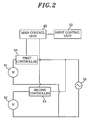
- Fig. 2 sets forth a circuit block diagram of the vacuum cleaner
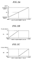
- Fig. 3A shows an input level as a function of an input adjustment value of the vacuum cleaner
- Fig. 3B describes a phase angle for turning on a first electric blower as a function of the input adjustment value of the vacuum cleaner
- Fig. 3C depicts a phase angle for turning on a second electric blower as a function of the input adjustment value of the vacuum cleaner.
- vacuum cleaner 10 includes first electric blower 61 and second electric blower 62.
- the sum of maximum power consumptions of first and second electric blower 61 and 62 is equal to or greater than about 1600 W. That is, the maximum power consumption of vacuum cleaner is equal to or greater than about 1600 W.
- Suction inlets of electric blowers 61 and 62 are respectively communicated with dust chamber 11 of electric blower 30.
- first electric blower 61 and second electric blower 62 are phase-controlled by first controller 63 and second controller 64, respectively.
- First and second controllers performs a phase control by adjusting phase angles for turning on first electric blower 61 and second electric blower and 62, respectively, based on commands from main control unit 65 indicating conduction phase angles of the electric blowers, wherein the conduction phase angles are defined as phase angles for turning on the electric blowers.
- Main control unit 65 controls the operation of vacuum cleaner 10 in compliance with an input adjustment value set by a user manipulating input control unit 52.
- a user would operate the vacuum cleaner by setting an input level of the vacuum cleaner within an operable input range from a minimum input level to a maximum input level. If the input set by the user is within a range less than or equal to 1/2 of the maximum input level, no power is supplied to second electric blower 62 (i.e., its conduction phase angle is set to be 180°), and first electric blower 61 is operated by setting its conduction phase angle such that the desired input level is obtained.
- first electric blower 61 is set to be in a fully conducting state (i.e., its conduction phase angle is set to be 0°), and second electric blower 62 is operated by setting its conduction phase angle such that the desired input level is obtained.
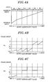
- Fig. 4A shows an input level as a function of an input adjustment value of the vacuum cleaner in accordance with a second preferred embodiment of the present invention
- Fig. 4B describes a phase angle for turning on a first electric blower as a function of the input adjustment value of the vacuum cleaner in accordance with the second embodiment of the present invention
- Fig. 4C depicts a phase angle for turning on a second electric blower as a function of the input adjustment value of the vacuum cleaner in accordance with the second embodiment of the present invention.
- a user would operate the vacuum cleaner by setting an input for the vacuum cleaner within an operable input range from a minimum input level to a maximum input level. If the vacuum cleaner is operated, desired powers are supplied to both of first electric blower 61 and second electric blower 62.
- ⁇ 1 and ⁇ 2 respectively designate the conduction phase angles of first and second electric blower 61 and 62 that are respectively controlled by first controller 63 and second controller 64, and let X° and Y° designate specific phase angles satisfying the condition that the sum of the harmonics generated by the two electric blowers does not exceed a regulated level with a range from X° to Y°.
- the input adjustment value and the operational statuses of electric blowers 61 and 62 are controlled by a preset conduction pattern.
- One example of the conduction pattern is illustrated in Figs. 4A to 4C.
- the range from the minimum input level to the maximum input level is first divided into six input regions: a first region including the minimum input level to a sixth region including the maximum input level.
- both of the electric blowers are powered on even at a minimum input level.
- Both ⁇ 1 and ⁇ 2 decrease as an input adjustment value increases, and the first region ends when ⁇ 1 and ⁇ 2 reach about 1/2 of X°.
- ⁇ 1 returns to 180°
- ⁇ 2 is set to be X°.
- ⁇ 1 gradually decreases starting from 180° while ⁇ 2 remaining constant, and the second region ends when ⁇ 1 reaches X°.
- ⁇ 1 returns to 180° and ⁇ 2 is set to be Y°.
- ⁇ 1 gradually decreases starting from 180° while ⁇ 2 remaining constant, and the third region ends when ⁇ 1 reaches X° again as in the second region.
- ⁇ 1 returns to 180°, and ⁇ 2 is set to be 0°.
- ⁇ 1 gradually decreases starting from 180° while ⁇ 2 remaining constant, and the fourth region ends when ⁇ 1 reaches X° again, as in the second region.
- both ⁇ 1 and ⁇ 2 are set to be Y°.
- ⁇ 1 gradually decreases starting from Y° while ⁇ 2 remaining constant, and the fifth region ends when ⁇ 1 reaches 0°.
- ⁇ 1 returns to Y° and ⁇ 2 is set to be 0°.
- ⁇ 1 decreases starting from Y° while ⁇ 2 remaining constant, and the sixth region ends when ⁇ 1 reaches 0° again as in the fifth region.
- vacuum cleaner 10' includes first electric blower 61 and second electric blower 62.
- the suction inlet of first electric blower 61 is communicated with dust chamber 11 of vacuum cleaner 10', and second electric blower 62 is disposed downstream of first electric blower 61.
- First and second electric blower 61 and 62 are controlled by the same control mechanism as described in the first or the second preferred embodiment.
- the vacuum pressure of the vacuum cleaner can be increased.
- a high-input vacuum cleaner featuring a high-dust collecting capacity can be provided.
- a fourth preferred embodiment of the present invention will be descried with reference to Figs. 6 to 8. Parts identical to those of the conventional example will be assigned same reference numerals, and their description will be omitted.
- Fig. 6 depicts a schematic view of a vacuum cleaner in accordance with a fourth preferred embodiment of the present invention
- Fig. 7 illustrates a circuit block diagram of the vacuum cleaner in accordance with the fourth preferred embodiment of the present invention
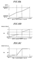
- Fig. 8A shows an input level as a function of an input adjustment value of the vacuum cleaner in accordance with a fourth preferred embodiment of the present invention
- Fig. 8B describes a phase angle for turning on a first electric blower as a function of the input adjustment value of the vacuum cleaner in accordance with the fourth embodiment of the present invention
- Fig. 8C depicts a phase angle for turning on a second electric blower as a function of the input adjustment value of the vacuum cleaner in accordance with the fourth embodiment of the present invention
- vacuum cleaner 10" includes: dust chamber 11; electric blower 71 installed to communicate with dust chamber; hose 41 connected to dust chamber 11; extension line 42; and bottom nozzle 48.
- Bottom nozzle 48 has: rotation brush 44 for scraping up dusts on a floor to thereby facilitate dust collection; and driving unit 72 for driving rotation brush 44.
- An output side of driving unit 72 and rotation brush 44 are connected with each other via belt 45 serving as a motive power transfer means.
- the maximum power consumption of electric blower 71 is equal to or greater than about 1500 W
- the maximum power consumption of driving unit 72 is equal to or greater than about 100 W, making the maximum power consumption of vacuum cleaner 10" to be about 1600 W or greater.
- electric blower 71 is phase-controlled by first controller 73
- driving unit 72 is phase-controlled by second controller 74.
- First and second controller 73 and 74 execute the phase controls of electric blower 71 and driving unit 72 in response to commands from main control unit 75 indicating conduction phase angles of electric blower 71 and driving unit 72, respectively.
- Main control unit 75 controls the operation of vacuum cleaner 10" in compliance with an input adjustment value set by a user by means of input control unit 52.
- vacuum cleaner 10 having the above configuration.
- a user would operate the vacuum cleaner by setting an input within an operable input range from a minimum input level to a maximum input level.
- a conduction phase angle ⁇ 3 of electric blower 71 controlled by first controller 73 gradually decreases starting from 180°.
- a conduction phase angle ⁇ 4 of driving unit 72 controlled by second controller 74 is maintained at Z° that is lower than a phase angle for a fully conducting state (i.e., 180° in this case).
- ⁇ 3 gradually decreases to reach a phase angle X° at which the power supply harmonic level exceeds a regulated level, and ⁇ 4 remains constant.
- ⁇ 3 is maintained at X°, and ⁇ 4 is decreased from Z° to 0° in response to the input adjustment value. If the input adjustment value of vacuum cleaner 10'' is further increased after ⁇ 3 reaches 0°, ⁇ 3 is set to be Y°, and ⁇ 4 is maintained at 0°. If the input adjustment value of vacuum cleaner 10" is further increased after that, ⁇ 3 is gradually decreased from Y° to 0°.
- the vacuum cleaner can be operated within the entire input range from the minimum input level to the maximum input level.
- the vacuum cleaner in accordance with the present invention as described above is a high-input vacuum cleaner operable within a wide operation input range lower than or equal to a maximum input level. Thus, the usability of the vacuum cleaner can be improved.
- the vacuum cleaner in accordance with the present invention is operable at a high input level, and further, at any input level within an entire input range from a minimum input level to a maximum input level, so that it can meet local regulations while allowing a high power consumption and a variable input level, thereby improving the usability.
Landscapes
- Engineering & Computer Science (AREA)
- Mechanical Engineering (AREA)
- Electric Vacuum Cleaner (AREA)
- Filters For Electric Vacuum Cleaners (AREA)
Applications Claiming Priority (1)
| Application Number | Priority Date | Filing Date | Title |
|---|---|---|---|
| JP2005205269A JP2007020765A (ja) | 2005-07-14 | 2005-07-14 | 電気掃除機 |
Publications (2)
| Publication Number | Publication Date |
|---|---|
| EP1743563A2 true EP1743563A2 (de) | 2007-01-17 |
| EP1743563A3 EP1743563A3 (de) | 2007-03-07 |
Family
ID=37101574
Family Applications (1)
| Application Number | Title | Priority Date | Filing Date |
|---|---|---|---|
| EP06014619A Withdrawn EP1743563A3 (de) | 2005-07-14 | 2006-07-13 | Staubsauger |
Country Status (3)
| Country | Link |
|---|---|
| EP (1) | EP1743563A3 (de) |
| JP (1) | JP2007020765A (de) |
| CN (1) | CN1895142A (de) |
Cited By (3)
| Publication number | Priority date | Publication date | Assignee | Title |
|---|---|---|---|---|
| EP2211678A4 (de) * | 2007-11-26 | 2012-08-22 | Toshiba Kk | Elektrischer staubsauger |
| RU2468736C1 (ru) * | 2008-10-31 | 2012-12-10 | Кабусики Кайся Тосиба | Электрический пылесос |
| WO2022128102A1 (en) * | 2020-12-17 | 2022-06-23 | Aktiebolaget Electrolux | Vacuum cleaner |
Families Citing this family (5)
| Publication number | Priority date | Publication date | Assignee | Title |
|---|---|---|---|---|
| JP2010104692A (ja) * | 2008-10-31 | 2010-05-13 | Toshiba Corp | 電気掃除機 |
| JP2011030776A (ja) * | 2009-07-31 | 2011-02-17 | Toshiba Corp | 電気掃除機およびその調整方法 |
| JP2012090733A (ja) * | 2010-10-26 | 2012-05-17 | Toshiba Corp | 電気掃除機 |
| JP5758188B2 (ja) * | 2011-04-28 | 2015-08-05 | 株式会社東芝 | 電気掃除機 |
| JP6101551B2 (ja) * | 2013-04-26 | 2017-03-22 | 日立アプライアンス株式会社 | 家庭用電気掃除機 |
Family Cites Families (3)
| Publication number | Priority date | Publication date | Assignee | Title |
|---|---|---|---|---|
| BE528468A (de) * | 1953-05-04 | |||
| US5920953A (en) * | 1997-07-21 | 1999-07-13 | Windsor Industries, Inc. | Carpet and upholstery cleaner/extractor |
| DE19802711C2 (de) * | 1998-01-24 | 2003-06-05 | Wap Reinigungssysteme | Leistungsreduzierung einer Doppelturbine in Schmutzsaugern |
-
2005
- 2005-07-14 JP JP2005205269A patent/JP2007020765A/ja active Pending
-
2006
- 2006-07-13 EP EP06014619A patent/EP1743563A3/de not_active Withdrawn
- 2006-07-14 CN CNA2006101055276A patent/CN1895142A/zh active Pending
Cited By (4)
| Publication number | Priority date | Publication date | Assignee | Title |
|---|---|---|---|---|
| EP2211678A4 (de) * | 2007-11-26 | 2012-08-22 | Toshiba Kk | Elektrischer staubsauger |
| RU2468736C1 (ru) * | 2008-10-31 | 2012-12-10 | Кабусики Кайся Тосиба | Электрический пылесос |
| WO2022128102A1 (en) * | 2020-12-17 | 2022-06-23 | Aktiebolaget Electrolux | Vacuum cleaner |
| US12557950B2 (en) | 2020-12-17 | 2026-02-24 | Aktiebolaget Electrolux | Vacuum cleaner |
Also Published As
| Publication number | Publication date |
|---|---|
| EP1743563A3 (de) | 2007-03-07 |
| JP2007020765A (ja) | 2007-02-01 |
| CN1895142A (zh) | 2007-01-17 |
Similar Documents
| Publication | Publication Date | Title |
|---|---|---|
| US8607402B2 (en) | Vacuum cleaner with a vacuum cleaner fan | |
| JP5983928B2 (ja) | 電動作業機 | |
| US7698777B2 (en) | Vacuum cleaner | |
| JP2010503505A (ja) | モータ駆動装置 | |
| CN107708513B (zh) | 清洁器 | |
| CA2300341C (en) | Wall-mounted microwave oven and method for controlling hood motor therefor | |
| CN108903808A (zh) | 一种电机无级调速方法、装置及手持吸尘器 | |
| US7102326B1 (en) | Motor speed variator and a driving method thereof | |
| CN112994534A (zh) | 一种无刷直流电机控制方法、装置、无刷直流电机及电器 | |
| JP2000257871A (ja) | 壁掛け型電子レンジ及びそのフードモータの速度制御方法 | |
| JP2005013460A (ja) | 充電式電気掃除機 | |
| CN100566642C (zh) | 电真空吸尘器 | |
| JP2007020765A (ja) | 電気掃除機 | |
| JP6130152B2 (ja) | レンジフード | |
| JP4946681B2 (ja) | 電気掃除機 | |
| CN102450983B (zh) | 电动吸尘器 | |
| JP2001016894A (ja) | 電気機器ならびに電気掃除機 | |
| JP2015054155A (ja) | 電気掃除機 | |
| JP2992303B2 (ja) | 電気掃除機 | |
| JP4128205B2 (ja) | 電気掃除機 | |
| JPH10192209A (ja) | 電気掃除機 | |
| JP2003135342A (ja) | 電気掃除機 | |
| JP5070176B2 (ja) | 電気掃除機 | |
| JP2020018412A (ja) | クリーナ | |
| JP6397533B2 (ja) | レンジフード |
Legal Events
| Date | Code | Title | Description |
|---|---|---|---|
| PUAI | Public reference made under article 153(3) epc to a published international application that has entered the european phase |
Free format text: ORIGINAL CODE: 0009012 |
|
| AK | Designated contracting states |
Kind code of ref document: A2 Designated state(s): AT BE BG CH CY CZ DE DK EE ES FI FR GB GR HU IE IS IT LI LT LU LV MC NL PL PT RO SE SI SK TR |
|
| AX | Request for extension of the european patent |
Extension state: AL BA HR MK YU |
|
| PUAL | Search report despatched |
Free format text: ORIGINAL CODE: 0009013 |
|
| AK | Designated contracting states |
Kind code of ref document: A3 Designated state(s): AT BE BG CH CY CZ DE DK EE ES FI FR GB GR HU IE IS IT LI LT LU LV MC NL PL PT RO SE SI SK TR |
|
| AX | Request for extension of the european patent |
Extension state: AL BA HR MK YU |
|
| RIC1 | Information provided on ipc code assigned before grant |
Ipc: A47L 9/28 20060101ALI20070126BHEP Ipc: H02P 5/00 20060101ALI20070126BHEP Ipc: A47L 5/22 20060101ALI20070126BHEP Ipc: A47L 9/22 20060101AFI20061023BHEP |
|
| AKX | Designation fees paid | ||
| STAA | Information on the status of an ep patent application or granted ep patent |
Free format text: STATUS: THE APPLICATION IS DEEMED TO BE WITHDRAWN |
|
| 18D | Application deemed to be withdrawn |
Effective date: 20070908 |
|
| REG | Reference to a national code |
Ref country code: DE Ref legal event code: 8566 |