EP1744016A1 - Elément de carénage pour gaz chauds, chemise de protection de l'arbre et turbine à gaz - Google Patents
Elément de carénage pour gaz chauds, chemise de protection de l'arbre et turbine à gaz Download PDFInfo
- Publication number
- EP1744016A1 EP1744016A1 EP05015001A EP05015001A EP1744016A1 EP 1744016 A1 EP1744016 A1 EP 1744016A1 EP 05015001 A EP05015001 A EP 05015001A EP 05015001 A EP05015001 A EP 05015001A EP 1744016 A1 EP1744016 A1 EP 1744016A1
- Authority
- EP
- European Patent Office
- Prior art keywords
- hot gas
- turbine
- housing
- inner housing
- gas
- Prior art date
- Legal status (The legal status is an assumption and is not a legal conclusion. Google has not performed a legal analysis and makes no representation as to the accuracy of the status listed.)
- Withdrawn
Links
- 239000012809 cooling fluid Substances 0.000 claims abstract description 44
- 230000001681 protective effect Effects 0.000 claims abstract description 14
- 238000002485 combustion reaction Methods 0.000 claims description 20
- 230000002093 peripheral effect Effects 0.000 claims description 14
- 238000000576 coating method Methods 0.000 claims description 9
- 239000011248 coating agent Substances 0.000 claims description 6
- 230000002401 inhibitory effect Effects 0.000 claims description 6
- 230000007797 corrosion Effects 0.000 claims description 4
- 238000005260 corrosion Methods 0.000 claims description 4
- 230000003647 oxidation Effects 0.000 claims description 4
- 238000007254 oxidation reaction Methods 0.000 claims description 4
- 239000007789 gas Substances 0.000 description 64
- 238000001816 cooling Methods 0.000 description 12
- 230000005855 radiation Effects 0.000 description 11
- 230000000694 effects Effects 0.000 description 4
- 239000012720 thermal barrier coating Substances 0.000 description 4
- PXHVJJICTQNCMI-UHFFFAOYSA-N Nickel Chemical compound [Ni] PXHVJJICTQNCMI-UHFFFAOYSA-N 0.000 description 3
- 239000000567 combustion gas Substances 0.000 description 3
- 238000005336 cracking Methods 0.000 description 3
- 239000000463 material Substances 0.000 description 3
- 239000003570 air Substances 0.000 description 2
- 230000004888 barrier function Effects 0.000 description 2
- 239000000446 fuel Substances 0.000 description 2
- 238000007689 inspection Methods 0.000 description 2
- XEEYBQQBJWHFJM-UHFFFAOYSA-N Iron Chemical compound [Fe] XEEYBQQBJWHFJM-UHFFFAOYSA-N 0.000 description 1
- 229910045601 alloy Inorganic materials 0.000 description 1
- 239000000956 alloy Substances 0.000 description 1
- 239000012080 ambient air Substances 0.000 description 1
- 230000015572 biosynthetic process Effects 0.000 description 1
- 229910017052 cobalt Inorganic materials 0.000 description 1
- 239000010941 cobalt Substances 0.000 description 1
- GUTLYIVDDKVIGB-UHFFFAOYSA-N cobalt atom Chemical compound [Co] GUTLYIVDDKVIGB-UHFFFAOYSA-N 0.000 description 1
- 230000007547 defect Effects 0.000 description 1
- 230000001419 dependent effect Effects 0.000 description 1
- 229910052735 hafnium Inorganic materials 0.000 description 1
- VBJZVLUMGGDVMO-UHFFFAOYSA-N hafnium atom Chemical compound [Hf] VBJZVLUMGGDVMO-UHFFFAOYSA-N 0.000 description 1
- 238000010438 heat treatment Methods 0.000 description 1
- 238000009434 installation Methods 0.000 description 1
- 229910052759 nickel Inorganic materials 0.000 description 1
- 229910052761 rare earth metal Inorganic materials 0.000 description 1
- 238000000926 separation method Methods 0.000 description 1
- 229910052710 silicon Inorganic materials 0.000 description 1
- 239000010703 silicon Substances 0.000 description 1
- 125000006850 spacer group Chemical group 0.000 description 1
- 229910001233 yttria-stabilized zirconia Inorganic materials 0.000 description 1
- 229910052727 yttrium Inorganic materials 0.000 description 1
- VWQVUPCCIRVNHF-UHFFFAOYSA-N yttrium atom Chemical compound [Y] VWQVUPCCIRVNHF-UHFFFAOYSA-N 0.000 description 1
Images


Classifications
-
- F—MECHANICAL ENGINEERING; LIGHTING; HEATING; WEAPONS; BLASTING
- F23—COMBUSTION APPARATUS; COMBUSTION PROCESSES
- F23R—GENERATING COMBUSTION PRODUCTS OF HIGH PRESSURE OR HIGH VELOCITY, e.g. GAS-TURBINE COMBUSTION CHAMBERS
- F23R3/00—Continuous combustion chambers using liquid or gaseous fuel
- F23R3/42—Continuous combustion chambers using liquid or gaseous fuel characterised by the arrangement or form of the flame tubes or combustion chambers
- F23R3/60—Support structures; Attaching or mounting means
-
- F—MECHANICAL ENGINEERING; LIGHTING; HEATING; WEAPONS; BLASTING
- F01—MACHINES OR ENGINES IN GENERAL; ENGINE PLANTS IN GENERAL; STEAM ENGINES
- F01D—NON-POSITIVE DISPLACEMENT MACHINES OR ENGINES, e.g. STEAM TURBINES
- F01D25/00—Component parts, details, or accessories, not provided for in, or of interest apart from, other groups
- F01D25/08—Cooling; Heating; Heat-insulation
- F01D25/12—Cooling
-
- F—MECHANICAL ENGINEERING; LIGHTING; HEATING; WEAPONS; BLASTING
- F01—MACHINES OR ENGINES IN GENERAL; ENGINE PLANTS IN GENERAL; STEAM ENGINES
- F01D—NON-POSITIVE DISPLACEMENT MACHINES OR ENGINES, e.g. STEAM TURBINES
- F01D25/00—Component parts, details, or accessories, not provided for in, or of interest apart from, other groups
- F01D25/08—Cooling; Heating; Heat-insulation
- F01D25/14—Casings modified therefor
-
- F—MECHANICAL ENGINEERING; LIGHTING; HEATING; WEAPONS; BLASTING
- F01—MACHINES OR ENGINES IN GENERAL; ENGINE PLANTS IN GENERAL; STEAM ENGINES
- F01D—NON-POSITIVE DISPLACEMENT MACHINES OR ENGINES, e.g. STEAM TURBINES
- F01D5/00—Blades; Blade-carrying members; Heating, heat-insulating, cooling or antivibration means on the blades or the members
- F01D5/02—Blade-carrying members, e.g. rotors
- F01D5/08—Heating, heat-insulating or cooling means
-
- F—MECHANICAL ENGINEERING; LIGHTING; HEATING; WEAPONS; BLASTING
- F05—INDEXING SCHEMES RELATING TO ENGINES OR PUMPS IN VARIOUS SUBCLASSES OF CLASSES F01-F04
- F05D—INDEXING SCHEME FOR ASPECTS RELATING TO NON-POSITIVE-DISPLACEMENT MACHINES OR ENGINES, GAS-TURBINES OR JET-PROPULSION PLANTS
- F05D2250/00—Geometry
- F05D2250/20—Three-dimensional
- F05D2250/23—Three-dimensional prismatic
- F05D2250/231—Three-dimensional prismatic cylindrical
-
- F—MECHANICAL ENGINEERING; LIGHTING; HEATING; WEAPONS; BLASTING
- F05—INDEXING SCHEMES RELATING TO ENGINES OR PUMPS IN VARIOUS SUBCLASSES OF CLASSES F01-F04
- F05D—INDEXING SCHEME FOR ASPECTS RELATING TO NON-POSITIVE-DISPLACEMENT MACHINES OR ENGINES, GAS-TURBINES OR JET-PROPULSION PLANTS
- F05D2260/00—Function
- F05D2260/20—Heat transfer, e.g. cooling
- F05D2260/201—Heat transfer, e.g. cooling by impingement of a fluid
-
- F—MECHANICAL ENGINEERING; LIGHTING; HEATING; WEAPONS; BLASTING
- F05—INDEXING SCHEMES RELATING TO ENGINES OR PUMPS IN VARIOUS SUBCLASSES OF CLASSES F01-F04
- F05D—INDEXING SCHEME FOR ASPECTS RELATING TO NON-POSITIVE-DISPLACEMENT MACHINES OR ENGINES, GAS-TURBINES OR JET-PROPULSION PLANTS
- F05D2260/00—Function
- F05D2260/20—Heat transfer, e.g. cooling
- F05D2260/202—Heat transfer, e.g. cooling by film cooling
-
- F—MECHANICAL ENGINEERING; LIGHTING; HEATING; WEAPONS; BLASTING
- F23—COMBUSTION APPARATUS; COMBUSTION PROCESSES
- F23R—GENERATING COMBUSTION PRODUCTS OF HIGH PRESSURE OR HIGH VELOCITY, e.g. GAS-TURBINE COMBUSTION CHAMBERS
- F23R2900/00—Special features of, or arrangements for continuous combustion chambers; Combustion processes therefor
- F23R2900/03044—Impingement cooled combustion chamber walls or subassemblies
Definitions
- the present invention relates to a hot gas-carrying housing element for a hot gas-carrying housing, which can be arranged in particular in a gas turbine plant around a turbine rotor of the gas turbine plant around and serves to guide a hot gas to a turbine part of the gas turbine plant. Moreover, the present invention relates to a wave protection jacket of the hot gas-carrying housing, which is designed to surround the turbine rotor of the gas turbine plant. Finally, the present invention relates to the hot gas-carrying housing itself and a gas turbine plant with a hot gas-carrying housing.
- a gas turbine plant 1 essentially comprises one or more combustion chambers 3 (see Fig. 1), in which a fuel is burned, a turbine 5, the hot and pressurized combustion exhaust gases from the combustion chambers 3 are supplied and in the exhaust gases below Cooling and relaxation work and so put the turbine 5 in rotation, and a compressor 7, which is coupled to the turbine 5 via a shaft 15 and through which the necessary air for combustion is sucked and compressed to a higher pressure.
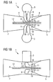
- FIG. 1 shows such a gas turbine plant in a schematic view, wherein Fig.1a show a horizontal and Fig. 1b shows a vertical section through the system. From these Silobrennhuntn 3 flow the combustion gases 2 in one Direction, which is substantially perpendicular to the axis of rotation A of the turbine 5. Between the outlet 18 of the silo combustion chambers and the turbine 5, a mixing housing 8 is arranged, which is followed by an inner housing 9 arranged in the interior of the gas turbine housing 2 on the turbine side.
- the inner housing 9 has the task to protect the surrounding components from heat and to redirect the emerging from the mixing housing 8 hot gases in the direction of the turbine.
- the combustion exhaust gases When exiting the inner housing 9, that is to say when entering the turbine 5 of the gas turbine plant 1, the combustion exhaust gases then flow essentially parallel to the axis of rotation A of the turbine shaft 12.
- Hot gas-carrying housing, and in particular the described inner housing in gas turbine plants with Silobrennhuntn represent thermally highly stressed components. For this reason, measures are taken for cooling the hot gas bearing surfaces of the housing. These measures include the cooling of the particularly stressed areas by means of a cooling fluid which flows along the outside of the walls of these areas in order to absorb and dissipate the heat transferred to the hot gas-conducting surfaces.
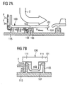
- the inner housing hub 101 surrounds a shaft protection jacket 115 (FIG. 7 a), which in turn surrounds the shaft 12.
- the housing interior facing surface 109, the inner housing hub 101, the guide and guide surface for the combustion gases 2 while the housing interior facing away from surface 104 of the inner housing hub 101 surrounds the wave protection casing 115.
- the inner housing hub 101 is fixed to the shaft protection casing 115 by means of an annular rib 103, which is arranged centrally in the axial direction and protrudes toward the wave protection casing 115.
- the shaft protection casing 115 itself is fastened to the gas turbine casing 2 and has a web 105 with an annular groove 106 arranged therein in which the annular rib 103 engages.
- Inner housing hub 101 and wave protection jacket 115 are installed together as a unit in the gas turbine plant.
- the web 105 has passage openings 107 through which the cooling fluid can flow (see Figures 7a and 7b).
- the rib 103 experiences less heating during operation of the hot gas-carrying housing than the material regions located closer to the hot gas-carrying surface 109 of the cylindrical inner housing hub 101. This leads to a so-called barrel tire effect, which leads to stresses in the material regions of the inner housing hub 101 which adjoin the rib 103. In particular, at the designated by the reference numeral 111 locations may therefore cause cracks in the material.
- the rib has been moved into the area of the turbine-side opening of the inner housing, so that it is located in a thermally less heavily loaded area of the inner housing.
- Another object of the present invention is to provide a wave protection jacket for a hot gas-carrying housing of a Gas turbine plant to provide, which allows improved fixing of a hot gas-carrying housing element.
- Yet another object of the present invention is to provide an improved housing unit for a gas turbine plant.
- the first object is achieved by a hot gas-conducting housing element according to claim 1, the second object by a wave protection jacket according to claim 8, the third object by a housing unit according to claim 9 and the fourth object by a gas turbine plant according to claim 11.
- the dependent claims contain advantageous embodiments of the invention.
- a hot gas-conducting housing element for a hot gas-carrying housing of a gas turbine plant having a compressor, a turbine and a turbine rotor is designed to surround a wave protection jacket to be arranged around the turbine rotor and to guide a hot gas to the turbine. It comprises at least one hot gas inlet opening, a turbine-side opening and a guide section for guiding the hot gas from the at least one hot gas inlet opening to the turbine-side opening.
- the guide section has an inner housing hub designed to surround the shaft protection casing of the gas turbine plant, which extends up to the turbine-side opening and has a circumferential surface extending completely or partially along the peripheral surface and protruding beyond the circumferential surface on the protective shaft jacket.
- the inner housing hub may at least approximately have a cylindrical shape and in particular have the shape of a hollow cylinder, wherein the shaft protection jacket peripheral surface to be facing then represents the inner surface of the hollow cylinder.
- a rib is disposed in the region of the peripheral surface adjacent to the turbine-side opening.
- the rib is provided with cooling fluid channels.
- the inner housing hub is provided at least in the region of the rib with cooling fluid channels.
- the location of the rib in that portion of the peripheral surface of the inner housing hub adjacent to the turbine-side opening allows for substantially undisturbed flow of cooling fluid along the inner housing hub to the turbine-side opening, which already improves the opportunities for cooling the inner housing hub.
- the arrangement according to the invention of the cooling fluid channels now also makes it possible to improve the possibility of cooling in the region of the rib by reducing the barrier effect of the rib or improving the guidance of the cooling fluid in the region of the rib.
- the rib is provided with cooling fluid passages which allow passage of the cooling fluid through the rib, the barrier effect for cooling fluid flow can be reduced.
- the flow of the cooling fluid is particularly little disturbed when these cooling fluid passages are arranged in the rib so that they run near the peripheral surface of the inner housing hub adjacent parallel to its axial direction.
- the inner housing hub is provided with cooling fluid channels.
- These can, for example, in each case have a protective shaft-side opening, that is to say an opening in the peripheral surface facing the wave protection jacket, and a hot-gas-side opening, that is to say an opening in the surface guiding the hot gas.
- a protective shaft-side opening that is to say an opening in the peripheral surface facing the wave protection jacket
- a hot-gas-side opening that is to say an opening in the surface guiding the hot gas.
- the formation of a cooling fluid film on the hot gas side surface of the inner housing hub is possible when the cooling fluid passages extend in their course through the inner housing hub from the protective shaft side opening seen, which represents an inlet opening for the cooling fluid, having an inclination in the flow direction of the hot gas to be led.
- cooling fluid ducts may also be present which run parallel to the hot gas-conducting surface of the inner housing hub between an inlet opening for the inlet of the cooling fluid and an outlet opening for outlet of the cooling fluid.
- Such cooling fluid channels allow a particularly effective cooling of the inner housing hub.
- a hot gas-conducting surface and in particular the inner housing hub can be provided with a heat-insulating and / or corrosion-inhibiting and / or oxidation-inhibiting coating.
- a shaft protection jacket according to the invention for a gas turbine plant having a compressor, a turbine and a turbine rotor is designed to surround the turbine rotor in the region between the compressor and the turbine of the gas turbine plant and has a recess extending in the circumferential direction wholly or partly over its circumference for receiving a rib of a to be arranged around the wave protection jacket around hot gas-conducting housing element of the hot gas-conducting housing.
- the recess is in a fully closed radially over the peripheral surface, i. no cooling fluid channels having web arranged.
- a hot gas-carrying housing element can be fixed by inserting the rib in the recess of the wave protection jacket.
- the web can in this case, for example, act as a spacer between the shaft protection casing and the inner housing hub of a hot gas-conducting housing element, so that between the inner housing hub and the wave protection jacket remains a gap which can be traversed by a cooling fluid.
- a housing unit according to the invention comprises a hot gas-carrying housing with a hot gas-conducting housing element according to the invention and a wave protection jacket according to the invention.
- the hot gas-carrying housing may in this case be designed in particular as an inner housing for a gas turbine plant with at least one silo combustion chamber.
- a gas turbine plant according to the invention comprises at least one combustion chamber, a turbine part and a hot gas-carrying housing according to the invention arranged between the at least one combustion chamber and the turbine part for guiding the hot gas from the at least one combustion chamber to the turbine part.
- the gas turbine plant according to the invention may in particular comprise at least one silo combustion chamber and a mixing housing arranged between the silo combustion chamber and the hot gas carrying housing.
- the hot gas-carrying housing is then designed as an inner casing of the gas turbine plant.
- FIGS. 1a and 1b An example of gas turbine installation 1 is shown in FIGS. 1a and 1b in a highly schematic representation.
- the gas turbine plant 1 comprises two silo combustion chambers 3, a turbine 5, a compressor 7, two mixing housings 8 and an inner housing 9.
- the silo combustion chambers 3 serve to burn a fuel, the hot exhaust gases 2 under high pressure being supplied via the mixing housings 8 and the inner housing 9 of the turbine 7 are supplied to drive them.
- the turbine 5 comprises stationary guide vanes 10 and rotor blades 11 fixedly connected to a shaft 12 rotatably mounted about an axis A.
- the hot exhaust gas 2 expanding in the turbine 5 causes impulse to flow via the rotor blades 11 transferred to the shaft 12, whereby it is set in rotation.
- the shaft 12 can be roughly divided into three sections, namely a section carrying the rotor blades 11 of the turbine 5, a rotor blade of the compressor 7 (not shown) and a shaft section 13 arranged between these two sections, in which no rotor blades are arranged.
- the shaft 12 and the attached blades 11 form the so-called. Turbine rotor.
- the shaft 12 extends through the entire gas turbine plant (not fully shown) and drives the compressor 7 and a generator, not shown.
- the compressor 7 serves to compress air, which is then fed to the silo combustion chambers 3 for combustion.
- the shaft section 13 is surrounded by a shaft protection casing 15 (see Fig. 2), which itself is surrounded by an inner housing hub 17 of a hot gas-carrying housing element 6 of the inner housing 9.
- Inner housing 9 and shaft protection jacket 15 are installed together as a housing unit in the gas turbine plant.
- the inner housing hub 17 and the shaft protection jacket 15 have substantially the shape of a hollow cylinder, wherein the shaft protection jacket 15 facing peripheral surface 14 of the inner housing hub 17 and the turbine rotor facing surface of the wave protection jacket 15 form the inner surfaces of the hollow cylinder.
- the inner housing 9 serves to deflect the hot exhaust flowing from the mixing housings 8 into the inner housing 9 on the one hand and to distribute it as evenly as possible around the entire circumference of the turbine runner on the other hand. It serves the Hot gas facing surface 20 of the inner housing 9 as a guide and guide surface for the hot gas.
- This can in particular also be provided with a heat-insulating coating or a corrosion and / or oxidation-inhibiting coating.
- a heat-insulating coating for example, so-called thermal barrier coatings, TBC for short, in question, which may be made of yttria stabilized zirconia about.
- MCrAlY coatings As corrosion and / or oxidation-inhibiting coatings, for example, so-called MCrAlY coatings in question, where M for iron (Fe), cobalt (Co) or nickel (Ni) and Y for yttrium (Y) and / or silicon and / or a Rare earth elements, such as hafnium (Hf).
- M for iron (Fe), cobalt (Co) or nickel (Ni) and Y for yttrium (Y) and / or silicon and / or a Rare earth elements, such as hafnium (Hf).
- Such alloys are known inter alia from the following documents, to which reference is made for suitable MCrAlY coatings: EP 0 486 489 B1 . EP 0 786 017 B1 . EP 0 412 397 B1 and EP 1 306 454 A1 .
- the thermal barrier coating TBC can in this case be applied in particular to the MCrAlY coating
- FIG. 2 shows a detail from FIG. 1b, in which the inner housing hub 17 of the inner housing 9 as well as a part of the wave protection jacket 15 can be seen.
- a guide vane 10 of the turbine 5 can be seen, which is opposite to the turbine-side opening 19 of the inner housing 9.
- the inner housing hub 17 of the inner housing 9 has in the region of the turbine-side opening 19 a radially projecting in the direction of the wave protection jacket 15 annular rib 22 which extends over its entire circumference.
- the wave protection jacket 15 comprises an annular web 23 which extends in the region of the outlet opening 19 of the inner housing 9 over the entire circumference of the wave protection jacket 15.
- the web 23 has a groove 26 which serves to receive the rib 22 of the inner housing hub 17.
- By means of the rib 22 and the groove 26 in the web 23 can be the mecanicgephaseenabe 17 of the hot gas-conducting housing element 6 fix on the shaft protection jacket 15.
- the wave protection jacket 15 also has a radiation protection 16, which surrounds him at a distance. Between the radiation protection 16 and the wave protection jacket 15, a flow channel is thus formed. A further flow channel is formed between the radiation protection 16 and the inner housing hub 17 of the hot gas-conducting housing element 6.
- the radiation shield 16 has passage openings 21 for the passage of the cooling fluid in the direction of the inner housing hub 17, which serve for supplying a cooling fluid F, for example ambient air, into the flow channel between the radiation shield 16 and the inner housing hub 17 (see FIG. 3).
- the cooling fluid passing through the openings 21 is used for impingement cooling of the inner housing hub 17 and forwarded to the turbine 5 via the flow channel 24 formed between the radiation protection 16 and the inner housing hub 17, in which case a convective cooling of the inner housing hub 17 takes place.
- impingement cooling is here to be understood the supply of cooling fluid, which has such a flow direction that it bounces against the hub side surface 14 of the inner housing hub 17 and is deflected by this.
- an interior housing 9 of the prior art is first described with reference to Figure 3, in which the rib of the hot gas-carrying housing member 6 is located in the region of the turbine-side opening of the inner housing 9. Thereafter, with reference to the figures 4 to 6 inner housing 9 is described with three different embodiments of the hot gas-conducting housing element 6 according to the invention.
- the state of the art and all variants have an inner housing hub 17, 17a, 17b, 17c, which are each provided in the region of the turbine-side opening with a rib 22, 22a, 22b, 22c protruding beyond the protective surface on the outer circumferential surface 14, 14a, 14b, 14c.
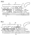
- FIG. 3 An embodiment of the inner housing hub 17, the radiation protection 16 and the wave protection jacket 15 in the region of the rib 22 and the web 23 according to the prior art is shown in Fig. 3.
- the web 23 below the groove 26 through holes 25 in the form of holes available, which allow passage of the cooling fluid (indicated by arrows) through the web 23.
- the output end of the through hole 25 in the flow direction opposite a guide rib 38 is arranged on the shaft protection casing 15, which leads to a deflection of the cooling fluid flow in the direction of the gas flowing through the gas turbine plant hot exhaust gas.
- FIG. 1 A first embodiment variant of the hot gas-carrying housing element 6 is shown in FIG.
- the figure shows the inner housing hub 17a, the radiation protection 16a and the wave protection jacket 15a in the region of the web 23a.
- the web 23a of the wave protection mantle 15a of FIG. 4 differs from the web 23 of the wave protection mantle 15 of FIG. 3 in that it is wider and does not protrude so far beyond the surface 20a of the wave protection mantle 15a.
- it has no through hole for the passage of a cooling fluid.
- a passage opening in the form of a bore 25a is arranged in the rib 22a of the inner housing hub 17a, which allows the passage of the cooling fluid through the rib 22a.
- the through hole is arranged in the immediate vicinity of the shaft protection jacket 15a facing peripheral surface 14a of the inner housing hub 17a. Corresponding through holes are spaced apart from one another in the circumferential direction over the entire annular rib 22a.
- FIG. 5 A second embodiment for the embodiment of the hot gas-carrying housing element 6 is shown in Fig. 5.
- the figure shows the inner housing hub 17b, the radiation protection 16 and the wave protection jacket 15 in the region of the web 23.
- the wave protection jacket 15 and the radiation protection 16 have the same configuration as the corresponding parts of the embodiment described with reference to FIG. 3.
- the inner housing hub 17b in the second embodiment variant has passage openings in the form of through-holes 28 with openings 29 on the outer side of the protective shaft and hot-gas-side openings 30.
- the hot gas side openings 30 are thereby displaced in the flow direction of the hot gas in comparison to the wave protection jacket side openings 29.
- the openings 29 have an inclination in the flow direction of the hot exhaust gases, viewed from the circumferential surface 14b of the protective shaft on the side of the protective shaft.
- cooling fluid enters through the through-holes 28 from the flow channel 24 into the region of the inner housing 9 carrying the hot exhaust gas and forms a cooling fluid film over the hot-gas-side surface 20b of the inner housing hub 17b, in particular in the region of the rib 22b.
- This embodiment of the inner housing hub 17b allows a highly effective cooling of the surface 20b.
- FIG. 6 A third embodiment of the hot gas-carrying housing element 6 is shown in Fig. 6.
- the figure shows the inner housing hub 17c, the radiation protection 16 and the wave protection jacket 15 in the region of the web 23.
- the inner housing hub 17c through holes in the form of holes 28c on.
- These bores 28c each have a protective shaft side opening 29c and an opening 30c arranged in the end face of the inner housing hub 17c. Between the protective shaft-side opening 29c and the front-side opening 30c, each through-hole 28c extends largely parallel to the hot-gas-conducting surface 20c of the inner housing hub 17c.
- the web of the wave protection jacket is provided with passage openings for the passage of cooling fluid.
Landscapes
- Engineering & Computer Science (AREA)
- Mechanical Engineering (AREA)
- General Engineering & Computer Science (AREA)
- Chemical & Material Sciences (AREA)
- Combustion & Propulsion (AREA)
- Turbine Rotor Nozzle Sealing (AREA)
Priority Applications (8)
| Application Number | Priority Date | Filing Date | Title |
|---|---|---|---|
| EP05015001A EP1744016A1 (fr) | 2005-07-11 | 2005-07-11 | Elément de carénage pour gaz chauds, chemise de protection de l'arbre et turbine à gaz |
| RU2008104922/06A RU2425227C2 (ru) | 2005-07-11 | 2006-07-04 | Внутренний корпус для газотурбинной установки, защитная оболочка вала, блок корпуса для газотурбинной установки и газотурбинная установка |
| AU2006268716A AU2006268716B2 (en) | 2005-07-11 | 2006-07-04 | Hot gas-conducting housing element, protective shaft jacket, and gas turbine system |
| CN2006800251817A CN101218416B (zh) | 2005-07-11 | 2006-07-04 | 导引热燃气的机匣元件、轴保护套和燃气轮机装置 |
| PCT/EP2006/063825 WO2007006680A2 (fr) | 2005-07-11 | 2006-07-04 | Element de carter conducteur de gaz chaud, enveloppe de protection d'arbre et systeme de turbine a gaz |
| US11/988,709 US8147179B2 (en) | 2005-07-11 | 2006-07-04 | Hot-gas-ducting housing element, protective shaft jacket and gas turbine system |
| EP06764031A EP1904717B1 (fr) | 2005-07-11 | 2006-07-04 | Element de carter conducteur de gaz chaud, enveloppe de protection d'arbre et systeme de turbine a gaz |
| ZA200800182A ZA200800182B (en) | 2005-07-11 | 2008-01-08 | Hot gas-conducting housing element, protective shaft jacket, and gas turbine system |
Applications Claiming Priority (1)
| Application Number | Priority Date | Filing Date | Title |
|---|---|---|---|
| EP05015001A EP1744016A1 (fr) | 2005-07-11 | 2005-07-11 | Elément de carénage pour gaz chauds, chemise de protection de l'arbre et turbine à gaz |
Publications (1)
| Publication Number | Publication Date |
|---|---|
| EP1744016A1 true EP1744016A1 (fr) | 2007-01-17 |
Family
ID=35197780
Family Applications (2)
| Application Number | Title | Priority Date | Filing Date |
|---|---|---|---|
| EP05015001A Withdrawn EP1744016A1 (fr) | 2005-07-11 | 2005-07-11 | Elément de carénage pour gaz chauds, chemise de protection de l'arbre et turbine à gaz |
| EP06764031A Active EP1904717B1 (fr) | 2005-07-11 | 2006-07-04 | Element de carter conducteur de gaz chaud, enveloppe de protection d'arbre et systeme de turbine a gaz |
Family Applications After (1)
| Application Number | Title | Priority Date | Filing Date |
|---|---|---|---|
| EP06764031A Active EP1904717B1 (fr) | 2005-07-11 | 2006-07-04 | Element de carter conducteur de gaz chaud, enveloppe de protection d'arbre et systeme de turbine a gaz |
Country Status (7)
| Country | Link |
|---|---|
| US (1) | US8147179B2 (fr) |
| EP (2) | EP1744016A1 (fr) |
| CN (1) | CN101218416B (fr) |
| AU (1) | AU2006268716B2 (fr) |
| RU (1) | RU2425227C2 (fr) |
| WO (1) | WO2007006680A2 (fr) |
| ZA (1) | ZA200800182B (fr) |
Cited By (2)
| Publication number | Priority date | Publication date | Assignee | Title |
|---|---|---|---|---|
| WO2013110765A1 (fr) * | 2012-01-26 | 2013-08-01 | Energy Intelligence Lab Gmbh | Carter de turbine et de générateur refroidi en plusieurs parties |
| WO2015044266A1 (fr) * | 2013-09-27 | 2015-04-02 | Siemens Aktiengesellschaft | Moyeu de boîtier intérieur pour une turbine à gaz |
Families Citing this family (9)
| Publication number | Priority date | Publication date | Assignee | Title |
|---|---|---|---|---|
| JP5804872B2 (ja) * | 2011-09-27 | 2015-11-04 | 三菱日立パワーシステムズ株式会社 | 燃焼器の尾筒、これを備えているガスタービン、及び尾筒の製造方法 |
| FR2991375A1 (fr) | 2012-06-04 | 2013-12-06 | Alstom Technology Ltd | Ecran de protection thermique pour une conduite d'arrivee de vapeur dans une turbine basse pression |
| US10041675B2 (en) * | 2014-06-04 | 2018-08-07 | Pratt & Whitney Canada Corp. | Multiple ventilated rails for sealing of combustor heat shields |
| CN105401986B (zh) * | 2015-11-30 | 2017-01-18 | 成都发动机(集团)有限公司 | 航空发动机高压涡轮冷却气流路布置结构 |
| CN106437884A (zh) * | 2016-12-24 | 2017-02-22 | 贵州黎阳航空动力有限公司 | 一种燃气轮机用长寿命涡轮支承结构 |
| KR101872808B1 (ko) * | 2017-04-28 | 2018-06-29 | 두산중공업 주식회사 | 길이조절구조를 포함하는 가스터빈 로터, 및 이를 포함하는 가스터빈 |
| DE102017207392A1 (de) | 2017-05-03 | 2018-11-08 | Siemens Aktiengesellschaft | Silobrennkammer und Verfahren zum Umrüsten einer solchen |
| EP3848556A1 (fr) * | 2020-01-13 | 2021-07-14 | Ansaldo Energia Switzerland AG | Moteur à turbine à gaz ayant une pièce de transition avec trous de refroidissement obliques |
| CN114151150B (zh) * | 2020-09-07 | 2023-07-25 | 中国航发商用航空发动机有限责任公司 | 涡轮外环连接组件、燃气涡轮发动机以及连接方法 |
Citations (11)
| Publication number | Priority date | Publication date | Assignee | Title |
|---|---|---|---|---|
| US2584899A (en) * | 1945-01-23 | 1952-02-05 | Power Jets Res & Dev Ltd | Construction of stator elements of turbines, compressors, or like machines |
| US4497610A (en) * | 1982-03-23 | 1985-02-05 | Rolls-Royce Limited | Shroud assembly for a gas turbine engine |
| EP0486489B1 (fr) | 1989-08-10 | 1994-11-02 | Siemens Aktiengesellschaft | Revetement anticorrosion resistant aux temperatures elevees, notamment pour elements de turbines a gaz |
| EP0412397B1 (fr) | 1989-08-10 | 1998-03-25 | Siemens Aktiengesellschaft | Revêtement protecteur contenant du rhénium possédant une résistance plus grande à la corrosion et l'oxydation |
| EP0786017B1 (fr) | 1994-10-14 | 1999-03-24 | Siemens Aktiengesellschaft | Couche de protection de pieces contre la corrosion, l'oxydation et les contraintes thermiques excessives, et son procede de production |
| EP0974734A2 (fr) * | 1998-07-18 | 2000-01-26 | ROLLS-ROYCE plc | Refroidissement d'une virole de turbine |
| EP1143107A2 (fr) * | 2000-04-06 | 2001-10-10 | General Electric Company | Refroidissement de la bride d'un canal de transition |
| EP1176285A2 (fr) * | 2000-07-27 | 2002-01-30 | General Electric Company | Refroidissement d'une virole de turbine |
| EP1306454A1 (fr) | 2001-10-24 | 2003-05-02 | Siemens Aktiengesellschaft | Revêtement protecteur contenant du rhénium pour la protection d'un élément contre l'oxydation et la corrosion aux températures élevées |
| WO2004046510A1 (fr) * | 2002-11-15 | 2004-06-03 | Nuovo Pignone Holding S.P.A. | Ensemble de refroidissement d'enveloppe pour turbine à gaz |
| EP1512844A2 (fr) * | 2003-09-04 | 2005-03-09 | Hitachi, Ltd. | Installation de turbine à gaz, procédé pour fournir de l'air de refroidissement et méthode pour modifier une installation de turbine à gaz |
Family Cites Families (6)
| Publication number | Priority date | Publication date | Assignee | Title |
|---|---|---|---|---|
| US4465284A (en) * | 1983-09-19 | 1984-08-14 | General Electric Company | Scalloped cooling of gas turbine transition piece frame |
| US5081833A (en) * | 1988-04-21 | 1992-01-21 | Nuovopignone-Industrie Meccaniche E Fonderia S.P.A. | Device for keeping the annular outlet mouth of the gas volute always centered about the nozzle assembly in a gas turbine |
| FR2646466B1 (fr) * | 1989-04-26 | 1991-07-05 | Alsthom Gec | Stator interne hp-mp unique de turbine a vapeur avec climatisation controlee |
| US6286317B1 (en) * | 1998-12-18 | 2001-09-11 | General Electric Company | Cooling nugget for a liner of a gas turbine engine combustor having trapped vortex cavity |
| JP4031590B2 (ja) * | 1999-03-08 | 2008-01-09 | 三菱重工業株式会社 | 燃焼器の尾筒シール構造及びその構造を用いたガスタービン |
| US7152411B2 (en) * | 2003-06-27 | 2006-12-26 | General Electric Company | Rabbet mounted combuster |
-
2005
- 2005-07-11 EP EP05015001A patent/EP1744016A1/fr not_active Withdrawn
-
2006
- 2006-07-04 EP EP06764031A patent/EP1904717B1/fr active Active
- 2006-07-04 WO PCT/EP2006/063825 patent/WO2007006680A2/fr not_active Ceased
- 2006-07-04 CN CN2006800251817A patent/CN101218416B/zh active Active
- 2006-07-04 US US11/988,709 patent/US8147179B2/en not_active Expired - Fee Related
- 2006-07-04 RU RU2008104922/06A patent/RU2425227C2/ru active
- 2006-07-04 AU AU2006268716A patent/AU2006268716B2/en not_active Ceased
-
2008
- 2008-01-08 ZA ZA200800182A patent/ZA200800182B/xx unknown
Patent Citations (11)
| Publication number | Priority date | Publication date | Assignee | Title |
|---|---|---|---|---|
| US2584899A (en) * | 1945-01-23 | 1952-02-05 | Power Jets Res & Dev Ltd | Construction of stator elements of turbines, compressors, or like machines |
| US4497610A (en) * | 1982-03-23 | 1985-02-05 | Rolls-Royce Limited | Shroud assembly for a gas turbine engine |
| EP0486489B1 (fr) | 1989-08-10 | 1994-11-02 | Siemens Aktiengesellschaft | Revetement anticorrosion resistant aux temperatures elevees, notamment pour elements de turbines a gaz |
| EP0412397B1 (fr) | 1989-08-10 | 1998-03-25 | Siemens Aktiengesellschaft | Revêtement protecteur contenant du rhénium possédant une résistance plus grande à la corrosion et l'oxydation |
| EP0786017B1 (fr) | 1994-10-14 | 1999-03-24 | Siemens Aktiengesellschaft | Couche de protection de pieces contre la corrosion, l'oxydation et les contraintes thermiques excessives, et son procede de production |
| EP0974734A2 (fr) * | 1998-07-18 | 2000-01-26 | ROLLS-ROYCE plc | Refroidissement d'une virole de turbine |
| EP1143107A2 (fr) * | 2000-04-06 | 2001-10-10 | General Electric Company | Refroidissement de la bride d'un canal de transition |
| EP1176285A2 (fr) * | 2000-07-27 | 2002-01-30 | General Electric Company | Refroidissement d'une virole de turbine |
| EP1306454A1 (fr) | 2001-10-24 | 2003-05-02 | Siemens Aktiengesellschaft | Revêtement protecteur contenant du rhénium pour la protection d'un élément contre l'oxydation et la corrosion aux températures élevées |
| WO2004046510A1 (fr) * | 2002-11-15 | 2004-06-03 | Nuovo Pignone Holding S.P.A. | Ensemble de refroidissement d'enveloppe pour turbine à gaz |
| EP1512844A2 (fr) * | 2003-09-04 | 2005-03-09 | Hitachi, Ltd. | Installation de turbine à gaz, procédé pour fournir de l'air de refroidissement et méthode pour modifier une installation de turbine à gaz |
Cited By (2)
| Publication number | Priority date | Publication date | Assignee | Title |
|---|---|---|---|---|
| WO2013110765A1 (fr) * | 2012-01-26 | 2013-08-01 | Energy Intelligence Lab Gmbh | Carter de turbine et de générateur refroidi en plusieurs parties |
| WO2015044266A1 (fr) * | 2013-09-27 | 2015-04-02 | Siemens Aktiengesellschaft | Moyeu de boîtier intérieur pour une turbine à gaz |
Also Published As
| Publication number | Publication date |
|---|---|
| EP1904717A2 (fr) | 2008-04-02 |
| US20090035124A1 (en) | 2009-02-05 |
| RU2008104922A (ru) | 2009-08-20 |
| WO2007006680A3 (fr) | 2007-04-26 |
| ZA200800182B (en) | 2010-09-29 |
| US8147179B2 (en) | 2012-04-03 |
| WO2007006680A2 (fr) | 2007-01-18 |
| AU2006268716B2 (en) | 2011-05-19 |
| AU2006268716A1 (en) | 2007-01-18 |
| CN101218416B (zh) | 2011-12-14 |
| RU2425227C2 (ru) | 2011-07-27 |
| EP1904717B1 (fr) | 2013-03-06 |
| CN101218416A (zh) | 2008-07-09 |
Similar Documents
| Publication | Publication Date | Title |
|---|---|---|
| EP2430315B1 (fr) | Dispositif d'écoulement à refroidissement de cavités | |
| EP2148977B1 (fr) | Turbine à gaz | |
| DE102011054468B4 (de) | Variables Turbinenleitapparatsystem | |
| EP1505254B1 (fr) | Turbine à gaz et méthode pour la refroidir | |
| EP2340397B1 (fr) | Pièce du brûleur pour une chambre de combustion d'une turbine à gaz et turbine à gaz | |
| DE102008005405B4 (de) | Turbine, insbesondere für einen Abgasturbolader, sowie Abgasturbolader | |
| EP1389690A1 (fr) | Vis intérieurement refroidissable | |
| DE102015225505A1 (de) | Wand eines mittels Kühlluft zu kühlenden Bauteils, insbesondere einer Gasturbinenbrennkammerwand | |
| EP1907670B1 (fr) | Aube de turbine refroidie pour turbine a gaz et utilisation d'une aube de turbine de ce type | |
| EP2084368B1 (fr) | Aube de turbine | |
| EP1904717B1 (fr) | Element de carter conducteur de gaz chaud, enveloppe de protection d'arbre et systeme de turbine a gaz | |
| DE102014204481A1 (de) | Brennkammer einer Gasturbine | |
| WO1998013584A1 (fr) | Compensation de la perte de pression d'une conduite d'air de refroidissement dans une installation de turbine a gaz | |
| DE102014204476A1 (de) | Brennkammer einer Gasturbine | |
| DE102015205975A1 (de) | Umführungs-Hitzeschildelement | |
| AT504446A2 (de) | Abgasturbolader | |
| EP1724526A1 (fr) | Coquille de turbine à gaz, turbine à gaz et procédé de démarrage et d'arrêt d'une turbine à gaz | |
| DE102012206090A1 (de) | Axialverdichter einer Turbomaschine | |
| EP2725203A1 (fr) | Conduite d'air froid dans une structure de boîtier d'une turbomachine | |
| DE102015207760A1 (de) | Heißgasführendes Gehäuse | |
| EP1422479B1 (fr) | Chambre pour la combustion d' un mélange combustible fluide | |
| DE102006010863B4 (de) | Turbomaschine, insbesondere Verdichter | |
| EP1731715A1 (fr) | Transition d'une chambre de combustion à une turbine | |
| EP3587748A1 (fr) | Structure de boîtier pour une turbomachine, turbomachine et procédé de refroidissement d'une section de boîtier d'une structure de boîtier d'une turbomachine | |
| EP3088673B1 (fr) | Aube rotorique de turbine à gaz, rotor, turbine à gaz et moteur associés |
Legal Events
| Date | Code | Title | Description |
|---|---|---|---|
| PUAI | Public reference made under article 153(3) epc to a published international application that has entered the european phase |
Free format text: ORIGINAL CODE: 0009012 |
|
| AK | Designated contracting states |
Kind code of ref document: A1 Designated state(s): AT BE BG CH CY CZ DE DK EE ES FI FR GB GR HU IE IS IT LI LT LU LV MC NL PL PT RO SE SI SK TR |
|
| AX | Request for extension of the european patent |
Extension state: AL BA HR MK YU |
|
| AKX | Designation fees paid | ||
| STAA | Information on the status of an ep patent application or granted ep patent |
Free format text: STATUS: THE APPLICATION IS DEEMED TO BE WITHDRAWN |
|
| 18D | Application deemed to be withdrawn |
Effective date: 20070718 |
|
| REG | Reference to a national code |
Ref country code: DE Ref legal event code: 8566 |