EP2340397B1 - Pièce du brûleur pour une chambre de combustion d'une turbine à gaz et turbine à gaz - Google Patents
Pièce du brûleur pour une chambre de combustion d'une turbine à gaz et turbine à gaz Download PDFInfo
- Publication number
- EP2340397B1 EP2340397B1 EP09823099.8A EP09823099A EP2340397B1 EP 2340397 B1 EP2340397 B1 EP 2340397B1 EP 09823099 A EP09823099 A EP 09823099A EP 2340397 B1 EP2340397 B1 EP 2340397B1
- Authority
- EP
- European Patent Office
- Prior art keywords
- combustion chamber
- burner
- gas turbine
- wall
- burner insert
- Prior art date
- Legal status (The legal status is an assumption and is not a legal conclusion. Google has not performed a legal analysis and makes no representation as to the accuracy of the status listed.)
- Active
Links
Images


Classifications
-
- F—MECHANICAL ENGINEERING; LIGHTING; HEATING; WEAPONS; BLASTING
- F23—COMBUSTION APPARATUS; COMBUSTION PROCESSES
- F23R—GENERATING COMBUSTION PRODUCTS OF HIGH PRESSURE OR HIGH VELOCITY, e.g. GAS-TURBINE COMBUSTION CHAMBERS
- F23R3/00—Continuous combustion chambers using liquid or gaseous fuel
- F23R3/002—Wall structures
-
- F—MECHANICAL ENGINEERING; LIGHTING; HEATING; WEAPONS; BLASTING
- F23—COMBUSTION APPARATUS; COMBUSTION PROCESSES
- F23R—GENERATING COMBUSTION PRODUCTS OF HIGH PRESSURE OR HIGH VELOCITY, e.g. GAS-TURBINE COMBUSTION CHAMBERS
- F23R3/00—Continuous combustion chambers using liquid or gaseous fuel
- F23R3/02—Continuous combustion chambers using liquid or gaseous fuel characterised by the air-flow or gas-flow configuration
- F23R3/04—Air inlet arrangements
- F23R3/10—Air inlet arrangements for primary air
-
- F—MECHANICAL ENGINEERING; LIGHTING; HEATING; WEAPONS; BLASTING
- F23—COMBUSTION APPARATUS; COMBUSTION PROCESSES
- F23R—GENERATING COMBUSTION PRODUCTS OF HIGH PRESSURE OR HIGH VELOCITY, e.g. GAS-TURBINE COMBUSTION CHAMBERS
- F23R2900/00—Special features of, or arrangements for continuous combustion chambers; Combustion processes therefor
- F23R2900/03042—Film cooled combustion chamber walls or domes
Definitions
- the present invention relates to a combustor liner for a gas turbine combustor having a burner port for inserting a combustor.
- the invention relates to a gas turbine.
- Gas turbine combustors have a burner-side end and a turbine-side end.
- the turbine-side end is open and allows outflow of combustion gases in the hot combustion gases to the turbine.
- a burner insert is present, which has a heat-resistant hot side and a cooled cold side. The burner is inserted into an opening of the burner insert.
- cooling air which usually comes from the compressor, flows along the cold side from the burner opening of the burner insert to its outer edge, from where the cooling air flows into the combustion chamber.
- An example of a burner insert in a tube combustion chamber is in US 2005/0016178 A1 described. Another similar example is in US 5,396,759 A disclosed.
- annular combustion chambers that is to say of combustion chambers which extend annularly around the turbine rotor
- a multiplicity of combustion inserts in the circumferential direction of the annular combustion chamber are usually arranged next to one another.
- the cooling air flowing past the cold side of the burner side then flows into the combustion chamber between the radially outer wall and the radially inner wall of the combustion chamber.
- cooling air can also be introduced into the combustion chamber by gaps between circumferentially adjacent combustion inserts.
- Such an annular combustion chamber is, for example, in EP 1 557 607 A1 described.
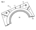
- FIG. 1 A burner insert for an annular combustion chamber is shown schematically in FIG. 1 shown.
- the figure shows a burner insert for an annular combustion chamber in a cut perspective view on its cold side 103.
- an opening 105 In the center of the cold side 103 of the burner insert 100 is an opening 105 into which the burner can be used.
- the burner insert is fastened by means of an annular ridge 107 in a cold side projecting portion 109 of the burner insert 100 to a support structure in the gas turbine housing.
- the cold side 103 of the burner insert 100 is provided with ribs 111.
- support screws 113 are present, which in FIG. 1 are indicated only schematically.
- the screws 113 and the ribs 111 represent support sections, with which the cold side comes to rest on the support structure in the gas turbine housing.
- it may lead to the formation of a non-uniform gap along the peripheral edge of the burner insert, which can lead to an oversupply of cooling air in places with increased gap.
- this is due to the fact that in addition to the ribs 111 and the support bolts 113 are present, a static overdetermination, since the burner insert 100 is to rest on the screws except at the same time on the ribs 11.
- the first object is achieved by a burner insert according to claim 1, the second object by a gas turbine combustor according to claim 5 or a gas turbine according to claim 9.
- the dependent claims contain advantageous embodiments of the invention.
- An inventive burner insert for a gas turbine combustor has a burner insert wall with a cold side and a hot side.
- a burner opening for inserting a burner is formed in the burner insert wall.
- the burner insert has an outer edge delimiting the burner insert wall with an at least partially encircling edge web projecting over the cold side.
- the edge may in this case be substantially circular, for example in the case of a tube combustion chamber, or, for example in the case of an annular combustion chamber, have the shape of the edge of a circular ring cutout. Other contours are basically possible depending on the shape of the combustion chamber.
- the edge web of the burner insert according to the invention leads to an increase in the natural frequencies in comparison to a burner insert according to the prior art, as with reference to FIG. 1 has been described.
- the vibration load of the burner insert during operation of the combustion chamber is therefore reduced in comparison to the burner insert from the prior art.
- the edge web can rest completely on the support structure in the gas turbine housing, so that a uniform gap, preferably a zero gap, is present along the entire edge.
- the edge web is provided with openings for the passage of cooling fluid. To realize the openings, the edge web has pinnacles, between which the openings are formed
- the edge web runs around the entire edge of the burner insert.
- the rigidity of the edge of the burner insert is then particularly high.
- the burner opening is surrounded by an annular, over the cold side projecting and provided with an annular web wall portion. Otherwise, the burner insert wall is formed flat, d. H.
- the existing in the art ribs there are no other structures, such as the existing in the art ribs. In the case of the burner insert according to the invention such ribs are superfluous, since it has been shown that a uniform distribution of the cooling air takes place even without such ribs. Also, a stiffening function of the ribs is not needed in the burner insert according to the invention.
- the burner insert according to the invention makes it possible to save cooling air, since no uneven gap dimensions occur, which can lead to an oversupply in the cooling air supply.
- the reduced supply of cooling air into the combustion chamber results in a reduced pollutant emissions of the gas turbine and higher turbine inlet temperatures, which in turn allows an increase in efficiency of the gas turbine.
- the design of the burner insert according to the invention also enables a cost reduction, since the stiffening screws are eliminated and therefore fewer components are required in comparison to the burner insert described in the introduction.
- a gas turbine combustor according to the invention has at least one burner, at least one combustion chamber wall surrounding a combustion chamber interior, and at least one burner end wall on the burner side. It comprises a burner insert according to the invention whose burner insert wall forms the combustion chamber end wall, the hot side of the burner insert wall facing the combustion chamber interior.
- the combustion chamber wall may be cylindrical in the case of a tube combustion chamber. In the case of an annular combustion chamber, however, two combustion chamber walls are present, namely a radially outer and a radially inner combustion chamber wall.
- a gap may be present between the combustion chamber closure wall formed by the at least one burner insert and the at least one combustion chamber wall, which allows the outflow of cooling air from the cold side of the combustion insert into the combustion chamber.
- the burner-side combustion chamber end wall can be formed in particular by a number in the circumferential direction of the combustion chamber juxtaposed burner inserts. There may be gaps between adjacent burner inserts which allow the flow of cooling air between the burner inserts into the annular combustion chamber.
- a gas turbine according to the invention is equipped with at least one gas turbine combustion chamber, which is designed as a gas turbine combustion chamber according to the invention.
- the gas turbine according to the invention comprises a cooling fluid reservoir, for example a combustion chamber plenum communicating with the output of a compressor, wherein the cold side of the burner insert wall is fluidically connected to the cooling fluid reservoir.
- FIG. 2 shows a gas turbine 1 in a longitudinal section.
- This comprises a compressor section 3, a combustion chamber section 5 and a turbine section 7.
- a shaft 9 extends through all sections of the gas turbine 1.
- the shaft 9 is provided with rings of compressor blades 11 and in the turbine section 7 with rings of turbine blades 13.
- Wreaths of compressor guide vanes 15 are located between the rotor blade rings in the compressor section 3 and rings of turbine guide vanes 17 in the turbine section 17.
- the guide vanes extend from the housing 19 of the gas turbine installation 1 essentially in the radial direction to the shaft 9.
- air 23 is sucked in through an air inlet 21 of the compressor section 3 and compressed by the compressor rotor blades 11.
- the compressed air is supplied to a combustion chamber 25 arranged in the combustion chamber 25, which is configured in the present embodiment as an annular combustion chamber, into which a gaseous or liquid fuel via at least one burner 27 is injected.
- the resulting air-fuel mixture is ignited and burned in the combustion chamber 25.
- the hot combustion exhaust gases flow from the combustor 25 into the turbine section 7, where they expand and cool, imparting momentum to the turbine blades 13.
- the turbine guide vanes 17 serve as nozzles for optimizing the momentum transfer to the rotor blades 13.
- the rotation of the shaft 9 brought about by the momentum transfer is used to drive a load, for example an electric generator.
- the expanded and cooled combustion gases are finally discharged from the gas turbine 1 through an outlet 31.
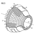
- the annular combustion chamber 25 of in FIG. 2 shown gas turbine is in FIG. 3 shown in a perspective, partially cutaway view.
- Both the outer combustion chamber wall 33 and the inner combustion chamber wall 35 are provided with a hot gas-resistant lining, which is formed from heat shield elements 37.
- heat shield elements in the present embodiment ceramic heat shield elements are used.
- the turbine section 7 facing the end of the combustion chamber has a hot gas outlet opening 39, through which the resulting inside the combustion chamber 25 hot combustion gases can flow to the turbine.
- At the hot gas outlet 39 opposite end of the annular combustion chamber 25 is formed from burner inserts 41 Brennschschschschillerwand available. In each burner insert 41, a burner 27 is received.
- the burner inserts 41 are in this case not directly connected to the outer combustion chamber wall 33 and the inner combustion chamber wall 35, but arranged on a support structure (not shown), which in turn is attached to the housing of the gas turbine. Between the individual burner inserts 41 on the one hand and the outer wall 33 and the inner wall 35 on the other hand remains a gap which allows the inflow of cooling air along the respective wall into the interior of the combustion chamber.
- the burner inserts 41 are arranged so that between them, ie between circumferentially adjacent edges of the burner inserts 41, remain gaps that allow the entry of cooling air into the combustion chamber interior.
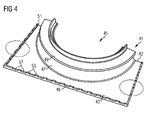
- a burner insert is in FIG. 4 shown in a partially cut perspective view. It comprises a burner insert wall 42 with a cold side 43 and a hot side 44, which is to be turned to the combustion chamber interior (the hot side is in FIG. 4 not recognizable).
- the cold side 43 communicates with the outlet of the compressor in fluid communication, so that compressor air can be bypassed for cooling purposes on the cold side 43 to the temperature of the hot side on a for the material of the burner insert 41 acceptable level.
- the hot side is also provided with a heat-insulating coating, for example in the form of a ceramic coating, in order to reduce the need for cooling air.
- the burner insert 41 has an opening 45 into which the outlet of a burner 27 can be inserted.
- the opening 45 is delimited by a section 47 of the burner insert wall 42 projecting beyond the cold side 43. From this projecting portion 47 extending in the radial direction of the opening 45 extending annular ridge, with which the burner insert 41 can be attached to a support structure.
- the entire outer edge 46 of the burner insert 41 is provided with an over the cold side 43 projecting edge web 51, which gives the edge 46 increased rigidity and ensures that the natural frequency of the burner insert wall 42 is increased.
- Detail views of the edge 46 with the edge web 51 are in the FIGS. 5 and 6 shown.
- the edge web 51 has battlements 53, which are formed by portions of the edge web 51, which project further beyond the cold side 43 than the remaining portions 54 of the edge web 51. If the burner insert is attached to a support structure and forms part of a combustion chamber end wall, lie Pinnacles 53 with the most distant from the cold side 43 end faces 55 on a contact surface of the support structure with a zero gap. Between the pinnacles 53 windows 57 are then formed, can flow through the cooling air, which is usually supplied in the region of the projecting wall portion 47 from the compressor into the combustion chamber. The cooling air can then flow along the cold side 43, which is completely flat except for the edge web 51 and the protruding wall region 47, for cooling.
- the windows 57 between the pinnacles 53 represent openings for the flowing cooling air with a defined passage cross-section, since the end faces 55 of the pinnacles 53 abut with zero gap on the investment structure.
- edge bar 51 in the FIGS. 4 to 6 In the embodiment shown, with crenellations 53 provided to define window openings 57 for the cooling air, in one example, which does not fall under the scope of the invention, it is also possible to project the edge web 51 uniformly over the cold side 43. Cooling air passages can then be realized by means of through-holes 59, for example in the form of bores. A corresponding embodiment of a burner insert is in FIG. 7 shown.
- the edge web extends along the entire outer edge 46 of the burner insert 41
- embodiments are conceivable in which areas of the outer edge 46 of the burner insert 41 have no edge web 51.
- embodiments for cylindrical combustion chambers are possible.
- the outer edge of the burner insert would be substantially circular and the edge web would be present at least along a part of the circumference, preferably around the entire circumference.
- the invention makes it possible to increase the natural frequency of the burner insert and at the same time the targeted adjustment of the outflow of cooling air into the combustion chamber, so that the cooling air can flow only through the predefined column. Associated with this, there are further advantages of the invention such as a longer service life of the burner insert and - by the cooling air saved at the burner insert - a reduction of pollutants at the same power of the burner inserts provided with the gas turbine, when the saved cooling air is supplied to the burner. Alternatively, higher outputs can be achieved with the same emissions.
Landscapes
- Engineering & Computer Science (AREA)
- Chemical & Material Sciences (AREA)
- Combustion & Propulsion (AREA)
- Mechanical Engineering (AREA)
- General Engineering & Computer Science (AREA)
- Turbine Rotor Nozzle Sealing (AREA)
- Gas Burners (AREA)
- Pre-Mixing And Non-Premixing Gas Burner (AREA)
Claims (9)
- Pièce (41) d'insertion d'un brûleur pour une chambre de combustion (25) d'une turbine à gaz, pièce d'insertion qui a une paroi (42) ayant un côté (43) froid et un côté (44) chaud, une ouverture (45) pour un brûleur pour l'insertion d'un brûleur (27) dans la paroi (42) de la pièce d'insertion d'un brûleur étant formée, la pièce d'insertion d'un brûleur ayant un bord (46) délimitant la paroi (4) 2 de la pièce d'insertion d'un brûleur, bord qui a une réglette (51) de bord faisant le tour au moins en partie et en saillie du côté (43) froid et des ouvertures (57) de passage de fluide de refroidissement, caractérisée en ce que la réglette (51) de bord a des dents (53) et les ouvertures (57) sont formées entre les dents (53).
- Pièce (41) d'insertion d'un brûleur suivant la revendication 1,
caractérisée en ce que
les dents sont formées par des parties de la réglette de bord qui dépassent du côté (43) froid plus que les autres parties (54) de la réglette de bord. - Pièce (41) d'insertion d'un brûleur suivant l'une des revendications précédentes,
caractérisée en ce que la réglette (41) de bord fait le tour de tout le bord (46). - Pièce (41) d'insertion d'un brûleur suivant l'une des revendications précédentes,
caractérisée en ce que
l'ouverture (45) pour un brûleur est entourée d'une zone (47) de paroi annulaire en saillie du côté (43) froid et pourvue d'un rebord (49) annulaire et la paroi (42) de la pièce d'insertion d'un brûleur est sinon plate. - Chambre de combustion (25) d'une turbine à gaz ayant au moins un brûleur (27), au moins une paroi (33, 35) de chambre de combustion entourant l'intérieur de la chambre de combustion et une paroi de fermeture de la chambre de combustion du côté du brûleur,
caractérisée en ce que
il y a au moins une pièce (41) d'insertion d'un brûleur suivant l'une des revendications précédentes, dont la paroi (42) forme au moins en partie la paroi de fermeture de la chambre de combustion, le côté (44) chaud de la paroi (42) de la pièce d'insertion d'un brûleur étant tourné vers l'intérieur de la chambre de combustion. - Chambre de combustion (25) d'une turbine à gaz suivant la revendication 5,
caractérisée en ce que
il y a un intervalle entre la paroi de fermeture de la chambre de combustion formée par la au moins une pièce (41) d'insertion d'un brûleur et la au moins une paroi (33, 35) de la chambre de combustion. - Chambre de combustion (25) d'une turbine à gaz suivant l'une des revendications 5 ou 6,
caractérisée en ce que
elle est constituée sous la forme d'une chambre de combustion annulaire ayant un espace intérieur de chambre de combustion annulaire formé entre une paroi (35) intérieure de la chambre de combustion et une paroi (33) extérieure de la chambre de combustion et la paroi de fermeture de la chambre de combustion du côté du brûleur est formée par un certain nombre de pièces (41) d'insertion d'un brûleur, disposées les unes à côtés des autres dans la direction périphérique de la chambre de combustion (25) annulaire. - Chambre de combustion (25) d'une turbine à gaz suivant la revendication 7,
caractérisée en ce que
il y a des intervalles entre deux pièces (41) d'insertion voisines d'un brûleur. - Turbine (1) à gaz ayant au moins une chambre de combustion (25) de turbine à gaz,
caractérisée en ce que- la au moins une chambre de combustion (25) d'une turbine à gaz est une chambre de combustion d'une turbine à gaz suivant l'une des revendications 5 à 8,- il y a un réservoir de fluide de refroidissement et- le côté (43) froid de la paroi (42) de la pièce d'insertion d'un brûleur est en liaison fluidique avec le réservoir de fluide de refroidissement.
Priority Applications (1)
| Application Number | Priority Date | Filing Date | Title |
|---|---|---|---|
| EP09823099.8A EP2340397B1 (fr) | 2008-10-29 | 2009-09-14 | Pièce du brûleur pour une chambre de combustion d'une turbine à gaz et turbine à gaz |
Applications Claiming Priority (3)
| Application Number | Priority Date | Filing Date | Title |
|---|---|---|---|
| EP08018907A EP2182285A1 (fr) | 2008-10-29 | 2008-10-29 | Pièce du brûleur pour une chambre de combustion d'une turbine à gaz et turbine à gaz |
| PCT/EP2009/061854 WO2010049206A1 (fr) | 2008-10-29 | 2009-09-14 | Insert de brûleur pour une chambre de combustion d'une turbine à gaz et turbine à gaz |
| EP09823099.8A EP2340397B1 (fr) | 2008-10-29 | 2009-09-14 | Pièce du brûleur pour une chambre de combustion d'une turbine à gaz et turbine à gaz |
Publications (2)
| Publication Number | Publication Date |
|---|---|
| EP2340397A1 EP2340397A1 (fr) | 2011-07-06 |
| EP2340397B1 true EP2340397B1 (fr) | 2013-07-31 |
Family
ID=40672584
Family Applications (2)
| Application Number | Title | Priority Date | Filing Date |
|---|---|---|---|
| EP08018907A Withdrawn EP2182285A1 (fr) | 2008-10-29 | 2008-10-29 | Pièce du brûleur pour une chambre de combustion d'une turbine à gaz et turbine à gaz |
| EP09823099.8A Active EP2340397B1 (fr) | 2008-10-29 | 2009-09-14 | Pièce du brûleur pour une chambre de combustion d'une turbine à gaz et turbine à gaz |
Family Applications Before (1)
| Application Number | Title | Priority Date | Filing Date |
|---|---|---|---|
| EP08018907A Withdrawn EP2182285A1 (fr) | 2008-10-29 | 2008-10-29 | Pièce du brûleur pour une chambre de combustion d'une turbine à gaz et turbine à gaz |
Country Status (7)
| Country | Link |
|---|---|
| US (1) | US9074771B2 (fr) |
| EP (2) | EP2182285A1 (fr) |
| JP (1) | JP5349605B2 (fr) |
| CN (1) | CN102203509B (fr) |
| ES (1) | ES2426395T3 (fr) |
| RU (1) | RU2530684C2 (fr) |
| WO (1) | WO2010049206A1 (fr) |
Families Citing this family (15)
| Publication number | Priority date | Publication date | Assignee | Title |
|---|---|---|---|---|
| DE102012204103A1 (de) * | 2012-03-15 | 2013-09-19 | Siemens Aktiengesellschaft | Hitzeschildelement für einen Verdichterluftbypass um die Brennkammer |
| US9322560B2 (en) * | 2012-09-28 | 2016-04-26 | United Technologies Corporation | Combustor bulkhead assembly |
| US20150033746A1 (en) * | 2013-08-02 | 2015-02-05 | Solar Turbines Incorporated | Heat shield with standoffs |
| US9534786B2 (en) * | 2014-08-08 | 2017-01-03 | Pratt & Whitney Canada Corp. | Combustor heat shield |
| US10267521B2 (en) | 2015-04-13 | 2019-04-23 | Pratt & Whitney Canada Corp. | Combustor heat shield |
| DE102016206188A1 (de) * | 2016-04-13 | 2017-10-19 | Rolls-Royce Deutschland Ltd & Co Kg | Brennkammerschindel einer Gasturbine |
| DE102016224632A1 (de) * | 2016-12-09 | 2018-06-14 | Rolls-Royce Deutschland Ltd & Co Kg | Plattenförmiges Bauteil einer Gasturbine sowie Verfahren zu dessen Herstellung |
| US10830435B2 (en) | 2018-02-06 | 2020-11-10 | Raytheon Technologies Corporation | Diffusing hole for rail effusion |
| US11009230B2 (en) | 2018-02-06 | 2021-05-18 | Raytheon Technologies Corporation | Undercut combustor panel rail |
| US11248791B2 (en) | 2018-02-06 | 2022-02-15 | Raytheon Technologies Corporation | Pull-plane effusion combustor panel |
| US11022307B2 (en) | 2018-02-22 | 2021-06-01 | Raytheon Technology Corporation | Gas turbine combustor heat shield panel having multi-direction hole for rail effusion cooling |
| US20190285276A1 (en) * | 2018-03-14 | 2019-09-19 | United Technologies Corporation | Castellated combustor panels |
| DE102018212394B4 (de) * | 2018-07-25 | 2024-03-28 | Rolls-Royce Deutschland Ltd & Co Kg | Brennkammerbaugruppe mit Strömungsleiteinrichtung aufweisendem Wandelement |
| US11015807B2 (en) * | 2019-01-30 | 2021-05-25 | Pratt & Whitney Canada Corp. | Combustor heat shield cooling |
| EP3964753A1 (fr) * | 2020-09-07 | 2022-03-09 | Siemens Energy Global GmbH & Co. KG | Joint d'étanchéité destiné à l'utilisation dans un élément pare-chaleur |
Family Cites Families (18)
| Publication number | Priority date | Publication date | Assignee | Title |
|---|---|---|---|---|
| GB2107448B (en) * | 1980-10-21 | 1984-06-06 | Rolls Royce | Gas turbine engine combustion chambers |
| US4914918A (en) * | 1988-09-26 | 1990-04-10 | United Technologies Corporation | Combustor segmented deflector |
| GB9018014D0 (en) * | 1990-08-16 | 1990-10-03 | Rolls Royce Plc | Gas turbine engine combustor |
| GB2287310B (en) * | 1994-03-01 | 1997-12-03 | Rolls Royce Plc | Gas turbine engine combustor heatshield |
| US5419115A (en) * | 1994-04-29 | 1995-05-30 | United Technologies Corporation | Bulkhead and fuel nozzle guide assembly for an annular combustion chamber |
| DE4427222A1 (de) * | 1994-08-01 | 1996-02-08 | Bmw Rolls Royce Gmbh | Hitzeschild für eine Gasturbinen-Brennkammer |
| US6032457A (en) * | 1996-06-27 | 2000-03-07 | United Technologies Corporation | Fuel nozzle guide |
| US5974805A (en) * | 1997-10-28 | 1999-11-02 | Rolls-Royce Plc | Heat shielding for a turbine combustor |
| US6164074A (en) * | 1997-12-12 | 2000-12-26 | United Technologies Corporation | Combustor bulkhead with improved cooling and air recirculation zone |
| US6751961B2 (en) * | 2002-05-14 | 2004-06-22 | United Technologies Corporation | Bulkhead panel for use in a combustion chamber of a gas turbine engine |
| US6792757B2 (en) * | 2002-11-05 | 2004-09-21 | Honeywell International Inc. | Gas turbine combustor heat shield impingement cooling baffle |
| RU31818U1 (ru) * | 2002-11-21 | 2003-08-27 | ОАО Самарский научно-технический комплекс им. Н.Д. Кузнецова | Газотурбинный двигатель НК-37, компрессор, камера сгорания, турбина |
| US7080515B2 (en) | 2002-12-23 | 2006-07-25 | Siemens Westinghouse Power Corporation | Gas turbine can annular combustor |
| DE502004011695D1 (de) | 2004-01-21 | 2010-11-11 | Siemens Ag | Brenner mit gekühltem Bauteil, Gasturbine sowie Verfahren zur Kühlung des Bauteils |
| RU52982U1 (ru) * | 2005-08-03 | 2006-04-27 | ЭКОЛ спол. с.р.о. | Горелка для сжигания с низкими эмиссиями вредных веществ и система горелок |
| EP1767855A1 (fr) | 2005-09-27 | 2007-03-28 | Siemens Aktiengesellschaft | Chambre de combustion et turbine à gaz |
| RU52992U1 (ru) | 2005-10-24 | 2006-04-27 | Ираклий Отарович Чиквиладзе | Радиатор двигателя внутреннего сгорания гоночного автомобиля |
| US7665306B2 (en) * | 2007-06-22 | 2010-02-23 | Honeywell International Inc. | Heat shields for use in combustors |
-
2008
- 2008-10-29 EP EP08018907A patent/EP2182285A1/fr not_active Withdrawn
-
2009
- 2009-09-14 WO PCT/EP2009/061854 patent/WO2010049206A1/fr not_active Ceased
- 2009-09-14 ES ES09823099T patent/ES2426395T3/es active Active
- 2009-09-14 CN CN200980142861.0A patent/CN102203509B/zh active Active
- 2009-09-14 EP EP09823099.8A patent/EP2340397B1/fr active Active
- 2009-09-14 RU RU2011121647/06A patent/RU2530684C2/ru active
- 2009-09-14 JP JP2011533647A patent/JP5349605B2/ja not_active Expired - Fee Related
- 2009-09-14 US US13/126,239 patent/US9074771B2/en not_active Expired - Fee Related
Also Published As
| Publication number | Publication date |
|---|---|
| US20110197590A1 (en) | 2011-08-18 |
| EP2182285A1 (fr) | 2010-05-05 |
| WO2010049206A1 (fr) | 2010-05-06 |
| JP2012506991A (ja) | 2012-03-22 |
| RU2530684C2 (ru) | 2014-10-10 |
| JP5349605B2 (ja) | 2013-11-20 |
| CN102203509A (zh) | 2011-09-28 |
| EP2340397A1 (fr) | 2011-07-06 |
| US9074771B2 (en) | 2015-07-07 |
| RU2011121647A (ru) | 2012-12-10 |
| ES2426395T3 (es) | 2013-10-23 |
| CN102203509B (zh) | 2014-07-09 |
Similar Documents
| Publication | Publication Date | Title |
|---|---|---|
| EP2340397B1 (fr) | Pièce du brûleur pour une chambre de combustion d'une turbine à gaz et turbine à gaz | |
| DE60105531T2 (de) | Gasturbinenbrennkammer, Gasturbine und Düsentriebwerk | |
| DE102005025823B4 (de) | Verfahren und Vorrichtung zum Kühlen einer Brennkammerauskleidung und eines Übergangsteils einer Gasturbine | |
| EP0244693B1 (fr) | Dispositif protecteur contre le surchauffage à gaz chaud pour les propulseurs à turbine à gaz | |
| DE102008022669A1 (de) | Brennstoffdüse und Verfahren für deren Herstellung | |
| EP2808611B1 (fr) | Injecteur pour l'introduction d'un mélange air-carburant dans une chambre de combustion | |
| DE102014103005B4 (de) | Verfahren und Vorrichtung zur Verbesserung der Wärmeübertragung in Turbinenabschnitten von Gasturbinen | |
| DE102015112767A1 (de) | Brennstoffinjektoranordnungen in Verbrennungsturbinen | |
| DE112019000871B4 (de) | Brennkammer und damit ausgestattete gasturbine | |
| CH701454B1 (de) | Brenner mit einem Strömungskonditionierer. | |
| EP3132202B1 (fr) | Element de bouclier thermique avec contournement | |
| DE102015113146A1 (de) | Systeme und Vorrichtungen im Zusammenhang mit Gasturbinenbrennkammern | |
| DE102011055109A1 (de) | Anlage zum Lenken des Luftstroms in einer Kraftstoffdüsenanordnung | |
| DE102022210198B4 (de) | Übergangsstück, Brennkammer und Gasturbinentriebwerk | |
| EP2507557B1 (fr) | Agencement de brûleur | |
| DE60225411T2 (de) | Flammrohr oder Bekleidung für die Brennkammer einer Gasturbine mit niedriger Schadstoffemission | |
| EP2187125A1 (fr) | Dispositif et procédé destinés à l'amortissement d'oscillations de combustion | |
| EP3245451B1 (fr) | Chambre de combustion pour turbine à gaz, délimitée par une paroi | |
| EP1904717B1 (fr) | Element de carter conducteur de gaz chaud, enveloppe de protection d'arbre et systeme de turbine a gaz | |
| EP2236932A1 (fr) | Procédé de fonctionnement d'un brûleur et brûleur, notamment pour une turbine à gaz | |
| DE102019104814B4 (de) | Mit einem Einsatzträger ausgestattete Turbinenschaufel | |
| EP2409086B1 (fr) | Arrangement de brûleur pour une turbine à gaz | |
| EP1724526A1 (fr) | Coquille de turbine à gaz, turbine à gaz et procédé de démarrage et d'arrêt d'une turbine à gaz | |
| DE102019219697B4 (de) | Gasturbinenbrennkammer und gasturbine | |
| EP3004741B1 (fr) | Chambre de combustion tubulaire dotée d'une zone d'extrémité et turbine à gaz |
Legal Events
| Date | Code | Title | Description |
|---|---|---|---|
| PUAI | Public reference made under article 153(3) epc to a published international application that has entered the european phase |
Free format text: ORIGINAL CODE: 0009012 |
|
| 17P | Request for examination filed |
Effective date: 20110323 |
|
| AK | Designated contracting states |
Kind code of ref document: A1 Designated state(s): AT BE BG CH CY CZ DE DK EE ES FI FR GB GR HR HU IE IS IT LI LT LU LV MC MK MT NL NO PL PT RO SE SI SK SM TR |
|
| AX | Request for extension of the european patent |
Extension state: AL BA RS |
|
| DAX | Request for extension of the european patent (deleted) | ||
| GRAP | Despatch of communication of intention to grant a patent |
Free format text: ORIGINAL CODE: EPIDOSNIGR1 |
|
| RAP1 | Party data changed (applicant data changed or rights of an application transferred) |
Owner name: SIEMENS AKTIENGESELLSCHAFT |
|
| GRAS | Grant fee paid |
Free format text: ORIGINAL CODE: EPIDOSNIGR3 |
|
| GRAA | (expected) grant |
Free format text: ORIGINAL CODE: 0009210 |
|
| AK | Designated contracting states |
Kind code of ref document: B1 Designated state(s): AT BE BG CH CY CZ DE DK EE ES FI FR GB GR HR HU IE IS IT LI LT LU LV MC MK MT NL NO PL PT RO SE SI SK SM TR |
|
| REG | Reference to a national code |
Ref country code: GB Ref legal event code: FG4D Free format text: NOT ENGLISH Ref country code: CH Ref legal event code: EP |
|
| REG | Reference to a national code |
Ref country code: AT Ref legal event code: REF Ref document number: 624881 Country of ref document: AT Kind code of ref document: T Effective date: 20130815 Ref country code: CH Ref legal event code: NV Representative=s name: SIEMENS SCHWEIZ AG, CH |
|
| REG | Reference to a national code |
Ref country code: IE Ref legal event code: FG4D Free format text: LANGUAGE OF EP DOCUMENT: GERMAN |
|
| REG | Reference to a national code |
Ref country code: DE Ref legal event code: R096 Ref document number: 502009007699 Country of ref document: DE Effective date: 20130926 |
|
| REG | Reference to a national code |
Ref country code: ES Ref legal event code: FG2A Ref document number: 2426395 Country of ref document: ES Kind code of ref document: T3 Effective date: 20131023 |
|
| REG | Reference to a national code |
Ref country code: NL Ref legal event code: VDEP Effective date: 20130731 |
|
| REG | Reference to a national code |
Ref country code: LT Ref legal event code: MG4D |
|
| PG25 | Lapsed in a contracting state [announced via postgrant information from national office to epo] |
Ref country code: CY Free format text: LAPSE BECAUSE OF FAILURE TO SUBMIT A TRANSLATION OF THE DESCRIPTION OR TO PAY THE FEE WITHIN THE PRESCRIBED TIME-LIMIT Effective date: 20130724 Ref country code: NO Free format text: LAPSE BECAUSE OF FAILURE TO SUBMIT A TRANSLATION OF THE DESCRIPTION OR TO PAY THE FEE WITHIN THE PRESCRIBED TIME-LIMIT Effective date: 20131031 Ref country code: SE Free format text: LAPSE BECAUSE OF FAILURE TO SUBMIT A TRANSLATION OF THE DESCRIPTION OR TO PAY THE FEE WITHIN THE PRESCRIBED TIME-LIMIT Effective date: 20130731 Ref country code: LT Free format text: LAPSE BECAUSE OF FAILURE TO SUBMIT A TRANSLATION OF THE DESCRIPTION OR TO PAY THE FEE WITHIN THE PRESCRIBED TIME-LIMIT Effective date: 20130731 Ref country code: HR Free format text: LAPSE BECAUSE OF FAILURE TO SUBMIT A TRANSLATION OF THE DESCRIPTION OR TO PAY THE FEE WITHIN THE PRESCRIBED TIME-LIMIT Effective date: 20130731 Ref country code: PT Free format text: LAPSE BECAUSE OF FAILURE TO SUBMIT A TRANSLATION OF THE DESCRIPTION OR TO PAY THE FEE WITHIN THE PRESCRIBED TIME-LIMIT Effective date: 20131202 Ref country code: IS Free format text: LAPSE BECAUSE OF FAILURE TO SUBMIT A TRANSLATION OF THE DESCRIPTION OR TO PAY THE FEE WITHIN THE PRESCRIBED TIME-LIMIT Effective date: 20131130 |
|
| PG25 | Lapsed in a contracting state [announced via postgrant information from national office to epo] |
Ref country code: GR Free format text: LAPSE BECAUSE OF FAILURE TO SUBMIT A TRANSLATION OF THE DESCRIPTION OR TO PAY THE FEE WITHIN THE PRESCRIBED TIME-LIMIT Effective date: 20131101 Ref country code: SI Free format text: LAPSE BECAUSE OF FAILURE TO SUBMIT A TRANSLATION OF THE DESCRIPTION OR TO PAY THE FEE WITHIN THE PRESCRIBED TIME-LIMIT Effective date: 20130731 Ref country code: LV Free format text: LAPSE BECAUSE OF FAILURE TO SUBMIT A TRANSLATION OF THE DESCRIPTION OR TO PAY THE FEE WITHIN THE PRESCRIBED TIME-LIMIT Effective date: 20130731 Ref country code: FI Free format text: LAPSE BECAUSE OF FAILURE TO SUBMIT A TRANSLATION OF THE DESCRIPTION OR TO PAY THE FEE WITHIN THE PRESCRIBED TIME-LIMIT Effective date: 20130731 Ref country code: PL Free format text: LAPSE BECAUSE OF FAILURE TO SUBMIT A TRANSLATION OF THE DESCRIPTION OR TO PAY THE FEE WITHIN THE PRESCRIBED TIME-LIMIT Effective date: 20130731 Ref country code: NL Free format text: LAPSE BECAUSE OF FAILURE TO SUBMIT A TRANSLATION OF THE DESCRIPTION OR TO PAY THE FEE WITHIN THE PRESCRIBED TIME-LIMIT Effective date: 20130731 |
|
| BERE | Be: lapsed |
Owner name: SIEMENS A.G. Effective date: 20130930 |
|
| PG25 | Lapsed in a contracting state [announced via postgrant information from national office to epo] |
Ref country code: CY Free format text: LAPSE BECAUSE OF FAILURE TO SUBMIT A TRANSLATION OF THE DESCRIPTION OR TO PAY THE FEE WITHIN THE PRESCRIBED TIME-LIMIT Effective date: 20130731 |
|
| PG25 | Lapsed in a contracting state [announced via postgrant information from national office to epo] |
Ref country code: DK Free format text: LAPSE BECAUSE OF FAILURE TO SUBMIT A TRANSLATION OF THE DESCRIPTION OR TO PAY THE FEE WITHIN THE PRESCRIBED TIME-LIMIT Effective date: 20130731 Ref country code: RO Free format text: LAPSE BECAUSE OF FAILURE TO SUBMIT A TRANSLATION OF THE DESCRIPTION OR TO PAY THE FEE WITHIN THE PRESCRIBED TIME-LIMIT Effective date: 20130731 Ref country code: CZ Free format text: LAPSE BECAUSE OF FAILURE TO SUBMIT A TRANSLATION OF THE DESCRIPTION OR TO PAY THE FEE WITHIN THE PRESCRIBED TIME-LIMIT Effective date: 20130731 Ref country code: MC Free format text: LAPSE BECAUSE OF FAILURE TO SUBMIT A TRANSLATION OF THE DESCRIPTION OR TO PAY THE FEE WITHIN THE PRESCRIBED TIME-LIMIT Effective date: 20130731 Ref country code: EE Free format text: LAPSE BECAUSE OF FAILURE TO SUBMIT A TRANSLATION OF THE DESCRIPTION OR TO PAY THE FEE WITHIN THE PRESCRIBED TIME-LIMIT Effective date: 20130731 Ref country code: SK Free format text: LAPSE BECAUSE OF FAILURE TO SUBMIT A TRANSLATION OF THE DESCRIPTION OR TO PAY THE FEE WITHIN THE PRESCRIBED TIME-LIMIT Effective date: 20130731 |
|
| PLBE | No opposition filed within time limit |
Free format text: ORIGINAL CODE: 0009261 |
|
| STAA | Information on the status of an ep patent application or granted ep patent |
Free format text: STATUS: NO OPPOSITION FILED WITHIN TIME LIMIT |
|
| REG | Reference to a national code |
Ref country code: FR Ref legal event code: ST Effective date: 20140530 |
|
| REG | Reference to a national code |
Ref country code: IE Ref legal event code: MM4A |
|
| 26N | No opposition filed |
Effective date: 20140502 |
|
| PG25 | Lapsed in a contracting state [announced via postgrant information from national office to epo] |
Ref country code: IE Free format text: LAPSE BECAUSE OF NON-PAYMENT OF DUE FEES Effective date: 20130914 Ref country code: BE Free format text: LAPSE BECAUSE OF NON-PAYMENT OF DUE FEES Effective date: 20130930 |
|
| REG | Reference to a national code |
Ref country code: DE Ref legal event code: R097 Ref document number: 502009007699 Country of ref document: DE Effective date: 20140502 |
|
| PG25 | Lapsed in a contracting state [announced via postgrant information from national office to epo] |
Ref country code: FR Free format text: LAPSE BECAUSE OF NON-PAYMENT OF DUE FEES Effective date: 20130930 |
|
| PG25 | Lapsed in a contracting state [announced via postgrant information from national office to epo] |
Ref country code: SM Free format text: LAPSE BECAUSE OF FAILURE TO SUBMIT A TRANSLATION OF THE DESCRIPTION OR TO PAY THE FEE WITHIN THE PRESCRIBED TIME-LIMIT Effective date: 20130731 |
|
| PG25 | Lapsed in a contracting state [announced via postgrant information from national office to epo] |
Ref country code: MT Free format text: LAPSE BECAUSE OF FAILURE TO SUBMIT A TRANSLATION OF THE DESCRIPTION OR TO PAY THE FEE WITHIN THE PRESCRIBED TIME-LIMIT Effective date: 20130731 Ref country code: TR Free format text: LAPSE BECAUSE OF FAILURE TO SUBMIT A TRANSLATION OF THE DESCRIPTION OR TO PAY THE FEE WITHIN THE PRESCRIBED TIME-LIMIT Effective date: 20130731 |
|
| PG25 | Lapsed in a contracting state [announced via postgrant information from national office to epo] |
Ref country code: MK Free format text: LAPSE BECAUSE OF FAILURE TO SUBMIT A TRANSLATION OF THE DESCRIPTION OR TO PAY THE FEE WITHIN THE PRESCRIBED TIME-LIMIT Effective date: 20130731 Ref country code: BG Free format text: LAPSE BECAUSE OF FAILURE TO SUBMIT A TRANSLATION OF THE DESCRIPTION OR TO PAY THE FEE WITHIN THE PRESCRIBED TIME-LIMIT Effective date: 20130731 Ref country code: LU Free format text: LAPSE BECAUSE OF NON-PAYMENT OF DUE FEES Effective date: 20130914 Ref country code: HU Free format text: LAPSE BECAUSE OF FAILURE TO SUBMIT A TRANSLATION OF THE DESCRIPTION OR TO PAY THE FEE WITHIN THE PRESCRIBED TIME-LIMIT; INVALID AB INITIO Effective date: 20090914 |
|
| REG | Reference to a national code |
Ref country code: AT Ref legal event code: MM01 Ref document number: 624881 Country of ref document: AT Kind code of ref document: T Effective date: 20140914 |
|
| PG25 | Lapsed in a contracting state [announced via postgrant information from national office to epo] |
Ref country code: AT Free format text: LAPSE BECAUSE OF NON-PAYMENT OF DUE FEES Effective date: 20140914 |
|
| PGFP | Annual fee paid to national office [announced via postgrant information from national office to epo] |
Ref country code: CH Payment date: 20161202 Year of fee payment: 8 |
|
| REG | Reference to a national code |
Ref country code: CH Ref legal event code: PCOW Free format text: NEW ADDRESS: WERNER-VON-SIEMENS-STRASSE 1, 80333 MUENCHEN (DE) |
|
| REG | Reference to a national code |
Ref country code: CH Ref legal event code: PL |
|
| PG25 | Lapsed in a contracting state [announced via postgrant information from national office to epo] |
Ref country code: CH Free format text: LAPSE BECAUSE OF NON-PAYMENT OF DUE FEES Effective date: 20170930 Ref country code: LI Free format text: LAPSE BECAUSE OF NON-PAYMENT OF DUE FEES Effective date: 20170930 |
|
| PGFP | Annual fee paid to national office [announced via postgrant information from national office to epo] |
Ref country code: ES Payment date: 20181217 Year of fee payment: 10 |
|
| REG | Reference to a national code |
Ref country code: DE Ref legal event code: R081 Ref document number: 502009007699 Country of ref document: DE Owner name: SIEMENS ENERGY GLOBAL GMBH & CO. KG, DE Free format text: FORMER OWNER: SIEMENS AKTIENGESELLSCHAFT, 80333 MUENCHEN, DE |
|
| REG | Reference to a national code |
Ref country code: ES Ref legal event code: FD2A Effective date: 20210128 |
|
| PG25 | Lapsed in a contracting state [announced via postgrant information from national office to epo] |
Ref country code: ES Free format text: LAPSE BECAUSE OF NON-PAYMENT OF DUE FEES Effective date: 20190915 |
|
| REG | Reference to a national code |
Ref country code: GB Ref legal event code: 732E Free format text: REGISTERED BETWEEN 20220818 AND 20220824 |
|
| PGFP | Annual fee paid to national office [announced via postgrant information from national office to epo] |
Ref country code: DE Payment date: 20250926 Year of fee payment: 17 |
|
| PGFP | Annual fee paid to national office [announced via postgrant information from national office to epo] |
Ref country code: IT Payment date: 20250922 Year of fee payment: 17 |
|
| PGFP | Annual fee paid to national office [announced via postgrant information from national office to epo] |
Ref country code: GB Payment date: 20250923 Year of fee payment: 17 |