EP1744202A1 - Progressive Brillenlinse - Google Patents
Progressive Brillenlinse Download PDFInfo
- Publication number
- EP1744202A1 EP1744202A1 EP06290652A EP06290652A EP1744202A1 EP 1744202 A1 EP1744202 A1 EP 1744202A1 EP 06290652 A EP06290652 A EP 06290652A EP 06290652 A EP06290652 A EP 06290652A EP 1744202 A1 EP1744202 A1 EP 1744202A1
- Authority
- EP
- European Patent Office
- Prior art keywords
- lens
- vision
- sphere
- addition
- meridian
- Prior art date
- Legal status (The legal status is an assumption and is not a legal conclusion. Google has not performed a legal analysis and makes no representation as to the accuracy of the status listed.)
- Granted
Links
Images


Classifications
-
- G—PHYSICS
- G02—OPTICS
- G02C—SPECTACLES; SUNGLASSES OR GOGGLES INSOFAR AS THEY HAVE THE SAME FEATURES AS SPECTACLES; CONTACT LENSES
- G02C7/00—Optical parts
- G02C7/02—Lenses; Lens systems ; Methods of designing lenses
- G02C7/06—Lenses; Lens systems ; Methods of designing lenses bifocal; multifocal ; progressive
- G02C7/061—Spectacle lenses with progressively varying focal power
- G02C7/063—Shape of the progressive surface
-
- G—PHYSICS
- G02—OPTICS
- G02C—SPECTACLES; SUNGLASSES OR GOGGLES INSOFAR AS THEY HAVE THE SAME FEATURES AS SPECTACLES; CONTACT LENSES
- G02C7/00—Optical parts
-
- G—PHYSICS
- G02—OPTICS
- G02C—SPECTACLES; SUNGLASSES OR GOGGLES INSOFAR AS THEY HAVE THE SAME FEATURES AS SPECTACLES; CONTACT LENSES
- G02C7/00—Optical parts
- G02C7/02—Lenses; Lens systems ; Methods of designing lenses
- G02C7/04—Contact lenses for the eyes
-
- G—PHYSICS
- G02—OPTICS
- G02C—SPECTACLES; SUNGLASSES OR GOGGLES INSOFAR AS THEY HAVE THE SAME FEATURES AS SPECTACLES; CONTACT LENSES
- G02C7/00—Optical parts
- G02C7/02—Lenses; Lens systems ; Methods of designing lenses
- G02C7/06—Lenses; Lens systems ; Methods of designing lenses bifocal; multifocal ; progressive
- G02C7/061—Spectacle lenses with progressively varying focal power
- G02C7/063—Shape of the progressive surface
- G02C7/065—Properties on the principal line
Definitions
- the present invention relates to an ophthalmic lens.
- Any ophthalmic lens intended to be carried in a frame, is associated with a prescription.
- the ophthalmic prescription may include a positive or negative power prescription and a prescription for astigmatism. These prescriptions correspond to corrections to be made to the wearer of the lenses to correct the defects of his vision.
- a lens is mounted in the frame according to the prescription and the position of the wearer's eyes relative to the frame.
- prescription is reduced to a prescription of power.
- the lens is said to be unifocal and has a symmetry of revolution. It is simply mounted in the frame so that the principal direction of the wearer's gaze coincides with the axis of symmetry of the lens.
- the value of the power correction is different in far vision and in near vision, because of the difficulties of accommodation in near vision.
- the prescription is then composed of a power value in far vision and an addition (or progression of power) representative of the power increment between distant vision and near vision; this amounts to a far-sighted power prescription and a close-vision power prescription.
- Lenses adapted to presbyopic carriers are progressive multifocal lenses; these lenses are described by examples in FR-A-2,699,294 , US-A-5,270,745 or US-A-5,272,495 , FR-A-2,683,642 , FR-A-2,699,294 or FR-A-2,704,327 .
- Progressive multifocal ophthalmic lenses include a far vision zone, a near vision zone, an intermediate vision zone, a main progression meridian crossing these three zones. They are generally determined by optimization, based on a number of constraints imposed on the different characteristics of the lens. These lenses are general, in that they are adapted to the different common needs of the wearer.
- lenses that do not have a far vision zone with a reference point, unlike conventional progressive multifocal lenses; these lenses are described in FR-A-2,588,973 . These lenses are prescribed only according to the power required for carrier in near vision, regardless of the power required by the wearer in far vision.
- the lens provides a central portion that has a spherical power addition providing the wearer with a near perfect vision. It also has a slight decrease in power in the upper part, which provides the wearer a clear vision also beyond the usual field of near vision.
- the lens has a point at a power value equal to the near-vision power rating, a higher power zone in the lower portion of the lens, and a lower power zone in the upper portion of the lens.
- FR-A-2,769,997 proposes a lens having, compared with a conventional progressive multifocal lens, a stabilized and more important near-vision zone, a significant increase in near-vision and intermediate-vision field widths, as well as a reduction in aberrations, and in particular astigmatism. It provides an appropriate correction for distances between 40 and 80 cm and, in most cases, for distances between 40 cm and 2 m.
- This lens is actually a near-vision near-vision lens, emphasizing near-vision while providing clear vision beyond the usual near-vision range. By cons, no vision by far is available.
- This lens is particularly suitable for computer work. It is prescribed to young presbyopes, only according to prescription in near vision. The rear face of the lens is machined to provide near-vision power that is appropriate for the prescription, regardless of distance vision prescription. Just two front faces to cover all the needs of carriers.
- FR-A-2,769,999 proposes a progressive multifocal ophthalmic lens having an improved softness with a monotonous sphere variation as a function of the angle on a 20 mm radius circle centered on the geometric center of the lens on either side of the meridian.
- This lens provides a far-away vision encompassing an angular sector originating from the geometric center of the lens and a center angle greater than 150 °.
- Multifocal lenses may comprise a complex multifocal face (that is to say not admitting an axis of revolution, typically a surface carrying a power progression) , for example the opposite face to the wearer of the glasses, and a spherical or toric surface, called prescription face.
- This spherical or toric surface makes it possible to adapt the lens to the ametropia of the user, so that a multifocal lens is generally defined only by its complex surface.
- Different complex faces are defined for a given product, depending on the addition and the base (or mean sphere in far vision). From semi-finished lenses, of which only the multifocal face is shaped, it is possible to prepare lenses adapted to each wearer by simple machining of a spherical or toric prescription face.
- a wearer can be offered a prescription for astigmatism.
- a prescription is made by the ophthalmologist, in far vision, in the form of a pair formed of an axis value (in degrees) and an amplitude value (in diopters).
- the amplitude value represents the difference 1 / R 1 - 1 / R 2 between the main curvatures;
- the axis value represents the orientation, with respect to a reference axis and in an agreed direction of rotation, of the maximum curvature 1 / R 1 .
- the amplitude value represents the difference between the minimum and maximum powers in a given direction and the axis represents the orientation of the maximum power.
- astigmatism is used to designate the torque (amplitude, angle); Although it is an abuse of language, it is sometimes used to describe the amplitude of astigmatism. The context allows the skilled person to understand what meaning is meant.
- the invention provides a lens to which it is easier to adapt than conventional ophthalmic lenses; it ensures the wearer a great softness for excellent perception in peripheral vision by limiting the cylinder values while ensuring good accessibility to the powers necessary for near vision.
- a lens is particularly adapted to the comfort of hyperopic carriers.
- the invention also relates to visual equipment comprising at least one such lens and a method for correcting the vision of a presbyopic subject, comprising providing to the subject or wearing by the subject of such equipment.
- the complex face of the lens may be the front face (remote from the wearer), as is the case for progressive multifocal lenses of the state of the art. Lenses with a radius of 30 mm are considered.
- the invention proposes a progressive multifocal ophthalmic lens having a great softness for an excellent perception in peripheral vision, with in addition a good accessibility in near vision.
- the lens improves peripheral vision by limiting cylinder variations in the peripheral areas of the meridian.
- the proposed lens also provides good accessibility to the power required for near vision, allowing the wearer to see satisfactorily at distances of about 40 cm without requiring him to lower his eyes a lot, the near-vision zone being accessible. from 14 mm under the mounting cross.
- the lens is thus a lens particularly suitable for hypermetropic wearers who are particularly sensitive to peripheral distortions.
- the lens has a prescription such that the powers prescribed to the wearer in far vision and in near vision are reached on the lens.
- the lens is described hereinafter with reference to four embodiments.
- the lens of the first embodiment shown in FIGS. 1 to 3, is adapted to presbyopic hyperopic carriers having a power progression prescription of 1.5 diopters.
- the lenses of the second and third embodiments shown in FIGS. 4 to 6 and 7 to 9, are adapted to presbyopic hypermetropic carriers having a power progression prescription equal to 2 diopters.
- the lens of the second embodiment ( Figures 4 to 6) holds account of the conditions worn (aspherization showing the construction cylinder) in the surface modeling while the lens of the third embodiment ( Figures 7 to 9) does not take into account.
- the lens of the fourth embodiment shown in FIGS. 10 to 12, is adapted to presbyopic hyperopic carriers having a power progression prescription equal to 2.5 diopters.
- the lens has a substantially umbilical line, called meridian line, on which the cylinder is virtually zero.
- the meridian merges with the vertical axis in the upper part of the lens and has an inclination on the nasal side in the lower part of the lens, the convergence being more marked in near vision.
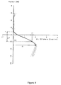
- Figure 1 shows a diagram of the main curvatures and the sphere on the meridian of a lens according to a first embodiment of the invention.
- the points on the complex surface of the lens are marked in FIG. 1 as in FIGS. 2 and 3 with respect to an orthonormal coordinate system originating from the geometric center (0, 0) and whose ordinate axis is vertical and the horizontal x-axis.
- Figure 1 is carried on the abscissa axis the curvature or the sphere in diopters; on the y-axis is the position on the meridian of the lens, in millimeters.
- FIG. 1 shows a diagram of the main curvatures and the sphere on the meridian of a lens according to a first embodiment of the invention.
- the points on the complex surface of the lens are marked in FIG. 1 as in FIGS. 2 and 3 with respect to an orthonormal coordinate system originating from the geometric center (0, 0) and whose ordinate axis is vertical and the horizontal x-
- the mounting cross may be marked by a point marked on the lens, before mounting in the frame, by a cross or any other mark such as a point surrounded by a circle drawn on the lens, or by any other appropriate means.
- the solid line and the broken lines are merged - which is representative of a null cylinder on the meridian of the lens.
- the mean sphere on the meridian is substantially constant over the upper half of the lens. More exactly, in the example of FIG. 1, the sphere difference on the meridian, between the mounting cross CM and the distance vision reference point VL, is substantially zero, equal to 0.02 diopter, or less at 0.06 diopters. This characteristic ensures that the lens is equivalent, in its upper part and on the meridian, to a unifocal lens. In other words, the power progression takes place under the mounting cross CM of the lens.
- the intermediate vision zone generally begins, for a progressive multifocal lens, at the mounting cross CM, or 4 mm above the geometric center of the lens. This is where the power progression begins.
- the average sphere increases, from the mounting cross CM to the near-vision control point VP, for values of the y-coordinate between 4 mm and -14 mm.
- the mean sphere is substantially constant, with a value of the order of 1.5 diopters equal to the addition of power A.
- the variation of mean sphere on the meridian below the control point in near vision VP of the lens is then substantially zero.
- a power addition A corresponds either to the power difference between two reference points high VL and low VP for distant and near vision, or to a difference between the substantially constant power value in the lower part of the lens, on the meridian, and the substantially constant power value in the upper part of the lens, on the meridian.
- the power addition can be defined as the difference between the maximum and minimum power values on the meridian of the lens; this definition also applies to the average spheres in the example of a lens characterized by a complex surface. In the example of FIG. 1, this value of the power addition between maximum and minimum values is 1.5 diopters. It is still possible to define a progression length, designated LP in FIG.
- a maximum slope of the variation of the sphere normalized to the addition is also defined as the maximum of the absolute value of the sphere variation along the meridian divided by the addition.
- the maximum slope of the sphere normalized to the addition along the meridian is 0.084 mm -1 .
- the slope of the variation of the sphere on the meridian is therefore quite strong, greater than 0.07 mm -1 ; the powers necessary for near vision are therefore quickly reached with a shortened LP progression length.
- FIG. 2 shows a mean sphere map of the lens of Figure 1; as is customary, FIG. 2 shows, in an orthonormal frame, the isosphere lines; these lines are formed of points having the same value of the average sphere.
- An isosphere line of 0.25 diopter crosses the upper part of the lens near the geometrical center (0,0).
- the average sphere value is therefore substantially constant in the upper part of the lens and around the mounting cross.
- the almost zero sphere variation around the mounting cross allows a certain positioning tolerance when mounting the lens in the visual equipment, as will be explained later.
- the isosphere line 0.5 dioptre extends substantially horizontally between the ordinates -3 mm and 1 mm.
- the 0.75 diopter isosphere lines at 1.5 diopters are marked in the figure and extend in the lower part of the lens, around the meridian.
- FIG. 2 there is also shown a circle with a radius of 20 mm centered at the geometric center (0,0) of the lens.
- the control of the variations of the sphere along this circle implies in this case a limitation of the rebound of the sphere quantity normalized to the addition.
- the rebound in the variation of the value of the sphere along this circle, divided by the value of the addition A is less than 0.04.
- the rebound of the sphere quantity normalized to the addition is defined as the difference of the sphere value normalized to the addition between two local extremums situated between the absolute maximum and the absolute minimum.
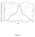
- FIG. 13 which will be discussed in more detail below, represents a curve of the sphere variation standardized to the addition along said circle of diameter 40 mm for the lens of FIG.
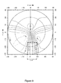
- Figure 3 shows a cylinder map of the lens of Figure 1.
- Figure 3 there is also shown the radius circle 20 mm centered at the geometric center (0,0) of the lens.
- the maximum value of the cylinder normalized to the addition C / A is equal to 0.78 in this circle with a radius of 20 mm centered on the geometric center of the lens, ie less than 0.8.
- the invention also proposes to introduce a constraint on the positions of the isocylinder lines equal to half the prescribed addition A / 2 in the lower part of the lens.
- the cylinder is representative of the gap between the local surface and a spherical surface; it is interesting that it remains weak in the area of the lens used for vision, which in geometric terms amounts to "spreading” or “widening” the isocylinder lines of the meridian.
- a horizontal width L VP is measured between the isocylinder lines of value A / 2, which corresponds to the width of the near vision zone.
- This width L VP is the difference of the x-coordinates of the two points of the two lines of isocylinder A / 2 whose ordinate is 18 mm lower than that of the mounting cross CM.
- the complex surface of the lens has a near-vision zone width L VP of between 11 mm and 15 mm, which corresponds to a near-vision zone that is well clear.
- the lens has a near vision width L VP equal to 13.11 mm.
- the invention proposes to also use a criterion of relative width in near vision LR VP , which takes into account the relative addition on the meridian A VP , the width of the near vision zone L VP (horizontal width at 1 isocylinder A / 2), and the maximum value of the cylinder C VP outside the near vision zone.
- This criterion of relative width is defined at a given ordinate, at 18 mm below the mounting cross CM. In the examples, this ordinate corresponds to the near-vision reference point VP.
- a VP is defined as the difference between the mean sphere on the main meridian of progression at the near-vision reference point VP and the mounting cross CM.
- LR VP The VP ⁇ AT VP / VS VP
- This relative width is representative not only of the width of the near vision area L VP , but also of the softness of the lens outside thereof, at 18 mm below the mounting cross CM.
- the near vision zone is defined so as to maximize the value of the relative width in near vision LR VP ; advantageously, it is greater than a value of the order of 15 mm, and this for all the additions. Isocylinders A / 2 are determined without the near vision zone so as to satisfy this condition.
- the relative width in near vision LR VP is equal to 17.12 mm.
- the invention further proposes to minimize in each useful point of the lens, the product of the sphere slope by the cylinder.
- This quantity is representative of the aberrations of the lens: it is clearly zero for a spherical lens.
- the sphere slope is representative of the local variations of the sphere, and is even weaker than the lens is "soft", ie it presents a progression which is not too much brutal.
- the product of the sphere slope by the cylinder represents a balance between the control of the slopes of sphere, and the will to widen the isocylinders.
- the product would be zero on the meridian, and have a low value around it.
- the cylinder values may increase, but the product may remain weak if the sphere slope itself is weak: this is preferable in areas far away from the meridian, since the sphere progression is actually functional only in the corridor of progression around the meridian.
- imposing a limit on the product of the sphere slope by the cylinder on the surface of the lens involves minimizing the cylinder in the foveal region, while minimizing the sphere slope in the extra-foveal region. It provides both good foveal vision, and good peripheral vision.
- the product of the sphere slope by the cylinder is therefore a representative amount of the aberrations on the surface of the lens.
- the invention proposes to minimize this product on the surface of the lens inside a circle with a radius of 20 mm around the center of the lens; this amounts to excluding the edge areas of the lens, which are only little or not used by the wearer, especially in the case of small frames.
- the invention proposes to introduce the criterion of a ratio between the integral of the product of the cylinder by the norm of the gradient of the sphere, on the circle of radius 20 mm centered on the center of the lens, d one hand and the product of the area of this circle, the addition and the maximum value of the norm of the gradient of the sphere on the part of the meridian included in this circle, on the other hand, less than 0 14.
- this criterion is 0.11.
- Figures 4 to 6 are views similar to those of Figures 1 to 3, but for a lens having a power addition of 2 diopters on the complex surface.
- Figure 4 shows the characteristics already highlighted in Figure 1 - except that the average sphere progression on the meridian is the order of 2 diopters and no more than 1.5 diopters. The values are shifted to zero at the origin, where the average sphere is actually 6.58 diopters.
- the solid line (the sphere) and the broken lines (the principal curvatures) are not merged - which is representative of a non-zero cylinder on the meridian of the lens.
- the construction cylinder was introduced to compensate for the optical aberrations generated by the lens positioned in the conditions worn and which can be simulated by ray tracing and analyzed in carrier power and astigmatism .
- the average sphere variation on the meridian in the upper part of the lens, between the CM mounting cross and the VL far vision reference point, is 0.04 diopters; and the mean sphere variation on the meridian below the near-vision reference point VP decreases slightly in order to compensate for the power variations generated by the actual conditions in the field of view.
- FIG. 4 also shows the progression length LP.
- the maximum slope of sphere variation normalized to the addition is equal to 0.082 mm -1 . It therefore greater than 0.07 mm -1 .
- Figure 5 shows the isosphere lines of 0 to 2 diopters, with a step of 0.25 diopters.
- Figure 2 there is shown a circle with a radius of 20 mm centered on the geometric center of the lens.
- the rebound in the variation of the value of the sphere along this circle, divided by the value of the addition A, is less than 0.04.
- Figure 14, which will be described later, represents a curve of the sphere variation normalized to the addition along this circle for this lens having a power addition of 2 diopters on the complex surface.
- FIG. 6 shows the isocylinder lines of 0.25 to 1.5 diopters, with a pitch of 0.25 diopters. As in Figure 3, we find that in the lower part of the lens, the isocylinder lines are almost parallel and vertical and delimit an area containing the reference point in near vision VP.
- FIG. 6 also shows the near vision width L VP; according to the definitions given with reference to FIG. 3, the near vision width L VP is equal to 13.02 mm and the relative width in near vision LR VP is equal to 17.72 mm.
- the 20 mm radius circle centered at the geometric center (0,0) of the lens has also been represented and it can be seen that the value of the C / A addition normalized roll is less than 0.8 in this circle. A maximum normalized cylinder value at the addition of 0.78 is measured.
- the lens of FIG. 6 also meets the criterion of a ratio between the integral of the product of the cylinder by the norm of the gradient of the sphere, on the circle of radius 20 mm centered on the center of the lens, one hand and the product of the area of this circle, the addition and the maximum value of the norm of the gradient of the sphere on the part of the meridian included in this circle, on the other hand, less than 0 14.
- the value measured for this ratio is 0.12.
- Figures 7 to 9 are views similar to those of Figures 4 to 6, but without special consideration of the conditions worn.
- the characteristics already shown in FIG. 1 are shown in FIG. 7, except that the average sphere progression on the meridian is of the order of 2 diopters and not more than 1.5 diopters.
- the average sphere at the origin is 6.57 diopters.
- the average sphere variation on the meridian in the upper part of the lens, between the CM mounting cross and the VL far vision reference point, is 0.04 diopters; and the mean sphere variation on the meridian below the near vision reference point VP decreases slightly.
- FIG. 7 also shows the progression length LP.
- the maximum slope of sphere variation normalized to the addition is equal to 0.078 mm -1 ; it therefore greater than 0.07 mm -1 .
- Figure 8 shows the isosphere lines of 0 to 2 diopters, with a step of 0.25 diopters.
- a circle with a radius of 20 mm centered on the geometric center of the lens.
- the rebound in the variation of the value of the sphere along this circle, divided by the value of the addition A, is less than 0.04.
- FIG. 15, which will be described later, represents a curve of the normalized sphere variation at the addition along this circle for this lens having a power addition of 2 diopters on the complex surface.
- Figure 9 shows the isocylinder lines of 0.25 to 1.5 diopters, with a pitch of 0.25 diopters. As in Figures 3 and 6, it is found that in the lower part of the lens, the isocylinder lines are almost parallel and vertical and define an area containing the reference point near vision VP.
- FIG. 9 also shows the near vision width L VP; according to the definitions given with reference to FIG. 3, the near vision width L VP is equal to 12.6 mm and the relative near-vision width LR VP is equal to 16.65 mm.
- the 20 mm radius circle centered at the geometric center (0,0) of the lens has also been represented and it can be seen that the value of the C / A addition normalized roll is less than 0.8 in this circle. A maximum normalized cylinder value at the addition of 0.76 is measured.
- the lens of FIG. 9 also meets the criterion of a ratio between the integral of the product of the cylinder by the norm of the gradient of the sphere, on the circle of radius 20 mm centered on the center of the lens, one hand and the product of the area of this circle, the addition and the maximum value of the norm of the gradient of the sphere on the part of the meridian included in this circle, on the other hand, less than 0 14.
- this criterion is 0.12.
- Figures 10 to 12 are views similar to those of Figures 1 to 3, but for a lens having a power addition of 2.5 diopters on the complex surface.
- the characteristics already shown in FIG. 1 are shown in FIG. 10, except that the average sphere progression on the meridian is of the order of 2.5 diopters and not more than 1.5 diopters.
- the average sphere at the origin is 6.55 diopters.
- the variation of mean sphere on the meridian in the part the top of the lens, between the CM mounting cross and the VL far vision reference point, is 0.05 diopters; and the mean sphere variation on the meridian below the near-vision reference point decreases slightly.
- FIG. 10 also shows the progression length LP.
- the maximum slope of sphere variation normalized to the addition is equal to 0.078 mm -1 ; it therefore greater than 0.07 mm -1 .
- Figure 11 shows the isosphere lines from 0 to 2.5 diopters, with a step of 0.25 diopters.
- Figure 2 there is shown a circle with a radius of 20 mm centered on the geometric center of the lens.
- the rebound in the variation of the value of the sphere along this circle, divided by the value of the addition A, is less than 0.04.
- FIG. 16, which will be described later, represents a curve of the normalized sphere variation at the addition along this circle for this lens having a power addition of 2.5 diopters on the complex surface.
- Figure 12 shows the isocylinder lines of 0.25 to 1.75 diopters, with a pitch of 0.25 diopters. As in Figures 3, 6 and 9, it is found that in the lower part of the lens, the isocylinder lines are almost parallel and vertical and define an area containing the reference point near vision VP.
- FIG. 12 also shows the near-vision width L VP; according to the definitions given with reference to FIG. 3, the near vision width L VP is equal to 12.61 mm and the relative width in near vision LR VP is equal to 16.64 mm.
- the 20 mm radius circle centered at the geometric center (0,0) of the lens has also been represented and it can be seen that the value of the C / A addition normalized roll is less than 0.8 in this circle. A maximum normalized cylinder value at the addition of 0.76 is measured.
- the lens of FIG. 12 also meets the criterion of a ratio between the integral of the product of the cylinder by the norm of the gradient of the sphere, on the circle of radius 20 mm centered on the center of the lens, on the one hand and the product of the area of this circle, the addition and the maximum value of the norm of the gradient of the sphere on the part of the meridian included in this circle, on the other hand, less than 0.14.
- the value of this ratio is 0.12.
- Figures 13 to 16 show the variation of the average sphere on the circle of diameter 40 mm centered on the geometric center of the lens, for the various lenses described above.
- the ordinates are graduated without units since the values are expressed in values of sphere (diopter) normalized to the addition (diopter).
- the abscissas represent the angle ⁇ in a polar coordinate system whose center is the geometric center of the lens and whose angles are measured from the vertical half-line upwards.
- Figures 13 to 16 show that the value of the sphere increases when one moves on the circle from a point of intersection of the circle with the meridian towards the other point of intersection of the circle with the meridian to reach an absolute maximum , then the value of the sphere decreases when one moves on the circle to return to the first point of intersection of the circle with the meridian to define an absolute minimum.
- the absolute maximum of the sphere normalized to the addition is reached for the point corresponding to the intersection of the circle with the meridian in the lower part of the lens (near vision zone).
- Each curve of the sphere variation normalized to the addition has two rebounds on either side of the absolute maximum. Each rebound is a break in the monotonous variation of the sphere.
- the evolution of the sphere on the circle of 20 mm radius centered on the geometric center of the lens has rebounds of very low amplitude when moving on the circle from a point of intersection from the circle with the meridian to the other point of intersection of the circle with the meridian; this low rebound of the sphere on the circle, on either side of the meridian, ensures a smooth and uniform variation of the optical characteristics of the lens and ensures greater ease of adaptation of the wearer to the lenses.
- the summary table below shows the characteristic values of the lenses according to the invention for different addition values.
- the progress length LP has been reported for different addition values; the maximum slope P max of the variation of the sphere normalized to the addition on the meridian; the maximum rebound of the sphere quantity normalized to the addition on the 20 mm radius circle centered on the geometric center of the lens; the maximum cylinder C max normalized to the addition in said circle; the average sphere difference on the meridian between the glass mounting cross and the far vision control point; the width of the near vision area L VP ; the normalized width of the LR VP near vision area; and the ratio R between the integral of the product of the cylinder by the norm of the gradient of the sphere, on the circle of radius 20 mm centered on the center of the lens, on the one hand and the product of the area of this circle , the addition and the maximum value of the norm of the gradient of the sphere on the part of the meridian included in this circle, on the other hand.
- Figures 1 to 16 illustrate four embodiments of lenses according to the invention. These figures show that the lens has good accessibility to the power required for near vision, the near vision zone being accessible from 14 mm under the mounting cross, and improved softness in the peripheral areas on either side of the meridian, with a maximum of normalized cylinder in the useful zone of the lens and a rebound of the sphere Normalized to the addition on the 40 mm diameter circle centered on the minimized lens.
- the lens according to the invention is prescribed by considering the carrier requirements in far vision and near vision which determines the necessary addition.
- the necessary power can be obtained, as in the state of the art, by machining a rear face to ensure that the power is identical to the prescribed power.
- the mounting of the lens in a visual equipment can be done in the following manner.
- the horizontal position of the pupil of the wearer in far vision is measured, ie the pupillary half-distance only, and the total height of the caliber of the frame of the visual equipment is determined.
- the lens is then mounted in the visual equipment with the mounting cross positioned at the measured position.
- the fitting of the lens therefore only requires a conventional measurement of the distance pupillary distance of vision, as well as a measurement of the height of the frame size, to determine the height at which the mounting cross must be placed. in the mount.
- Mounting the lens in the mount is simply by measuring the position in the frame of the gaze of the subject in far vision; this measurement is done in a classical way, the subject wearing the mount and looking at infinity. The lens is then turned away and mounted in the mount, so that the mounting cross is in the measured position.
- the lens according to the invention allows an improved tolerance to the assembly described above.
- This tolerance is provided by a value of the substantially constant sphere around the mounting cross.
- the average sphere difference on the meridian between the glass mounting cross and the far vision control point is less than 0.06 diopter.
Landscapes
- Health & Medical Sciences (AREA)
- Ophthalmology & Optometry (AREA)
- Physics & Mathematics (AREA)
- General Health & Medical Sciences (AREA)
- General Physics & Mathematics (AREA)
- Optics & Photonics (AREA)
- Eyeglasses (AREA)
- Compositions Of Oxide Ceramics (AREA)
- Prostheses (AREA)
- Materials For Medical Uses (AREA)
Priority Applications (1)
| Application Number | Priority Date | Filing Date | Title |
|---|---|---|---|
| PL06290652T PL1744202T3 (pl) | 2005-07-11 | 2006-04-21 | Soczewka okularowa |
Applications Claiming Priority (1)
| Application Number | Priority Date | Filing Date | Title |
|---|---|---|---|
| FR0507378A FR2888344B1 (fr) | 2005-07-11 | 2005-07-11 | Lentille ophtalmique |
Publications (2)
| Publication Number | Publication Date |
|---|---|
| EP1744202A1 true EP1744202A1 (de) | 2007-01-17 |
| EP1744202B1 EP1744202B1 (de) | 2009-02-25 |
Family
ID=36118084
Family Applications (1)
| Application Number | Title | Priority Date | Filing Date |
|---|---|---|---|
| EP06290652A Expired - Lifetime EP1744202B1 (de) | 2005-07-11 | 2006-04-21 | Progressive Brillenlinse |
Country Status (15)
| Country | Link |
|---|---|
| US (1) | US7413303B2 (de) |
| EP (1) | EP1744202B1 (de) |
| JP (1) | JP4991713B2 (de) |
| KR (1) | KR101275524B1 (de) |
| CN (1) | CN101273299B (de) |
| AT (1) | ATE423989T1 (de) |
| AU (1) | AU2006267926B2 (de) |
| BR (2) | BRPI0800407A (de) |
| CA (1) | CA2614910C (de) |
| DE (1) | DE602006005287D1 (de) |
| ES (1) | ES2323088T3 (de) |
| FR (1) | FR2888344B1 (de) |
| PL (1) | PL1744202T3 (de) |
| PT (1) | PT1744202E (de) |
| WO (1) | WO2007007209A2 (de) |
Cited By (4)
| Publication number | Priority date | Publication date | Assignee | Title |
|---|---|---|---|---|
| FR2924825A1 (fr) * | 2007-12-11 | 2009-06-12 | Essilor Int | Lentille ophtalmique progressive. |
| WO2009103175A3 (fr) * | 2008-02-20 | 2009-10-29 | Swissphonics Sa | Lentilles ophtalmiques multifocales progressives optimisées à l'identique sur une large gamme de valeurs d'indices de réfraction, de basecurves, et d'additions |
| FR2956222A1 (fr) * | 2010-02-09 | 2011-08-12 | Essilor Int | Lentille ophtalmique multifocale progressive |
| FR2956223A1 (fr) * | 2010-02-09 | 2011-08-12 | Essilor Int | Lentille ophtalmique multifocale progressive |
Families Citing this family (13)
| Publication number | Priority date | Publication date | Assignee | Title |
|---|---|---|---|---|
| FR2894038B1 (fr) * | 2005-11-29 | 2008-03-07 | Essilor Int | Lentille ophtalmique. |
| FR2924824B1 (fr) * | 2007-12-05 | 2010-03-26 | Essilor Int | Lentille progressive de lunettes ophtalmiques ayant une zone supplementaire de vision intermediaire |
| FR2945874A1 (fr) * | 2009-05-20 | 2010-11-26 | Essilor Int | Lentille ophtalmique de type unifocale |
| CN102792211B (zh) | 2010-01-18 | 2014-10-29 | 依视路国际集团(光学总公司) | 设计眼科渐进镜片的方法 |
| US8042941B2 (en) * | 2010-01-29 | 2011-10-25 | Indizen Optical Technologies, S.I. | Lens with continuous power gradation |
| AU2011361299B2 (en) * | 2011-03-07 | 2015-08-20 | Essilor International | A method for determining a progressive ophthalmic lens |
| ES2927468T3 (es) * | 2012-03-14 | 2022-11-07 | Holden Brien Vision Inst | Lente para ojo miope |
| TWI588560B (zh) | 2012-04-05 | 2017-06-21 | 布萊恩荷登視覺協會 | 用於屈光不正之鏡片、裝置、方法及系統 |
| CN103487946B (zh) * | 2012-06-11 | 2016-02-10 | 苏州苏大明世光学股份有限公司 | 宽屏智能老花镜片及其制备模具 |
| US9201250B2 (en) | 2012-10-17 | 2015-12-01 | Brien Holden Vision Institute | Lenses, devices, methods and systems for refractive error |
| HK1212194A1 (en) | 2012-10-17 | 2016-06-10 | Brien Holden Vision Institute | Lenses, devices, methods and systems for refractive error |
| TWI626491B (zh) * | 2012-12-10 | 2018-06-11 | 布萊恩荷登視覺協會 | 用於視力校正之具有一或多個多正焦區域之眼用光學透鏡 |
| US11209671B2 (en) * | 2018-08-20 | 2021-12-28 | Shamir Optical Industry Ltd. | Progressive optical designs for different add powers |
Citations (7)
| Publication number | Priority date | Publication date | Assignee | Title |
|---|---|---|---|---|
| FR2769998A1 (fr) * | 1997-10-16 | 1999-04-23 | Essilor Int | Lentille ophtalmique multifocale |
| FR2769999A1 (fr) * | 1997-10-16 | 1999-04-23 | Essilor Int | Lentille ophtalmique multifocale |
| US6102544A (en) * | 1997-10-16 | 2000-08-15 | Essilor International | Multifocal ophthalmic lens |
| FR2809193A1 (fr) * | 2000-05-16 | 2001-11-23 | Essilor Int | Lentille ophtalmique multifocale progressive a variation de puissance rapide |
| FR2820516A1 (fr) * | 2001-02-02 | 2002-08-09 | Essilor Int | Lentille ophtalmique multifocale progressive a variation de puissance rapide |
| FR2820515A1 (fr) * | 2001-02-02 | 2002-08-09 | Essilor Int | Lentille ophtalmique multifocale progressive a variation de puissance rapide |
| US20030156251A1 (en) * | 2000-04-25 | 2003-08-21 | Optische Werke G. Rodenstock | Progressive spectacle lens with low swaying effects |
Family Cites Families (16)
| Publication number | Priority date | Publication date | Assignee | Title |
|---|---|---|---|---|
| US4307945A (en) * | 1980-02-14 | 1981-12-29 | Itek Corporation | Progressively varying focal power opthalmic lens |
| FR2588973B1 (fr) * | 1985-10-23 | 1988-01-08 | Essilor Int | Lentille ophtalmique progressive |
| FR2683643B1 (fr) * | 1991-11-12 | 1994-01-14 | Essilor Internal Cie Gle Optique | Lentille ophtalmique multifocale progressive. |
| FR2683642B1 (fr) * | 1991-11-12 | 1994-01-14 | Essilor Internal Cie Gle Optique | Lentille ophtalmique multifocale progressive. |
| FR2699294B1 (fr) | 1992-12-11 | 1995-02-10 | Essilor Int | Lentille ophtalmique multifocale progressive. |
| FR2704327B1 (fr) | 1993-04-23 | 1995-06-23 | Essilor Int | Paire de lentilles ophtalmiques multifocales progressives. |
| FR2753805B1 (fr) | 1996-09-20 | 1998-11-13 | Essilor Int | Jeu de lentilles ophtalmiques multifocales progressives |
| AUPO903197A0 (en) * | 1997-09-09 | 1997-10-02 | Sola International Holdings Ltd | Improved progressive lens |
| FR2769997B1 (fr) | 1997-10-16 | 1999-12-31 | Essilor Int | Lentille ophtalmique multifocale |
| US6540354B2 (en) * | 1997-10-16 | 2003-04-01 | Essilor International | Multifocal ophthalmic lens |
| FR2770000B1 (fr) | 1997-10-16 | 1999-12-31 | Essilor Int | Lentille ophtalmique multifocale |
| FR2783938B1 (fr) * | 1998-09-28 | 2000-11-17 | Essilor Int | Lentilles ophtalmiques toriques |
| AUPQ065599A0 (en) * | 1999-05-31 | 1999-06-24 | Sola International Holdings Ltd | Progressive lens |
| EP1216432B1 (de) * | 1999-10-01 | 2009-03-04 | Carl Zeiss Vision Australia Holdings Ltd. | Progressive linse |
| JP4481647B2 (ja) | 2001-12-05 | 2010-06-16 | カール ツァイス ビジョン オーストラリア ホールディングス リミテッド | バランスされた累進レンズ |
| CN1510456A (zh) * | 2002-12-26 | 2004-07-07 | 薛广顺 | 一种眼镜 |
-
2005
- 2005-07-11 FR FR0507378A patent/FR2888344B1/fr not_active Expired - Lifetime
-
2006
- 2006-04-21 ES ES06290652T patent/ES2323088T3/es not_active Expired - Lifetime
- 2006-04-21 EP EP06290652A patent/EP1744202B1/de not_active Expired - Lifetime
- 2006-04-21 PT PT06290652T patent/PT1744202E/pt unknown
- 2006-04-21 DE DE602006005287T patent/DE602006005287D1/de not_active Expired - Lifetime
- 2006-04-21 AT AT06290652T patent/ATE423989T1/de not_active IP Right Cessation
- 2006-04-21 PL PL06290652T patent/PL1744202T3/pl unknown
- 2006-06-08 US US11/449,150 patent/US7413303B2/en active Active
- 2006-07-06 AU AU2006267926A patent/AU2006267926B2/en active Active
- 2006-07-06 BR BRPI0800407-2A patent/BRPI0800407A/pt unknown
- 2006-07-06 WO PCT/IB2006/002763 patent/WO2007007209A2/en not_active Ceased
- 2006-07-06 BR BRPI0621494-0A patent/BRPI0621494B1/pt active IP Right Grant
- 2006-07-06 KR KR1020087000481A patent/KR101275524B1/ko active Active
- 2006-07-06 JP JP2008520983A patent/JP4991713B2/ja active Active
- 2006-07-06 CN CN2006800254711A patent/CN101273299B/zh active Active
- 2006-07-06 CA CA2614910A patent/CA2614910C/en active Active
Patent Citations (7)
| Publication number | Priority date | Publication date | Assignee | Title |
|---|---|---|---|---|
| FR2769998A1 (fr) * | 1997-10-16 | 1999-04-23 | Essilor Int | Lentille ophtalmique multifocale |
| FR2769999A1 (fr) * | 1997-10-16 | 1999-04-23 | Essilor Int | Lentille ophtalmique multifocale |
| US6102544A (en) * | 1997-10-16 | 2000-08-15 | Essilor International | Multifocal ophthalmic lens |
| US20030156251A1 (en) * | 2000-04-25 | 2003-08-21 | Optische Werke G. Rodenstock | Progressive spectacle lens with low swaying effects |
| FR2809193A1 (fr) * | 2000-05-16 | 2001-11-23 | Essilor Int | Lentille ophtalmique multifocale progressive a variation de puissance rapide |
| FR2820516A1 (fr) * | 2001-02-02 | 2002-08-09 | Essilor Int | Lentille ophtalmique multifocale progressive a variation de puissance rapide |
| FR2820515A1 (fr) * | 2001-02-02 | 2002-08-09 | Essilor Int | Lentille ophtalmique multifocale progressive a variation de puissance rapide |
Cited By (9)
| Publication number | Priority date | Publication date | Assignee | Title |
|---|---|---|---|---|
| FR2924825A1 (fr) * | 2007-12-11 | 2009-06-12 | Essilor Int | Lentille ophtalmique progressive. |
| WO2009080979A3 (fr) * | 2007-12-11 | 2009-08-20 | Essilor Int | Lentille ophtalmique progressive |
| US8186829B2 (en) | 2007-12-11 | 2012-05-29 | Essilor International (Compagnie Generale D'optique) | Progressive ophthalmic lens |
| AU2008339801B2 (en) * | 2007-12-11 | 2014-02-20 | Essilor International | Progressive ophthalmic lens |
| WO2009103175A3 (fr) * | 2008-02-20 | 2009-10-29 | Swissphonics Sa | Lentilles ophtalmiques multifocales progressives optimisées à l'identique sur une large gamme de valeurs d'indices de réfraction, de basecurves, et d'additions |
| FR2956222A1 (fr) * | 2010-02-09 | 2011-08-12 | Essilor Int | Lentille ophtalmique multifocale progressive |
| FR2956223A1 (fr) * | 2010-02-09 | 2011-08-12 | Essilor Int | Lentille ophtalmique multifocale progressive |
| WO2011098951A1 (fr) * | 2010-02-09 | 2011-08-18 | Essilor International (Compagnie Générale d'Optique) | Lentille ophtalmique multifocale progressive |
| WO2011098952A1 (fr) * | 2010-02-09 | 2011-08-18 | Essilor International (Compagnie Générale d'Optique) | Lentille ophtalmique multifocale progressive |
Also Published As
| Publication number | Publication date |
|---|---|
| KR101275524B1 (ko) | 2013-06-20 |
| WO2007007209A3 (en) | 2007-03-29 |
| JP2009543100A (ja) | 2009-12-03 |
| BRPI0621494A2 (pt) | 2009-03-10 |
| CA2614910A1 (en) | 2007-01-18 |
| WO2007007209A8 (en) | 2008-05-29 |
| KR20080023339A (ko) | 2008-03-13 |
| AU2006267926A1 (en) | 2007-01-18 |
| CA2614910C (en) | 2014-10-28 |
| PL1744202T3 (pl) | 2009-08-31 |
| ES2323088T3 (es) | 2009-07-06 |
| US20070008489A1 (en) | 2007-01-11 |
| FR2888344A1 (fr) | 2007-01-12 |
| WO2007007209A2 (en) | 2007-01-18 |
| AU2006267926B2 (en) | 2011-02-03 |
| ATE423989T1 (de) | 2009-03-15 |
| EP1744202B1 (de) | 2009-02-25 |
| CN101273299B (zh) | 2011-05-25 |
| BRPI0621494B1 (pt) | 2018-05-29 |
| JP4991713B2 (ja) | 2012-08-01 |
| DE602006005287D1 (de) | 2009-04-09 |
| FR2888344B1 (fr) | 2007-09-14 |
| BRPI0800407A (pt) | 2008-07-15 |
| PT1744202E (pt) | 2009-05-12 |
| US7413303B2 (en) | 2008-08-19 |
| CN101273299A (zh) | 2008-09-24 |
Similar Documents
| Publication | Publication Date | Title |
|---|---|---|
| EP1744202B1 (de) | Progressive Brillenlinse | |
| EP0990939B2 (de) | Torische ophthalmische Linsen | |
| EP1960825B1 (de) | Verfahrn zur bestimmung eines satzes progressiver multifokal-brillengläser | |
| EP2251733B1 (de) | Ophthalmische Linse | |
| EP2087396B1 (de) | Verfahren zur bestimmung eines brillenglases | |
| FR2912820A1 (fr) | Realisation d'un element ophtalmique adapte pour les visions foveale et peripherique | |
| EP2433177B1 (de) | Berechnungsmethode einer ophthalmischen linse von der unifocalen art | |
| CA2566981C (fr) | Lentille ophtalmique pour limiter la fatigue visuelle des porteurs esophores et non presbytes | |
| EP2470941B1 (de) | Verfahren zur bestimmung, optimierung und herstellung einer ophthalmischen linse und satz aus ophthalmischen linsen | |
| EP1960826B1 (de) | Verfahren zur bestimmung eines progressiven brillenglases | |
| EP2249195B1 (de) | Ophthalmische Linse | |
| FR2898993A1 (fr) | Procede de determination d'une lentille ophtalmique progressive | |
| WO2008065266A1 (fr) | Lentille ophtalmique | |
| EP2302442A1 (de) | Verfahren zur Bestimmung einer Brillenlinse | |
| EP1851582B1 (de) | Verfahren zum definieren einer ergänzungsvorderseite für brillen | |
| EP1869522B1 (de) | Augenoptische linse | |
| EP1756654B1 (de) | Progressives brillenglas | |
| EP2534529B1 (de) | Gleitsichtlinse | |
| FR2996316A1 (fr) | Lentille ophtalmique progressive pour patient souffrant de deficience visuelle |
Legal Events
| Date | Code | Title | Description |
|---|---|---|---|
| PUAI | Public reference made under article 153(3) epc to a published international application that has entered the european phase |
Free format text: ORIGINAL CODE: 0009012 |
|
| AK | Designated contracting states |
Kind code of ref document: A1 Designated state(s): AT BE BG CH CY CZ DE DK EE ES FI FR GB GR HU IE IS IT LI LT LU LV MC NL PL PT RO SE SI SK TR |
|
| AX | Request for extension of the european patent |
Extension state: AL BA HR MK YU |
|
| 17P | Request for examination filed |
Effective date: 20070717 |
|
| 17Q | First examination report despatched |
Effective date: 20070820 |
|
| AKX | Designation fees paid |
Designated state(s): AT BE BG CH CY CZ DE DK EE ES FI FR GB GR HU IE IS IT LI LT LU LV MC NL PL PT RO SE SI SK TR |
|
| GRAP | Despatch of communication of intention to grant a patent |
Free format text: ORIGINAL CODE: EPIDOSNIGR1 |
|
| RIC1 | Information provided on ipc code assigned before grant |
Ipc: G02C 7/02 20060101AFI20080910BHEP Ipc: G02C 7/06 20060101ALI20080910BHEP |
|
| GRAS | Grant fee paid |
Free format text: ORIGINAL CODE: EPIDOSNIGR3 |
|
| GRAA | (expected) grant |
Free format text: ORIGINAL CODE: 0009210 |
|
| AK | Designated contracting states |
Kind code of ref document: B1 Designated state(s): AT BE BG CH CY CZ DE DK EE ES FI FR GB GR HU IE IS IT LI LT LU LV MC NL PL PT RO SE SI SK TR |
|
| REG | Reference to a national code |
Ref country code: GB Ref legal event code: FG4D Free format text: NOT ENGLISH |
|
| REG | Reference to a national code |
Ref country code: CH Ref legal event code: EP |
|
| REG | Reference to a national code |
Ref country code: IE Ref legal event code: FG4D Free format text: LANGUAGE OF EP DOCUMENT: FRENCH |
|
| REF | Corresponds to: |
Ref document number: 602006005287 Country of ref document: DE Date of ref document: 20090409 Kind code of ref document: P |
|
| REG | Reference to a national code |
Ref country code: CH Ref legal event code: NV Representative=s name: ZIMMERLI, WAGNER & PARTNER AG |
|
| REG | Reference to a national code |
Ref country code: PT Ref legal event code: SC4A Free format text: AVAILABILITY OF NATIONAL TRANSLATION Effective date: 20090505 |
|
| REG | Reference to a national code |
Ref country code: SE Ref legal event code: TRGR |
|
| REG | Reference to a national code |
Ref country code: ES Ref legal event code: FG2A Ref document number: 2323088 Country of ref document: ES Kind code of ref document: T3 |
|
| PG25 | Lapsed in a contracting state [announced via postgrant information from national office to epo] |
Ref country code: LT Free format text: LAPSE BECAUSE OF FAILURE TO SUBMIT A TRANSLATION OF THE DESCRIPTION OR TO PAY THE FEE WITHIN THE PRESCRIBED TIME-LIMIT Effective date: 20090225 Ref country code: SI Free format text: LAPSE BECAUSE OF FAILURE TO SUBMIT A TRANSLATION OF THE DESCRIPTION OR TO PAY THE FEE WITHIN THE PRESCRIBED TIME-LIMIT Effective date: 20090225 Ref country code: FI Free format text: LAPSE BECAUSE OF FAILURE TO SUBMIT A TRANSLATION OF THE DESCRIPTION OR TO PAY THE FEE WITHIN THE PRESCRIBED TIME-LIMIT Effective date: 20090225 |
|
| PG25 | Lapsed in a contracting state [announced via postgrant information from national office to epo] |
Ref country code: IS Free format text: LAPSE BECAUSE OF FAILURE TO SUBMIT A TRANSLATION OF THE DESCRIPTION OR TO PAY THE FEE WITHIN THE PRESCRIBED TIME-LIMIT Effective date: 20090625 Ref country code: AT Free format text: LAPSE BECAUSE OF FAILURE TO SUBMIT A TRANSLATION OF THE DESCRIPTION OR TO PAY THE FEE WITHIN THE PRESCRIBED TIME-LIMIT Effective date: 20090225 Ref country code: LV Free format text: LAPSE BECAUSE OF FAILURE TO SUBMIT A TRANSLATION OF THE DESCRIPTION OR TO PAY THE FEE WITHIN THE PRESCRIBED TIME-LIMIT Effective date: 20090225 |
|
| REG | Reference to a national code |
Ref country code: PL Ref legal event code: T3 |
|
| REG | Reference to a national code |
Ref country code: IE Ref legal event code: FD4D |
|
| PG25 | Lapsed in a contracting state [announced via postgrant information from national office to epo] |
Ref country code: EE Free format text: LAPSE BECAUSE OF FAILURE TO SUBMIT A TRANSLATION OF THE DESCRIPTION OR TO PAY THE FEE WITHIN THE PRESCRIBED TIME-LIMIT Effective date: 20090225 Ref country code: CZ Free format text: LAPSE BECAUSE OF FAILURE TO SUBMIT A TRANSLATION OF THE DESCRIPTION OR TO PAY THE FEE WITHIN THE PRESCRIBED TIME-LIMIT Effective date: 20090225 Ref country code: IE Free format text: LAPSE BECAUSE OF FAILURE TO SUBMIT A TRANSLATION OF THE DESCRIPTION OR TO PAY THE FEE WITHIN THE PRESCRIBED TIME-LIMIT Effective date: 20090225 Ref country code: DK Free format text: LAPSE BECAUSE OF FAILURE TO SUBMIT A TRANSLATION OF THE DESCRIPTION OR TO PAY THE FEE WITHIN THE PRESCRIBED TIME-LIMIT Effective date: 20090225 |
|
| BERE | Be: lapsed |
Owner name: ESSILOR INTERNATIONAL (COMPAGNIE GENERALE D'OPTIQ Effective date: 20090430 |
|
| REG | Reference to a national code |
Ref country code: CH Ref legal event code: PFA Owner name: ESSILOR INTERNATIONAL (COMPAGNIE GENERALE D'OPTIQ Free format text: ESSILOR INTERNATIONAL (COMPAGNIE GENERALE D'OPTIQUE)#147 RUE DE PARIS#94227 CHARENTON CEDEX (FR) -TRANSFER TO- ESSILOR INTERNATIONAL (COMPAGNIE GENERALE D'OPTIQUE)#147 RUE DE PARIS#94227 CHARENTON CEDEX (FR) |
|
| PG25 | Lapsed in a contracting state [announced via postgrant information from national office to epo] |
Ref country code: SK Free format text: LAPSE BECAUSE OF FAILURE TO SUBMIT A TRANSLATION OF THE DESCRIPTION OR TO PAY THE FEE WITHIN THE PRESCRIBED TIME-LIMIT Effective date: 20090225 Ref country code: RO Free format text: LAPSE BECAUSE OF FAILURE TO SUBMIT A TRANSLATION OF THE DESCRIPTION OR TO PAY THE FEE WITHIN THE PRESCRIBED TIME-LIMIT Effective date: 20090225 |
|
| PLBE | No opposition filed within time limit |
Free format text: ORIGINAL CODE: 0009261 |
|
| STAA | Information on the status of an ep patent application or granted ep patent |
Free format text: STATUS: NO OPPOSITION FILED WITHIN TIME LIMIT |
|
| PG25 | Lapsed in a contracting state [announced via postgrant information from national office to epo] |
Ref country code: BG Free format text: LAPSE BECAUSE OF FAILURE TO SUBMIT A TRANSLATION OF THE DESCRIPTION OR TO PAY THE FEE WITHIN THE PRESCRIBED TIME-LIMIT Effective date: 20090525 |
|
| 26N | No opposition filed |
Effective date: 20091126 |
|
| PG25 | Lapsed in a contracting state [announced via postgrant information from national office to epo] |
Ref country code: MC Free format text: LAPSE BECAUSE OF NON-PAYMENT OF DUE FEES Effective date: 20090430 |
|
| PG25 | Lapsed in a contracting state [announced via postgrant information from national office to epo] |
Ref country code: BE Free format text: LAPSE BECAUSE OF NON-PAYMENT OF DUE FEES Effective date: 20090430 |
|
| PG25 | Lapsed in a contracting state [announced via postgrant information from national office to epo] |
Ref country code: GR Free format text: LAPSE BECAUSE OF FAILURE TO SUBMIT A TRANSLATION OF THE DESCRIPTION OR TO PAY THE FEE WITHIN THE PRESCRIBED TIME-LIMIT Effective date: 20090526 |
|
| PG25 | Lapsed in a contracting state [announced via postgrant information from national office to epo] |
Ref country code: LU Free format text: LAPSE BECAUSE OF NON-PAYMENT OF DUE FEES Effective date: 20090421 |
|
| PG25 | Lapsed in a contracting state [announced via postgrant information from national office to epo] |
Ref country code: HU Free format text: LAPSE BECAUSE OF FAILURE TO SUBMIT A TRANSLATION OF THE DESCRIPTION OR TO PAY THE FEE WITHIN THE PRESCRIBED TIME-LIMIT Effective date: 20090826 |
|
| PG25 | Lapsed in a contracting state [announced via postgrant information from national office to epo] |
Ref country code: TR Free format text: LAPSE BECAUSE OF FAILURE TO SUBMIT A TRANSLATION OF THE DESCRIPTION OR TO PAY THE FEE WITHIN THE PRESCRIBED TIME-LIMIT Effective date: 20090225 |
|
| PG25 | Lapsed in a contracting state [announced via postgrant information from national office to epo] |
Ref country code: CY Free format text: LAPSE BECAUSE OF FAILURE TO SUBMIT A TRANSLATION OF THE DESCRIPTION OR TO PAY THE FEE WITHIN THE PRESCRIBED TIME-LIMIT Effective date: 20090225 |
|
| REG | Reference to a national code |
Ref country code: CH Ref legal event code: NV Representative=s name: WAGNER PATENT AG, CH |
|
| REG | Reference to a national code |
Ref country code: FR Ref legal event code: PLFP Year of fee payment: 10 |
|
| PGFP | Annual fee paid to national office [announced via postgrant information from national office to epo] |
Ref country code: SE Payment date: 20150429 Year of fee payment: 10 |
|
| REG | Reference to a national code |
Ref country code: FR Ref legal event code: PLFP Year of fee payment: 11 |
|
| REG | Reference to a national code |
Ref country code: SE Ref legal event code: EUG |
|
| PG25 | Lapsed in a contracting state [announced via postgrant information from national office to epo] |
Ref country code: SE Free format text: LAPSE BECAUSE OF NON-PAYMENT OF DUE FEES Effective date: 20160422 |
|
| REG | Reference to a national code |
Ref country code: FR Ref legal event code: PLFP Year of fee payment: 12 |
|
| REG | Reference to a national code |
Ref country code: NL Ref legal event code: PD Owner name: ESSILOR INTERNATIONAL; FR Free format text: DETAILS ASSIGNMENT: CHANGE OF OWNER(S), ASSIGNMENT; FORMER OWNER NAME: ESSILOR INTERNATIONAL, COMPAGNIE GENERALE D'OPTIQUE Effective date: 20180219 |
|
| REG | Reference to a national code |
Ref country code: DE Ref legal event code: R082 Ref document number: 602006005287 Country of ref document: DE Representative=s name: 24IP LAW GROUP SONNENBERG FORTMANN, DE Ref country code: DE Ref legal event code: R081 Ref document number: 602006005287 Country of ref document: DE Owner name: ESSILOR INTERNATIONAL, FR Free format text: FORMER OWNER: ESSILOR INTERNATIONAL COMPAGNIE GENERALE D'OPTIQUE, CHARENTON, FR |
|
| REG | Reference to a national code |
Ref country code: FR Ref legal event code: PLFP Year of fee payment: 13 |
|
| REG | Reference to a national code |
Ref country code: ES Ref legal event code: PC2A Effective date: 20180521 Ref country code: ES Ref legal event code: PC2A Owner name: ESSILOR INTERNATIONAL Effective date: 20180521 |
|
| REG | Reference to a national code |
Ref country code: CH Ref legal event code: PUE Owner name: ESSILOR INTERNATIONAL, FR Free format text: FORMER OWNER: ESSILOR INTERNATIONAL (COMPAGNIE GENERALE D'OPTIQUE), FR |
|
| REG | Reference to a national code |
Ref country code: GB Ref legal event code: 732E Free format text: REGISTERED BETWEEN 20180517 AND 20180523 |
|
| REG | Reference to a national code |
Ref country code: FR Ref legal event code: TP Owner name: ESSILOR INTERNATIONAL, FR Effective date: 20180601 |
|
| P01 | Opt-out of the competence of the unified patent court (upc) registered |
Effective date: 20230525 |
|
| REG | Reference to a national code |
Ref country code: DE Ref legal event code: R082 Ref document number: 602006005287 Country of ref document: DE Representative=s name: SONNENBERG HARRISON PARTNERSCHAFT MBB PATENT- , DE |
|
| PGFP | Annual fee paid to national office [announced via postgrant information from national office to epo] |
Ref country code: NL Payment date: 20250427 Year of fee payment: 20 |
|
| PGFP | Annual fee paid to national office [announced via postgrant information from national office to epo] |
Ref country code: PL Payment date: 20250407 Year of fee payment: 20 Ref country code: DE Payment date: 20250429 Year of fee payment: 20 |
|
| PGFP | Annual fee paid to national office [announced via postgrant information from national office to epo] |
Ref country code: GB Payment date: 20250428 Year of fee payment: 20 Ref country code: ES Payment date: 20250505 Year of fee payment: 20 |
|
| PGFP | Annual fee paid to national office [announced via postgrant information from national office to epo] |
Ref country code: IT Payment date: 20250422 Year of fee payment: 20 |
|
| PGFP | Annual fee paid to national office [announced via postgrant information from national office to epo] |
Ref country code: PT Payment date: 20250402 Year of fee payment: 20 |
|
| PGFP | Annual fee paid to national office [announced via postgrant information from national office to epo] |
Ref country code: FR Payment date: 20250425 Year of fee payment: 20 |
|
| PGFP | Annual fee paid to national office [announced via postgrant information from national office to epo] |
Ref country code: CH Payment date: 20250501 Year of fee payment: 20 |
|
| REG | Reference to a national code |
Ref country code: CH Ref legal event code: H14 Free format text: ST27 STATUS EVENT CODE: U-0-0-H10-H14 (AS PROVIDED BY THE NATIONAL OFFICE) Effective date: 20260421 Ref country code: DE Ref legal event code: R071 Ref document number: 602006005287 Country of ref document: DE |