EP1744444B1 - dispositif de réglage du pas pour pale de rotor - Google Patents
dispositif de réglage du pas pour pale de rotor Download PDFInfo
- Publication number
- EP1744444B1 EP1744444B1 EP05015194A EP05015194A EP1744444B1 EP 1744444 B1 EP1744444 B1 EP 1744444B1 EP 05015194 A EP05015194 A EP 05015194A EP 05015194 A EP05015194 A EP 05015194A EP 1744444 B1 EP1744444 B1 EP 1744444B1
- Authority
- EP
- European Patent Office
- Prior art keywords
- winding
- field winding
- wind energy
- torque
- actuating motor
- Prior art date
- Legal status (The legal status is an assumption and is not a legal conclusion. Google has not performed a legal analysis and makes no representation as to the accuracy of the status listed.)
- Expired - Lifetime
Links
Images


Classifications
-
- F—MECHANICAL ENGINEERING; LIGHTING; HEATING; WEAPONS; BLASTING
- F03—MACHINES OR ENGINES FOR LIQUIDS; WIND, SPRING, OR WEIGHT MOTORS; PRODUCING MECHANICAL POWER OR A REACTIVE PROPULSIVE THRUST, NOT OTHERWISE PROVIDED FOR
- F03D—WIND MOTORS
- F03D7/00—Controlling wind motors
- F03D7/02—Controlling wind motors the wind motors having rotation axis substantially parallel to the air flow entering the rotor
- F03D7/022—Adjusting aerodynamic properties of the blades
- F03D7/0224—Adjusting blade pitch
-
- H—ELECTRICITY
- H02—GENERATION; CONVERSION OR DISTRIBUTION OF ELECTRIC POWER
- H02P—CONTROL OR REGULATION OF ELECTRIC MOTORS, ELECTRIC GENERATORS OR DYNAMO-ELECTRIC CONVERTERS; CONTROLLING TRANSFORMERS, REACTORS OR CHOKE COILS
- H02P3/00—Arrangements for stopping or slowing electric motors, generators, or dynamo-electric converters
- H02P3/06—Arrangements for stopping or slowing electric motors, generators, or dynamo-electric converters for stopping or slowing an individual dynamo-electric motor or dynamo-electric converter
- H02P3/08—Arrangements for stopping or slowing electric motors, generators, or dynamo-electric converters for stopping or slowing an individual dynamo-electric motor or dynamo-electric converter for stopping or slowing a DC motor
- H02P3/10—Arrangements for stopping or slowing electric motors, generators, or dynamo-electric converters for stopping or slowing an individual dynamo-electric motor or dynamo-electric converter for stopping or slowing a DC motor by reversal of supply connections
-
- H—ELECTRICITY
- H02—GENERATION; CONVERSION OR DISTRIBUTION OF ELECTRIC POWER
- H02P—CONTROL OR REGULATION OF ELECTRIC MOTORS, ELECTRIC GENERATORS OR DYNAMO-ELECTRIC CONVERTERS; CONTROLLING TRANSFORMERS, REACTORS OR CHOKE COILS
- H02P3/00—Arrangements for stopping or slowing electric motors, generators, or dynamo-electric converters
- H02P3/06—Arrangements for stopping or slowing electric motors, generators, or dynamo-electric converters for stopping or slowing an individual dynamo-electric motor or dynamo-electric converter
- H02P3/08—Arrangements for stopping or slowing electric motors, generators, or dynamo-electric converters for stopping or slowing an individual dynamo-electric motor or dynamo-electric converter for stopping or slowing a DC motor
- H02P3/14—Arrangements for stopping or slowing electric motors, generators, or dynamo-electric converters for stopping or slowing an individual dynamo-electric motor or dynamo-electric converter for stopping or slowing a DC motor by regenerative braking
-
- H—ELECTRICITY
- H02—GENERATION; CONVERSION OR DISTRIBUTION OF ELECTRIC POWER
- H02P—CONTROL OR REGULATION OF ELECTRIC MOTORS, ELECTRIC GENERATORS OR DYNAMO-ELECTRIC CONVERTERS; CONTROLLING TRANSFORMERS, REACTORS OR CHOKE COILS
- H02P7/00—Arrangements for regulating or controlling the speed or torque of electric DC motors
- H02P7/06—Arrangements for regulating or controlling the speed or torque of electric DC motors for regulating or controlling an individual DC dynamo-electric motor by varying field or armature current
- H02P7/18—Arrangements for regulating or controlling the speed or torque of electric DC motors for regulating or controlling an individual DC dynamo-electric motor by varying field or armature current by master control with auxiliary power
- H02P7/24—Arrangements for regulating or controlling the speed or torque of electric DC motors for regulating or controlling an individual DC dynamo-electric motor by varying field or armature current by master control with auxiliary power using discharge tubes or semiconductor devices
- H02P7/28—Arrangements for regulating or controlling the speed or torque of electric DC motors for regulating or controlling an individual DC dynamo-electric motor by varying field or armature current by master control with auxiliary power using discharge tubes or semiconductor devices using semiconductor devices
-
- Y—GENERAL TAGGING OF NEW TECHNOLOGICAL DEVELOPMENTS; GENERAL TAGGING OF CROSS-SECTIONAL TECHNOLOGIES SPANNING OVER SEVERAL SECTIONS OF THE IPC; TECHNICAL SUBJECTS COVERED BY FORMER USPC CROSS-REFERENCE ART COLLECTIONS [XRACs] AND DIGESTS
- Y02—TECHNOLOGIES OR APPLICATIONS FOR MITIGATION OR ADAPTATION AGAINST CLIMATE CHANGE
- Y02E—REDUCTION OF GREENHOUSE GAS [GHG] EMISSIONS, RELATED TO ENERGY GENERATION, TRANSMISSION OR DISTRIBUTION
- Y02E10/00—Energy generation through renewable energy sources
- Y02E10/70—Wind energy
- Y02E10/72—Wind turbines with rotation axis in wind direction
Definitions
- Wind turbines are usually equipped with rotors whose blades are adjustable. By means of an adjusting device, the angle of attack of the rotor blades with respect to the rotor hub and thus in relation to the incident wind can be changed.
- the blade adjustment device comprises a blade bearing, a blade adjustment drive and a corresponding control device. The power supply of the blade adjustment device takes place from the generated mains power or in case of power failure from accumulators.
- wind turbines must be set up so that they can be quickly brought to a standstill in an emergency. This is not only important when excessive winds prevail, but also when parts of the plant or the plant control should fail. In terms of the rotor, this means that it has to be put in a flag position. In normal operation, this is done by means of Blattverstellantriebs and its regulation. In emergency mode, it can not be assumed that the control or mains supply is still fully available. The blade pitch must therefore be designed so that even in unregulated emergency operation quickly and safely the rotor blades are moved to flag position. For reasons of safety and stability, certain adjustment speeds should not be exceeded.
- an adjusting drive comprising two electric motors and a centrifugal switch ( DE 297 22 109 U1 ).
- One of the two electric motors is a rapid traverse adjustment motor, which is turned on above a limit speed of the wind rotor by means of the centrifugal switch.
- an auxiliary generator in the rotor hub, which makes a battery conventionally arranged there superfluous ( DE 200 20 232 U1 ).
- the invention is based on the object to improve a rotor blade adjustment device of the type mentioned in such a way that the stability is increased in uncontrolled emergency operation.
- the solution according to the invention lies in a wind turbine with the features of claim 1. It is also in a method for operating the wind turbine with the features of claim 10.
- a wind turbine comprising a rotor with adjustable blades, an adjusting device for the blades with a servomotor having at least one excitation winding, and a blade control module and a generator driven by the rotor, wherein the adjusting device is operable in a normal operation and in an emergency operation, wherein in the normal operation of the servomotor is controlled by the sheet control module and in the emergency operation of the servo motor is unregulated, provided that the adjusting device is provided with a torque attenuation device, which is designed to automatically in emergency operation by reducing the magnetic flux in the field winding a drag torque of Reduce servomotor.
- the invention has recognized that a reason for instabilities occurring in the prior art when moving the blades to a safe position during emergency operation in overspeed of the variable displacement motor is to be sought.
- the invention has further recognized that such overspeeds occur in particular when the blades of the rotor are adjusted faster under the action of aerodynamic forces or inertial forces, as determined by the speed of the adjusting motor.
- the adjusting motor acts in a quite desirable manner as a regenerative brake against too rapid adjustment of the blades of the rotor.
- this has led to instabilities.
- the invention has now recognized that these instabilities can be eliminated by the fact that in the event that the adjusting motor acts as a brake, the torque exerted by him on the blades of the rotor (drag torque) is reduced.
- variable motor thus receives in this operating range the characteristic of a less excited machine.
- Speed fluctuations are reduced as a result of the transition to the towed operation, the system consisting of servo motor and rotor blades less prone to harmful vibrations.
- the operational safety of the system increases with it.
- the risk of structural overloading of the mechanical structure is reduced, which represents a considerable advantage, especially for more powerful wind turbines in the megawatt range.
- the drag torque is understood to mean the torque received by the servomotor, which it receives as a regenerative brake.
- a reserve energy storage device is understood to mean a device which stores energy required for self-supply of the wind energy plant during emergency operation and emits it during emergency operation. This may in particular be an accumulator device.
- the torque attenuation means is adapted to reduce an exciting current passing through the excitation winding of the servomotor. With the reduced current, the magnetic flux density generated by the excitation winding decreases, which also reduces the torque of the servomotor.
- the torque weakening device is preferably designed as a freewheel device which bridges the excitation winding when the servomotor is towed. This allows a particularly simple and reliable construction, in which the torque attenuation device can operate autonomously, ie without the sheet control module or a be dependent on other parent control unit. Such a freewheel device is thus a surprisingly simple embodiment of a torque attenuation device according to the invention, the advantages in terms of a low cost are linked with high reliability.
- the excitation winding is designed as a series winding.
- This has the advantage that in drag mode the effective resistance, the resistance formed by the armature winding and by the series winding, is reduced. The greater the reduction fails, the stiffer the torque-speed-braking characteristic and thus the protection against harmful overspeed.
- the servomotor is designed as a double-fault motor. He has in addition to the series winding on a shunt winding. It determines, irrespective of the current electrical operating condition and the current flowing through the series winding, a nominal idle speed of the servomotor, ie it determines its final speed. It thus forms a protection against passage of the servomotor. For this purpose, it is preferably provided that the shunt winding is not bridged by the torque attenuation device.
- the freewheel device can be designed in various ways.
- One possibility is to design them as a reverse current relay. This is designed so that when negative current, ie the servomotor is towed and acts as a regenerative brake, a contact is operated so that the current flowing through the excitation winding, preferably the series winding, current is reduced.
- the advantage of the relay is that at its switching state of the respective operating state, whether a torque attenuation occurs or not, can be read clearly and unambiguously.
- the freewheel device as a diode. This has the advantage that a particularly simple construction is possible.
- a diode as a freewheel device has the advantage that it leaves a certain minimum current through the excitation winding, which can be selected differently depending on the characteristics of the diode. For example, several diodes can be connected in series.
- the excitation current is conducted via a rectifier to the excitation winding, wherein a feed line for emergency operation is connected to the rectifier at least one pole on the DC side.
- a feed line for emergency operation is connected to the rectifier at least one pole on the DC side.
- the invention further relates to a method for changing the pitch of blades of a rotor for wind turbines by means of a servomotor which is controlled in normal operation by a sheet control module and is operated in an unregulated manner in an emergency operation, comprising the steps of: supplying electrical energy to an excitation winding of the Servo motor via an emergency feed line in emergency operation, driving the leaves in a predetermined position, wherein a torque attenuation device is operated in emergency mode, which reduces the drag torque with drag motor by reducing the magnetic flux in the field winding.
- a wind turbine according to the invention comprises a rotor 2 with a plurality of (in the example, there are three) adjustably arranged blades 3, which drives a generator 1 for generating electrical energy.
- the generator 1 is arranged in a conventional manner in a machine housing, which is set to a tower-like structure.
- the generator 1 is also in a conventional manner via an energy converter, e.g. an inverter connected to a power grid.
- an operating control device To control the system is an operating control device. Their structure and operation are known and need not be further explained here.
- the blades 3 of the rotor are adjustable with respect to their angle of attack ⁇ measured to the axis of rotation of the rotor. Therefore For each of the leaves 3 an adjusting device 4 is arranged. It comprises a servomotor 5 with an adjusting mechanism and a blade control module 6. Various electrical switching elements are provided for connecting the blade control module 6 to the electric servomotor 5 and to the higher-level operating control device, which are described in more detail below.
- the sheet control module 6 is designed to operate in two modes. One is a normal operation in which the wind turbine is operated to generate electric power from the wind energy. The normal operation is controlled by the operation control device (not shown). The other mode is an emergency operation, in which the wind turbine is brought under certain conditions in a safe operating condition. This means that the rotor 2 is brought to a standstill and the leaves 3 are brought into a feathered position. This not only serves to protect the wind turbine from damage in strong winds, but also as a protective measure against a runaway of the system in case of failure of important operating equipment, in particular the operation control device.
- the emergency operation can also be performed and the wind turbine can be placed in its safe state, if due to a failure no connection to the power grid, the wind turbine has its own reserve energy storage device. It is designed as an accumulator device 10, which is loaded by the operation control device (not shown) in normal operation, so that sufficient energy for emergency operation is always available.
- the servomotor 5 is switched so that the leaves 3 are moved even in unregulated operation of the servomotor 5 in a safe speed in their flag position.
- the servo motor 5 is designed as a double-lock motor (so-called compound motor). It comprises an armature with an armature winding 50, an excitation winding (henceforth referred to as series closure winding 51) and a shunt winding 52.
- the armature is mechanically connected to a respective blade 3 via the adjusting mechanism (not shown) so that the angle of attack ⁇ when actuating the servomotor 5 is changed.
- the adjusting device 4 further comprises the already mentioned sheet control module 6. It is connected via a motor choke 64 and a rectifier 8 with the armature winding 50 and the series winding 51.
- an armature current flows through a starting device 65 comprising a resistor and a bypass relay, a normally open contact of the switching relay 61 and an inductor as a motor choke 64 in the armature winding 50 of the servomotor 5. From this flows the armature current to an AC power connection a diode rectifier 8, whose other AC power connection is led to the sheet control module 6 via an open in emergency operation switching contact of the switching relay 61. To the positive and negative terminals of the rectifier 8, the series winding 51 is connected. At the negative terminal is further connected via a switching contact of the switching relay 61 and a feed line 9, the negative terminal U- the battery device 10 is connected.
- the current flow (I A ) in motor operation is shown by dashed arrows.
- the shunt winding 52 is connected to one side via a switching contact of the switching relay 61 and an existing resistor and bridging relay field weakening device 66 to the positive terminal U + of the accumulator 10, while the other side of the shunt winding 52 via another working contact of the switching relay 61 to the negative terminal U- of the accumulator device 10 and is connected via an open in emergency operation working contact with the sheet control module 6.
- the effective resistance is reduced by about half.
- the effective resistance for the armature current is defined as the sum of the winding resistances (armature winding 50, series winding 51) in the circuit of the armature current I A.
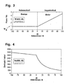
- the series winding 51 no longer generates a magnetic flux, the armature winding 50 is only the constant, caused by the bypass winding 52, a flow (see Fig. 3).
- the speed of the servo motor 5 is thus stabilized (see Fig. 4). Overspeed and thus the risk of instability is counteracted in this way.
- diode is usually already present, namely as part of the rectifier 8, which serves to supply the series closure winding 51 in AC-powered normal operation.
- diode is usually already present, namely as part of the rectifier 8, which serves to supply the series closure winding 51 in AC-powered normal operation.
- additional diodes can of course be provided, for. B. in series with the acting as a freewheeling diode.
- the threshold voltage and thus the current flowing through the series winding 51 current can be influenced.
Landscapes
- Engineering & Computer Science (AREA)
- Power Engineering (AREA)
- Physics & Mathematics (AREA)
- Fluid Mechanics (AREA)
- Life Sciences & Earth Sciences (AREA)
- Sustainable Development (AREA)
- Sustainable Energy (AREA)
- Chemical & Material Sciences (AREA)
- Combustion & Propulsion (AREA)
- Mechanical Engineering (AREA)
- General Engineering & Computer Science (AREA)
- Control Of Eletrric Generators (AREA)
- Wind Motors (AREA)
- Control Of Positive-Displacement Air Blowers (AREA)
- Finger-Pressure Massage (AREA)
- Thermotherapy And Cooling Therapy Devices (AREA)
- Shearing Machines (AREA)
- Eye Examination Apparatus (AREA)
- Manufacture Of Motors, Generators (AREA)
Claims (18)
- Installation éolienne comprenant un rotor (2) avec des pales (3) réglables, un dispositif de réglage (4) pour les pales avec un moteur de commande (5), qui présente un enroulement d'excitation, et un module de commande de pale (6), et un générateur entraîné par le rotor (2), le dispositif de réglage (4) présentant un régime normal et un régime d'urgence, le moteur de commande (5) étant réglé par le module de commande de pale (6) en régime normal et le moteur de commande (5) n'étant pas réglé en régime d'urgence,
caractérisée en ce que
le dispositif de réglage (4) est doté d'un dispositif d'affaiblissement de couple qui est conçu pour réduire automatiquement un couple de traînage du moteur de commande (5) en mode d'urgence par réduction du flux magnétique dans l'enroulement excitateur. - Installation éolienne selon la revendication 1,
caractérisée en ce que
le dispositif d'affaiblissement de couple est conçu pour réduire un courant excitateur (IE) du moteur de commande (5). - Installation éolienne selon la revendication 1 ou 2,
caractérisée en ce que
l'installation d'excitation est réalisée sous la forme d'un enroulement série (51). - Installation éolienne selon l'une quelconque des revendications précédentes,
caractérisée en ce que
un second circuit d'excitation est prévu de préférence sous la forme d'un enroulement shunt (52), sur lequel le dispositif d'affaiblissement de couple n'agit pas. - Installation éolienne selon l'une quelconque des revendications précédentes,
caractérisée en ce que
le dispositif d'affaiblissement est réalisé sous la forme d'un dispositif de roue libre (7), qui shunte l'enroulement d'excitation lorsque le moteur de commande (5) est traîné. - Installation éolienne selon la revendication 5,
caractérisée en ce que
le dispositif de roue libre (7) est réalisé sous la forme d'un relais de courant de repos. - Installation éolienne selon la revendication 5,
caractérisée en ce que
le dispositif de roue libre (7) comprend une diode. - Installation éolienne selon la revendication 5,
caractérisée en ce que
le dispositif de roue libre (7) est réalisé de telle sorte qu'il laisse passer un courant minimum. - Installation éolienne selon l'une quelconque des revendications précédentes,
caractérisée en ce que
le courant d'excitation est guidé au moyen d'un redresseur (8) sur l'enroulement d'excitation, une ligne d'alimentation (9) pour le régime d'urgence au moins avec un pôle étant raccordée côté courant continu du redresseur (8). - Procédé pour modifier l'angle de réglage de pales (3) d'un rotor (2) pour des installations éoliennes avec un moteur de commande (5), qui est réglé en régime normal par un module de commande de pale (6) et est actionné de façon non réglée dans un régime d'urgence, comprenant les étapes suivantes : arrivée d'énergie électrique à un enroulement d'excitation du moteur de commande (5) par une ligne d'alimentation pour le régime d'urgence (9), déplacement des pales (3) dans une position prédéfinie,
caractérisé par
l'actionnement d'un dispositif d'affaiblissement de couple dans le régime d'urgence, qui, en cas de moteur de commande (5) traîné, réduit son couple de traînage par réduction du flux magnétique dans l'enroulement excitateur. - Procédé selon la revendication 10,
caractérisé par
la réduction du courant excitateur (IE) avec le moteur de commande (5) remorqué. - Procédé selon la revendication 11,
caractérisé par
shuntage de l'enroulement d'excitation en régime d'urgence. - Procédé selon l'une quelconque des revendications 10 à 12,
caractérisé par
prévision d'un second enroulement d'excitation qui n'est pas shunté. - Procédé selon l'une quelconque des revendications précédentes,
caractérisé en ce que
un dispositif de roue libre (7) est utilisé comme dispositif d'affaiblissement de couple. - Procédé selon la revendication 14,
caractérisé par
l'utilisation d'un relais de courant de repos comme dispositif de roue libre (7). - Procédé selon la revendication 14,
caractérisé par
l'utilisation d'une diode ou de plusieurs diodes montées en série comme dispositif de roue libre (7). - Procédé selon la revendication 14,
caractérisé par
le passage d'un courant minimum dans le dispositif de roue libre (7). - Procédé selon l'une quelconque des revendications précédentes,
caractérisé en ce que
le guidage du courant excitateur par un redresseur (8) sur l'enroulement excitateur, une ligne d'alimentation (9) pour le régime d'urgence au moins avec un pôle étant guidée côté courant continu par le redresseur (8) sur l'enroulement d'excitation.
Priority Applications (6)
| Application Number | Priority Date | Filing Date | Title |
|---|---|---|---|
| AT05015194T ATE373335T1 (de) | 2005-07-13 | 2005-07-13 | Rotorblattverstellungsvorrichtung |
| EP05015194A EP1744444B1 (fr) | 2005-07-13 | 2005-07-13 | dispositif de réglage du pas pour pale de rotor |
| ES05015194T ES2292017T3 (es) | 2005-07-13 | 2005-07-13 | Dispositivo de regulacion de pala de rotor. |
| DE502005001497T DE502005001497D1 (de) | 2005-07-13 | 2005-07-13 | Rotorblattverstellungsvorrichtung |
| DK05015194T DK1744444T3 (da) | 2005-07-13 | 2005-07-13 | Vingejusteringsanordning |
| PT05015194T PT1744444E (pt) | 2005-07-13 | 2005-07-13 | Dispositivo de orientação das pás de um rotor |
Applications Claiming Priority (1)
| Application Number | Priority Date | Filing Date | Title |
|---|---|---|---|
| EP05015194A EP1744444B1 (fr) | 2005-07-13 | 2005-07-13 | dispositif de réglage du pas pour pale de rotor |
Publications (2)
| Publication Number | Publication Date |
|---|---|
| EP1744444A1 EP1744444A1 (fr) | 2007-01-17 |
| EP1744444B1 true EP1744444B1 (fr) | 2007-09-12 |
Family
ID=35464091
Family Applications (1)
| Application Number | Title | Priority Date | Filing Date |
|---|---|---|---|
| EP05015194A Expired - Lifetime EP1744444B1 (fr) | 2005-07-13 | 2005-07-13 | dispositif de réglage du pas pour pale de rotor |
Country Status (6)
| Country | Link |
|---|---|
| EP (1) | EP1744444B1 (fr) |
| AT (1) | ATE373335T1 (fr) |
| DE (1) | DE502005001497D1 (fr) |
| DK (1) | DK1744444T3 (fr) |
| ES (1) | ES2292017T3 (fr) |
| PT (1) | PT1744444E (fr) |
Families Citing this family (2)
| Publication number | Priority date | Publication date | Assignee | Title |
|---|---|---|---|---|
| DE102007022511B4 (de) | 2007-05-14 | 2009-07-30 | Repower Systems Ag | Windenergieanlage mit einer Verstelleinrichtung für die Rotorblätter |
| DE102019001355A1 (de) | 2019-02-26 | 2020-08-27 | Senvion Gmbh | Rotorblattverstelleinrichtung für Windenergieanlagen |
Family Cites Families (7)
| Publication number | Priority date | Publication date | Assignee | Title |
|---|---|---|---|---|
| GB558914A (en) * | 1942-05-20 | 1944-01-27 | Edward Hollingworth Morris | Improvements in or relating to electric motors |
| US4910443A (en) * | 1989-02-28 | 1990-03-20 | Square D Company | Electronic control circuit for a bidirectional motor |
| DE19644705A1 (de) | 1996-10-28 | 1998-04-30 | Preussag Ag | Vorrichtung zur Verstellung von Rotorblättern |
| DE29722109U1 (de) | 1997-12-16 | 1998-03-26 | aerodyn Engineering GmbH, 24768 Rendsburg | Windenergieanlage |
| DE10009472C2 (de) | 2000-02-28 | 2002-06-13 | Norbert Hennchen | Vorrichtung zum Verstellen der Anstellwinkel der auf einer Nabe einer Rotorwelle verdrehbar angeordneten Rotorblätter einer Windkraftanlage |
| DE20020232U1 (de) | 2000-11-29 | 2002-01-17 | Siemens AG, 80333 München | Windkraftanlage mit Hilfsenergieeinrichtung zur Verstellung von Rotorblättern in einem Fehlerfall |
| DE10253811B4 (de) | 2002-11-18 | 2018-08-23 | Moog Unna Gmbh | Antriebsvorrichtung für eine Windkraftanlage mit elektrisch verstellbaren Flügeln |
-
2005
- 2005-07-13 PT PT05015194T patent/PT1744444E/pt unknown
- 2005-07-13 EP EP05015194A patent/EP1744444B1/fr not_active Expired - Lifetime
- 2005-07-13 AT AT05015194T patent/ATE373335T1/de not_active IP Right Cessation
- 2005-07-13 ES ES05015194T patent/ES2292017T3/es not_active Expired - Lifetime
- 2005-07-13 DE DE502005001497T patent/DE502005001497D1/de not_active Expired - Fee Related
- 2005-07-13 DK DK05015194T patent/DK1744444T3/da active
Also Published As
| Publication number | Publication date |
|---|---|
| PT1744444E (pt) | 2007-11-23 |
| ES2292017T3 (es) | 2008-03-01 |
| DE502005001497D1 (de) | 2007-10-25 |
| DK1744444T3 (da) | 2008-01-02 |
| ATE373335T1 (de) | 2007-09-15 |
| EP1744444A1 (fr) | 2007-01-17 |
Similar Documents
| Publication | Publication Date | Title |
|---|---|---|
| DE102004005169B3 (de) | Rotorblattverstellungsvorrichtung | |
| EP1989440B1 (fr) | Alimentation en énergie pour un dispositif de réglage de pale d'une éolienne | |
| EP2550451B1 (fr) | Dispositif d'entraînement de calage pouvant être utilisé en fonctionnement de secours pour une éolienne ou une installation de centrale hydroélectrique | |
| EP2457320B1 (fr) | Procédé de fonctionnement d'une turbine éolienne et turbine éolienne associée | |
| EP2411669B2 (fr) | Procédé de fonctionnement d'une éolienne | |
| EP2162619B1 (fr) | Dispositif de réglage de pales de rotor d'une éolienne | |
| EP2032845B1 (fr) | Équipement à énergie éolienne muni d'une alimentation à énergie autonome pour un dispositif de positionnement des pales | |
| EP2878808B1 (fr) | Système de pas et procédé de fonctionnement d'un système de pas d'une installation éolienne | |
| WO2005017350A1 (fr) | Installation eolienne munie d'un dispositif de reglage des pales de rotor | |
| EP2058939B1 (fr) | Eolienne dotée d'un commutateur de commande destiné au fonctionnement à vitesse limité et à économie de sources de tension d'un moteur série à collecteur et tangage pour moments de générateur | |
| DE102018008195A1 (de) | Verfahren zum Betreiben einer Windenergieanlage in einem Störfall | |
| EP1379780A1 (fr) | Procede d'utilisation d'une installation a energie eolienne | |
| EP1852605B1 (fr) | Réglage du pas de pales d'une éolienne en cas de situations d'urgence | |
| EP0840949B1 (fr) | Dispositif d'entrainement de convertisseur de puissance | |
| EP1744444B1 (fr) | dispositif de réglage du pas pour pale de rotor | |
| WO2009012776A2 (fr) | Générateur asynchrone à double alimentation et procédé pour le faire fonctionner | |
| DE102007042182A1 (de) | Windenergieanlage sowie Verfahren zum Betreiben einer Windenergieanlage | |
| EP3806261B1 (fr) | Procédé d'alimentation caractérisée par tension d'énergie électrique dans un réseau d'alimentation électrique au moyen d'une éolienne | |
| DE102019001355A1 (de) | Rotorblattverstelleinrichtung für Windenergieanlagen | |
| DE2816126A1 (de) | Verfahren zum starten und umsteuern einer gasturbo-elektrischen antriebsanlage fuer eisbrechende schiffe | |
| DE2855093B2 (de) | Notbremsvorrichtung für einen fremderregten Gleichstrommotor |
Legal Events
| Date | Code | Title | Description |
|---|---|---|---|
| PUAI | Public reference made under article 153(3) epc to a published international application that has entered the european phase |
Free format text: ORIGINAL CODE: 0009012 |
|
| 17P | Request for examination filed |
Effective date: 20060509 |
|
| AK | Designated contracting states |
Kind code of ref document: A1 Designated state(s): AT BE BG CH CY CZ DE DK EE ES FI FR GB GR HU IE IS IT LI LT LU LV MC NL PL PT RO SE SI SK TR |
|
| AX | Request for extension of the european patent |
Extension state: AL BA HR MK YU |
|
| GRAP | Despatch of communication of intention to grant a patent |
Free format text: ORIGINAL CODE: EPIDOSNIGR1 |
|
| GRAS | Grant fee paid |
Free format text: ORIGINAL CODE: EPIDOSNIGR3 |
|
| GRAA | (expected) grant |
Free format text: ORIGINAL CODE: 0009210 |
|
| AK | Designated contracting states |
Kind code of ref document: B1 Designated state(s): AT BE BG CH CY CZ DE DK EE ES FI FR GB GR HU IE IS IT LI LT LU LV MC NL PL PT RO SE SI SK TR |
|
| REG | Reference to a national code |
Ref country code: GB Ref legal event code: FG4D Free format text: NOT ENGLISH |
|
| AKX | Designation fees paid |
Designated state(s): AT BE BG CH CY CZ DE DK EE ES FI FR GB GR HU IE IS IT LI LT LU LV MC NL PL PT RO SE SI SK TR |
|
| REG | Reference to a national code |
Ref country code: CH Ref legal event code: EP |
|
| REF | Corresponds to: |
Ref document number: 502005001497 Country of ref document: DE Date of ref document: 20071025 Kind code of ref document: P |
|
| REG | Reference to a national code |
Ref country code: IE Ref legal event code: FG4D Free format text: LANGUAGE OF EP DOCUMENT: GERMAN |
|
| REG | Reference to a national code |
Ref country code: PT Ref legal event code: SC4A Free format text: AVAILABILITY OF NATIONAL TRANSLATION Effective date: 20071112 |
|
| REG | Reference to a national code |
Ref country code: DK Ref legal event code: T3 |
|
| GBT | Gb: translation of ep patent filed (gb section 77(6)(a)/1977) | ||
| PG25 | Lapsed in a contracting state [announced via postgrant information from national office to epo] |
Ref country code: LT Free format text: LAPSE BECAUSE OF FAILURE TO SUBMIT A TRANSLATION OF THE DESCRIPTION OR TO PAY THE FEE WITHIN THE PRESCRIBED TIME-LIMIT Effective date: 20070912 Ref country code: FI Free format text: LAPSE BECAUSE OF FAILURE TO SUBMIT A TRANSLATION OF THE DESCRIPTION OR TO PAY THE FEE WITHIN THE PRESCRIBED TIME-LIMIT Effective date: 20070912 |
|
| PG25 | Lapsed in a contracting state [announced via postgrant information from national office to epo] |
Ref country code: PL Free format text: LAPSE BECAUSE OF FAILURE TO SUBMIT A TRANSLATION OF THE DESCRIPTION OR TO PAY THE FEE WITHIN THE PRESCRIBED TIME-LIMIT Effective date: 20070912 |
|
| REG | Reference to a national code |
Ref country code: ES Ref legal event code: FG2A Ref document number: 2292017 Country of ref document: ES Kind code of ref document: T3 |
|
| NLV1 | Nl: lapsed or annulled due to failure to fulfill the requirements of art. 29p and 29m of the patents act | ||
| PG25 | Lapsed in a contracting state [announced via postgrant information from national office to epo] |
Ref country code: LV Free format text: LAPSE BECAUSE OF FAILURE TO SUBMIT A TRANSLATION OF THE DESCRIPTION OR TO PAY THE FEE WITHIN THE PRESCRIBED TIME-LIMIT Effective date: 20070912 |
|
| ET | Fr: translation filed | ||
| PG25 | Lapsed in a contracting state [announced via postgrant information from national office to epo] |
Ref country code: GR Free format text: LAPSE BECAUSE OF FAILURE TO SUBMIT A TRANSLATION OF THE DESCRIPTION OR TO PAY THE FEE WITHIN THE PRESCRIBED TIME-LIMIT Effective date: 20071213 Ref country code: NL Free format text: LAPSE BECAUSE OF FAILURE TO SUBMIT A TRANSLATION OF THE DESCRIPTION OR TO PAY THE FEE WITHIN THE PRESCRIBED TIME-LIMIT Effective date: 20070912 |
|
| REG | Reference to a national code |
Ref country code: IE Ref legal event code: FD4D |
|
| PG25 | Lapsed in a contracting state [announced via postgrant information from national office to epo] |
Ref country code: SK Free format text: LAPSE BECAUSE OF FAILURE TO SUBMIT A TRANSLATION OF THE DESCRIPTION OR TO PAY THE FEE WITHIN THE PRESCRIBED TIME-LIMIT Effective date: 20070912 Ref country code: CZ Free format text: LAPSE BECAUSE OF FAILURE TO SUBMIT A TRANSLATION OF THE DESCRIPTION OR TO PAY THE FEE WITHIN THE PRESCRIBED TIME-LIMIT Effective date: 20070912 Ref country code: IS Free format text: LAPSE BECAUSE OF FAILURE TO SUBMIT A TRANSLATION OF THE DESCRIPTION OR TO PAY THE FEE WITHIN THE PRESCRIBED TIME-LIMIT Effective date: 20080112 |
|
| PG25 | Lapsed in a contracting state [announced via postgrant information from national office to epo] |
Ref country code: RO Free format text: LAPSE BECAUSE OF FAILURE TO SUBMIT A TRANSLATION OF THE DESCRIPTION OR TO PAY THE FEE WITHIN THE PRESCRIBED TIME-LIMIT Effective date: 20070912 Ref country code: SE Free format text: LAPSE BECAUSE OF FAILURE TO SUBMIT A TRANSLATION OF THE DESCRIPTION OR TO PAY THE FEE WITHIN THE PRESCRIBED TIME-LIMIT Effective date: 20071212 |
|
| PLBE | No opposition filed within time limit |
Free format text: ORIGINAL CODE: 0009261 |
|
| STAA | Information on the status of an ep patent application or granted ep patent |
Free format text: STATUS: NO OPPOSITION FILED WITHIN TIME LIMIT |
|
| 26N | No opposition filed |
Effective date: 20080613 |
|
| PG25 | Lapsed in a contracting state [announced via postgrant information from national office to epo] |
Ref country code: IE Free format text: LAPSE BECAUSE OF FAILURE TO SUBMIT A TRANSLATION OF THE DESCRIPTION OR TO PAY THE FEE WITHIN THE PRESCRIBED TIME-LIMIT Effective date: 20070912 |
|
| PG25 | Lapsed in a contracting state [announced via postgrant information from national office to epo] |
Ref country code: MC Free format text: LAPSE BECAUSE OF NON-PAYMENT OF DUE FEES Effective date: 20080731 |
|
| PG25 | Lapsed in a contracting state [announced via postgrant information from national office to epo] |
Ref country code: EE Free format text: LAPSE BECAUSE OF FAILURE TO SUBMIT A TRANSLATION OF THE DESCRIPTION OR TO PAY THE FEE WITHIN THE PRESCRIBED TIME-LIMIT Effective date: 20070912 Ref country code: DE Free format text: LAPSE BECAUSE OF NON-PAYMENT OF DUE FEES Effective date: 20090203 |
|
| PG25 | Lapsed in a contracting state [announced via postgrant information from national office to epo] |
Ref country code: SI Free format text: LAPSE BECAUSE OF FAILURE TO SUBMIT A TRANSLATION OF THE DESCRIPTION OR TO PAY THE FEE WITHIN THE PRESCRIBED TIME-LIMIT Effective date: 20070912 |
|
| PG25 | Lapsed in a contracting state [announced via postgrant information from national office to epo] |
Ref country code: CY Free format text: LAPSE BECAUSE OF FAILURE TO SUBMIT A TRANSLATION OF THE DESCRIPTION OR TO PAY THE FEE WITHIN THE PRESCRIBED TIME-LIMIT Effective date: 20070912 |
|
| PG25 | Lapsed in a contracting state [announced via postgrant information from national office to epo] |
Ref country code: BG Free format text: LAPSE BECAUSE OF FAILURE TO SUBMIT A TRANSLATION OF THE DESCRIPTION OR TO PAY THE FEE WITHIN THE PRESCRIBED TIME-LIMIT Effective date: 20071212 |
|
| PG25 | Lapsed in a contracting state [announced via postgrant information from national office to epo] |
Ref country code: AT Free format text: LAPSE BECAUSE OF NON-PAYMENT OF DUE FEES Effective date: 20080713 |
|
| REG | Reference to a national code |
Ref country code: CH Ref legal event code: PL |
|
| PG25 | Lapsed in a contracting state [announced via postgrant information from national office to epo] |
Ref country code: CH Free format text: LAPSE BECAUSE OF NON-PAYMENT OF DUE FEES Effective date: 20090731 Ref country code: LI Free format text: LAPSE BECAUSE OF NON-PAYMENT OF DUE FEES Effective date: 20090731 |
|
| PG25 | Lapsed in a contracting state [announced via postgrant information from national office to epo] |
Ref country code: LU Free format text: LAPSE BECAUSE OF NON-PAYMENT OF DUE FEES Effective date: 20080713 Ref country code: HU Free format text: LAPSE BECAUSE OF FAILURE TO SUBMIT A TRANSLATION OF THE DESCRIPTION OR TO PAY THE FEE WITHIN THE PRESCRIBED TIME-LIMIT Effective date: 20080313 Ref country code: BE Free format text: LAPSE BECAUSE OF NON-PAYMENT OF DUE FEES Effective date: 20080731 |
|
| PG25 | Lapsed in a contracting state [announced via postgrant information from national office to epo] |
Ref country code: TR Free format text: LAPSE BECAUSE OF FAILURE TO SUBMIT A TRANSLATION OF THE DESCRIPTION OR TO PAY THE FEE WITHIN THE PRESCRIBED TIME-LIMIT Effective date: 20070912 |
|
| REG | Reference to a national code |
Ref country code: ES Ref legal event code: PC2A Owner name: SENVION SE Effective date: 20150127 |
|
| REG | Reference to a national code |
Ref country code: FR Ref legal event code: CA Effective date: 20150330 Ref country code: FR Ref legal event code: CD Owner name: SENVION SE, DE Effective date: 20150330 |
|
| REG | Reference to a national code |
Ref country code: FR Ref legal event code: PLFP Year of fee payment: 12 |
|
| REG | Reference to a national code |
Ref country code: FR Ref legal event code: PLFP Year of fee payment: 13 |
|
| REG | Reference to a national code |
Ref country code: FR Ref legal event code: PLFP Year of fee payment: 14 |
|
| PGFP | Annual fee paid to national office [announced via postgrant information from national office to epo] |
Ref country code: GB Payment date: 20200724 Year of fee payment: 16 Ref country code: DK Payment date: 20200722 Year of fee payment: 16 Ref country code: PT Payment date: 20200706 Year of fee payment: 16 Ref country code: FR Payment date: 20200727 Year of fee payment: 16 Ref country code: ES Payment date: 20200818 Year of fee payment: 16 |
|
| PGFP | Annual fee paid to national office [announced via postgrant information from national office to epo] |
Ref country code: IT Payment date: 20200731 Year of fee payment: 16 |
|
| REG | Reference to a national code |
Ref country code: DK Ref legal event code: EBP Effective date: 20210731 |
|
| GBPC | Gb: european patent ceased through non-payment of renewal fee |
Effective date: 20210713 |
|
| PG25 | Lapsed in a contracting state [announced via postgrant information from national office to epo] |
Ref country code: GB Free format text: LAPSE BECAUSE OF NON-PAYMENT OF DUE FEES Effective date: 20210713 |
|
| PG25 | Lapsed in a contracting state [announced via postgrant information from national office to epo] |
Ref country code: PT Free format text: LAPSE BECAUSE OF NON-PAYMENT OF DUE FEES Effective date: 20220113 Ref country code: FR Free format text: LAPSE BECAUSE OF NON-PAYMENT OF DUE FEES Effective date: 20210731 |
|
| PG25 | Lapsed in a contracting state [announced via postgrant information from national office to epo] |
Ref country code: IT Free format text: LAPSE BECAUSE OF NON-PAYMENT OF DUE FEES Effective date: 20210713 Ref country code: DK Free format text: LAPSE BECAUSE OF NON-PAYMENT OF DUE FEES Effective date: 20210731 |
|
| REG | Reference to a national code |
Ref country code: ES Ref legal event code: FD2A Effective date: 20220830 |
|
| PG25 | Lapsed in a contracting state [announced via postgrant information from national office to epo] |
Ref country code: ES Free format text: LAPSE BECAUSE OF NON-PAYMENT OF DUE FEES Effective date: 20210714 |