EP1744845B1 - Werkzeug für eine maschine zum abheben von spänen mit verstellbarem spitzsenker - Google Patents
Werkzeug für eine maschine zum abheben von spänen mit verstellbarem spitzsenker Download PDFInfo
- Publication number
- EP1744845B1 EP1744845B1 EP04749068A EP04749068A EP1744845B1 EP 1744845 B1 EP1744845 B1 EP 1744845B1 EP 04749068 A EP04749068 A EP 04749068A EP 04749068 A EP04749068 A EP 04749068A EP 1744845 B1 EP1744845 B1 EP 1744845B1
- Authority
- EP
- European Patent Office
- Prior art keywords
- countersink
- drill
- tool
- insert
- pin
- Prior art date
- Legal status (The legal status is an assumption and is not a legal conclusion. Google has not performed a legal analysis and makes no representation as to the accuracy of the status listed.)
- Expired - Lifetime
Links
- 238000003754 machining Methods 0.000 title claims abstract description 8
- 238000006073 displacement reaction Methods 0.000 claims abstract description 6
- 230000004913 activation Effects 0.000 claims abstract 2
- 238000004873 anchoring Methods 0.000 claims description 19
- 238000005553 drilling Methods 0.000 description 3
- 230000006978 adaptation Effects 0.000 description 1
- 238000005452 bending Methods 0.000 description 1
- 230000001419 dependent effect Effects 0.000 description 1
- 238000000034 method Methods 0.000 description 1
- 238000012986 modification Methods 0.000 description 1
- 230000004048 modification Effects 0.000 description 1
- 238000007493 shaping process Methods 0.000 description 1
Images


Classifications
-
- B—PERFORMING OPERATIONS; TRANSPORTING
- B23—MACHINE TOOLS; METAL-WORKING NOT OTHERWISE PROVIDED FOR
- B23B—TURNING; BORING
- B23B51/00—Tools for drilling machines
- B23B51/10—Bits for countersinking
-
- B—PERFORMING OPERATIONS; TRANSPORTING
- B23—MACHINE TOOLS; METAL-WORKING NOT OTHERWISE PROVIDED FOR
- B23B—TURNING; BORING
- B23B51/00—Tools for drilling machines
- B23B51/10—Bits for countersinking
- B23B51/108—Bits for countersinking having a centering drill
-
- B—PERFORMING OPERATIONS; TRANSPORTING
- B23—MACHINE TOOLS; METAL-WORKING NOT OTHERWISE PROVIDED FOR
- B23B—TURNING; BORING
- B23B27/00—Tools for turning or boring machines; Tools of a similar kind in general; Accessories therefor
- B23B27/14—Cutting tools of which the bits or tips or cutting inserts are of special material
- B23B27/141—Specially shaped plate-like cutting inserts, i.e. length greater or equal to width, width greater than or equal to thickness
-
- B—PERFORMING OPERATIONS; TRANSPORTING
- B23—MACHINE TOOLS; METAL-WORKING NOT OTHERWISE PROVIDED FOR
- B23B—TURNING; BORING
- B23B2200/00—Details of cutting inserts
- B23B2200/08—Rake or top surfaces
- B23B2200/086—Rake or top surfaces with one or more grooves
- B23B2200/087—Rake or top surfaces with one or more grooves for chip breaking
-
- B—PERFORMING OPERATIONS; TRANSPORTING
- B23—MACHINE TOOLS; METAL-WORKING NOT OTHERWISE PROVIDED FOR
- B23B—TURNING; BORING
- B23B2200/00—Details of cutting inserts
- B23B2200/16—Supporting or bottom surfaces
- B23B2200/167—Supporting or bottom surfaces with serrations
-
- B—PERFORMING OPERATIONS; TRANSPORTING
- B23—MACHINE TOOLS; METAL-WORKING NOT OTHERWISE PROVIDED FOR
- B23B—TURNING; BORING
- B23B2260/00—Details of constructional elements
- B23B2260/004—Adjustable elements
-
- Y—GENERAL TAGGING OF NEW TECHNOLOGICAL DEVELOPMENTS; GENERAL TAGGING OF CROSS-SECTIONAL TECHNOLOGIES SPANNING OVER SEVERAL SECTIONS OF THE IPC; TECHNICAL SUBJECTS COVERED BY FORMER USPC CROSS-REFERENCE ART COLLECTIONS [XRACs] AND DIGESTS
- Y10—TECHNICAL SUBJECTS COVERED BY FORMER USPC
- Y10T—TECHNICAL SUBJECTS COVERED BY FORMER US CLASSIFICATION
- Y10T408/00—Cutting by use of rotating axially moving tool
- Y10T408/60—Plural tool-assemblages
- Y10T408/62—Coaxial
-
- Y—GENERAL TAGGING OF NEW TECHNOLOGICAL DEVELOPMENTS; GENERAL TAGGING OF CROSS-SECTIONAL TECHNOLOGIES SPANNING OVER SEVERAL SECTIONS OF THE IPC; TECHNICAL SUBJECTS COVERED BY FORMER USPC CROSS-REFERENCE ART COLLECTIONS [XRACs] AND DIGESTS
- Y10—TECHNICAL SUBJECTS COVERED BY FORMER USPC
- Y10T—TECHNICAL SUBJECTS COVERED BY FORMER US CLASSIFICATION
- Y10T408/00—Cutting by use of rotating axially moving tool
- Y10T408/83—Tool-support with means to move Tool relative to tool-support
- Y10T408/85—Tool-support with means to move Tool relative to tool-support to move radially
- Y10T408/858—Moving means including wedge, screw or cam
- Y10T408/8598—Screw extending perpendicular to tool-axis
-
- Y—GENERAL TAGGING OF NEW TECHNOLOGICAL DEVELOPMENTS; GENERAL TAGGING OF CROSS-SECTIONAL TECHNOLOGIES SPANNING OVER SEVERAL SECTIONS OF THE IPC; TECHNICAL SUBJECTS COVERED BY FORMER USPC CROSS-REFERENCE ART COLLECTIONS [XRACs] AND DIGESTS
- Y10—TECHNICAL SUBJECTS COVERED BY FORMER USPC
- Y10T—TECHNICAL SUBJECTS COVERED BY FORMER US CLASSIFICATION
- Y10T408/00—Cutting by use of rotating axially moving tool
- Y10T408/86—Tool-support with means to permit positioning of the Tool relative to support
- Y10T408/87—Tool having stepped cutting edges
- Y10T408/8725—Tool having stepped cutting edges including means to permit relative axial positioning of edges
-
- Y—GENERAL TAGGING OF NEW TECHNOLOGICAL DEVELOPMENTS; GENERAL TAGGING OF CROSS-SECTIONAL TECHNOLOGIES SPANNING OVER SEVERAL SECTIONS OF THE IPC; TECHNICAL SUBJECTS COVERED BY FORMER USPC CROSS-REFERENCE ART COLLECTIONS [XRACs] AND DIGESTS
- Y10—TECHNICAL SUBJECTS COVERED BY FORMER USPC
- Y10T—TECHNICAL SUBJECTS COVERED BY FORMER US CLASSIFICATION
- Y10T408/00—Cutting by use of rotating axially moving tool
- Y10T408/89—Tool or Tool with support
- Y10T408/905—Having stepped cutting edges
- Y10T408/906—Axially spaced
Definitions
- the present invention relates to a countersink for chip removing machining, according to the appended independent claims.
- US-A-5,915,895 is previously known a tool for drilling and chamfering, wherein the tool comprises a base body, in which a drill is received. At the end of the base body situated closest to the drill tip means are provided in order to achieve chamfering. These means are made of specially designed cutting inserts that are fixed on the base body via a screw and clamp combination.
- the tool according to US-A-5,915,895 does not show any arrangement for precisely adjusting the positions of the cutting inserts.
- US-A-5,265,988 is previously known a tool for drilling and chamfering, wherein the tool comprises a tool holder having a chamfering head at its forward end, where two cutting blades are held, diagonally opposite to each other.
- a drill with a shank portion is received in the tool holder.
- the cutting blades are held by screw and clamp combination.
- the cutting blades are received in grooves that form a certain angle with the axis of rotation of the tool, wherein the cutting blades are adjustable in grooves in connection with that it is mounted on the chamfering head.
- the tool according to US-A-5,265,988 does not show any arrangement for precisely adjusting the positions of the cutting blades.
- WO 95/07787 shows a tool for chip removing machining.
- the known tool comprises cutting inserts that are intended to perform an additional machining operation, for example chamfering or countersinking,
- the tool has means for adjusting the positions of the cutting insert. These means comprise a slide with a oblong hole, carrying a cutting insert. The slide can be displaced relative to a locking screw, which fixes the slide in position. The displacement of the slide occurs wholly manually.
- a primary object of the present invention is to provide a countersink of the above-captioned type, which countersink enables a precise adjustment of the cutting inserts forming a parts of the countersink to the actual operative diameter of the standard drill.
- Another object of the present invention is to simplify the mounting of the countersink on the drill
- Still another object of the present invention is to achieve an infinitely variable adjustment of the cutting inserts producing the chamfer.
- Still another object of the present invention is to achieve an infinitely variable adjustment of the drill depth.
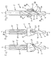
- the tool shown in Figs. 1-3 comprises a countersink 1, which is mounted on a drill 3, which may be of standard configuration.
- the drill 3 is a helix drill, which has at least one protruding land 4 and a chip flute 6.
- the countersink 1, forming a part of the tool, according to the present invention is shown in Figs. 1-3 and in Figs. 4 and 5 .
- the countersink 1 comprises an anchoring portion 5 and an insert-receiving portion 7, wherein the anchoring portion 5 is provided with a male thread 9 while the insert-receiving portion 7 is provided with a female thread 10.
- the male thread 9 and the female thread 10 can be brought into engagement with each other during forming of a thread joint.
- a collar 11 is provided in connection with the male thread 9, wherein this collar 11 will get into abutment against an end surface 12 of the insert-receiving portion 7. Thereby, a connection is achieved between the anchoring portion 5 and the insert-receiving portion 7, which can receive relatively large bending stresses.
- the anchoring portion 5 is generally designed as a sleeve, which is intended to be placed over a shank portion 13, see Fig. 3 , of the drill 3 that also comprises a hole-making portion 14.
- the anchoring portion 5 is provided with slots 15 that alternately opens into the free end of the anchoring portions 5 and extend forwardly to the collar 11, respectively.
- the provision of slots 15 makes that the anchoring portion 5 becomes somewhat flexible, which facilitates attachment of the anchoring portion 5 on the shank portion 13 of the drill 3.
- the insert-receiving portion 7 comprises two insert pockets 20 for a cutting insert for chip removing machining, two cutting insert 21 provided in these insert pockets, first means 22 for clamping the cutting inserts 21 in the insert pockets 20 and second means 23 for adjusting the positions of the cutting inserts 21 in their respective insert pockets 20.
- the insert pockets 20 are placed diametrically opposed with regard to the axis C-C of rotation of the tool.
- the insert pockets 20 are provided with first serrations 24 and the lower side of the cutting inserts 21 are provided with second serrations 25, wherein the first serrations 24 and the second serrations 25 come into engagement with each other when a cutting insert 21 is placed in its associated cutting insert pocket 20.
- the longitudinal direction of the first serrations 24 that coincides with the cross-sectional line VI-VI in Fig. 3 , slopes a certain angle ⁇ relative to the axis C-C of rotation of the tool.
- the first means for clamping a cutting insert 21 in its associated cutting insert pocket 20 is according to the shown embodiment made of a center screw 22, which is received by a center hole 26 of the cutting Insert 21.
- Each insert pocket 20 is also provided with a through-going first hole 27, through which the center screw 22 passes when it is in active position.
- Second means 23 for adjusting of the cutting insert 21 position in its respective insert pocket 20 is provided in connection with each insert pocket 20.
- Each second means 23 in the shown embodiment comprises two second and third holes 28 and 29 arranged beside each other in the insert-receiving portion 7.
- the holes 28 and 29 are provided in immediate connection with its associated insert pocket 20 and each having an extension longitudinally along the longitudinal direction of the first serrations 24.
- the second hole 28 is not threaded while the third hole 29 is threaded.
- Fig. 6 it is visible that the second hole 28, in which a pin 30 or a displaceable member is received, said pin 30 having a threaded, through-going fourth hole 31 extending laterally to the longitudinal direction of the pin 30.
- the mutual dimensions of the second hole 28 and the pin 30 are such that the pin 30 is displaceable in the second hole 28, i.e. slide fit is present between the second hole 28 and the pin 30.
- the fourth hole 31 is intended to cooperate with the center screw 22, i.e. the center screw 22 can be threaded into the fourth hole 31.
- An adjustment screw or adjustment member 32 which likewise forms a part of the means for adjusting the cutting insert 21 positions in their respective insert pockets 20, is received in the third hole 29 and cooperates with a surface of the pin 30 that is generally lateral to the longitudinal direction of the in 30.
- a cutting insert 21 When a cutting insert 21 shall be fixed in its associated cutting insert pocket 20, see Figs. 6 and 7 , the cutting insert 21 is placed in the insert pocket 20, whereby the first and second serrations 24, 25 are brought into engagement with each other.
- the center screw 22 is received in the center hole 26 of the cutting insert 21, whereafter it extends through the first hole 27 in the insert pocket 20 and forms a thread joint with the fourth hole 31 in the pin 30, which is arranged in the second hole 28.
- the adjustment screw 32 is placed in the third hole 29, whereby the adjustment screw 32 is brought to abutment against the lateral surface of the pin 30. Initially a complete tightening of the center screw 22 is not performed, which enables the pin 30 to be displaced by the adjustment screw 32 being rotated in its threaded third hole 29.
- the tool comprises the above-described countersink 1 and the drill 3, on which the countersink 1 is mounted.
- the anchoring portion 5 of the countersink 1 is provided on the shank portion 13 of the drill 3, wherein the shaping of the anchoring portion 5 as a slotted sleeve makes that the countersink 1 easily can be mounted on the drill 3 and be displaced in the longitudinal direction of the drill 3.
- the nose of the cutting insert 21 facing towards of the drill 3 tip is situated in the area of the protruding land 4 of the drill 3, i.e. one nose 34 of the cutting insert 21 abuts against the protruding land 4 of the drill 3, which thus constitutes a stop abutment for the cutting insert 21.
- the cutting insert 21 is provided with a chamfer 35 in the area of the cutting insert 21 intended to abut against the protruding land 4 of the drill 3.
- the chamfer 35 has an axial dimension that is substantially parallel with the axial extension of the protruding land 4.
- the abutments of the cutting inserts 21 against the drill 3 contribute to some degree to the stability of the free end of the drill.
- the anchoring portion 5 can be displaced in axial direction relative to the drill 3 by having a flexible anchorage on the shank portion 13 of the anchoring portion 5, whereby the drill depth easily can be varied. At this displacement the nose 34 of the cutting insert 21 facing towards the drill 3 tip is positioned in connection to a protruding land 4 of the drill 3. At use of the tool both the anchoring portion 5 and the internally located shank portion 13 are provided in a chuck or similar. The slots 15 of the anchoring portion 5 thereby bring about that the anchoring portion 5 and the shank portion 13 will become rigid in the rotational direction relative to each other.
- the countersink 1 is mounted on a helix drill 3, which seems be the most preferred combination.
- the countersink 1 may be mounted on another type of drill.
- center screws 22 clamp the cutting inserts 21.
- the cutting inserts are clamped by an alternative method, wherein in exemplifying and but not limiting purpose top clamps can be mentioned.
Landscapes
- Engineering & Computer Science (AREA)
- Mechanical Engineering (AREA)
- Drilling Tools (AREA)
Claims (3)
- Senkwerkzeug (1), welches für die Montage an einem Schaftabschnitt (13) eines Bohrers (3) vorgesehen ist, wobei das Senkwerkzeug (1) mit zumindest zwei Schneideinsätzen (21) für die spanabhebende Bearbeitung versehen ist, und erste Einrichtungen (2) zum Befestigen der Schneideinsätze (21) in ihren entsprechenden Einsatztaschen (20) hat, wobei das Senkwerkzeug (1) getrennte zweite Einrichtungen (23) zum Einstellen der Position der Schneideinsätze (21) relativ zu dem Bohrer (3) hat, wobei die getrennten zweiten Einstelleinrichtungen (23), die zu einem Schneideinsatz (21) gehören, ein Element (30) aufweisen, welches relativ zu der zugehörigen Einsatztasche (20) verschiebbar ist, sowie ein Einstellelement (32) aufweisen, um eine Verschiebung auf das Element (30) zu übertragen, wobei das verschiebbare Element (30) so ausgestaltet ist, dass es in einen kraftübertragenden Eingriff mit der zweiten Einrichtung (22) zum Befestigen des Schneideinsatzes (21) gebracht wird, dadurch gekennzeichnet, dass das verschiebbare Element aus einem Stift (30) besteht, der in einer Bohrung (23) in dem Senkwerkzeug (1) aufgenommen ist, dass das Einstellelement aus einer Einstellschraube (32) besteht, die in einer Gewindebohrung (29) in dem Senkwerkzeug (1) aufgenommen ist, und dass der Stift (30) und die Einstellschraube (32) relativ zueinander so angeordnet sind, dass beim Betätigen der Einstellschraube (32) der Stift (30) eine Verschiebung erfährt.
- Senkwerkzeug (1) nach Anspruch 1, dadurch gekennzeichnet, dass die Einrichtungen zum Befestigen des Schneideinsatzes (21) aus einer zentralen Schraube (22) bestehen und dass das verschiebbare Element (30) eine Gewindebohrung (31) hat, die für das Aufnehmen der zentralen Schraube (22) vorgesehen ist.
- Senkwerkzeug (1) nach Anspruch 1 oder 2, dadurch gekennzeichnet, dass das Senkwerkzeug (1) einen Verankerungsabschnitt in Form einer Hülse (5) hat, die mit axialen Schlitzen (15) versehen ist, und dass der Verankerungsabschnitt dafür vorgesehen ist, auf einem Schaftabschnitt (13) des Bohrers (3) aufgenommen zu werden.
Applications Claiming Priority (2)
| Application Number | Priority Date | Filing Date | Title |
|---|---|---|---|
| SE0301962A SE526506C2 (sv) | 2003-07-03 | 2003-07-03 | Verktyg för spånavskiljande bearbetning försett med en försänkare med ett förskjutbart element |
| PCT/SE2004/001030 WO2005002767A1 (en) | 2003-07-03 | 2004-06-24 | Tool for chip removing machining with adjustable countersink |
Publications (2)
| Publication Number | Publication Date |
|---|---|
| EP1744845A1 EP1744845A1 (de) | 2007-01-24 |
| EP1744845B1 true EP1744845B1 (de) | 2012-06-13 |
Family
ID=27731088
Family Applications (1)
| Application Number | Title | Priority Date | Filing Date |
|---|---|---|---|
| EP04749068A Expired - Lifetime EP1744845B1 (de) | 2003-07-03 | 2004-06-24 | Werkzeug für eine maschine zum abheben von spänen mit verstellbarem spitzsenker |
Country Status (7)
| Country | Link |
|---|---|
| US (1) | US7131798B2 (de) |
| EP (1) | EP1744845B1 (de) |
| KR (1) | KR101202223B1 (de) |
| CN (1) | CN100393460C (de) |
| CZ (1) | CZ301640B6 (de) |
| SE (1) | SE526506C2 (de) |
| WO (1) | WO2005002767A1 (de) |
Families Citing this family (22)
| Publication number | Priority date | Publication date | Assignee | Title |
|---|---|---|---|---|
| DE10159512A1 (de) * | 2001-12-04 | 2003-06-12 | Kennametal Inc | Zerspanungswerkzeug |
| US20060120814A1 (en) * | 2004-12-02 | 2006-06-08 | Lipohar Steve P | Combination tool |
| DE102006060664A1 (de) * | 2006-12-21 | 2008-06-26 | Kennametal Inc. | Schneideinsatz, insbesondere für Aufbohr- und/oder Senkoperationen |
| RU2374043C2 (ru) * | 2007-10-22 | 2009-11-27 | Лев Николаевич Бурков | Комбинированный инструмент и способ выполнения отверстия под винт с потайной головкой с его использованием |
| US8469642B1 (en) | 2009-03-19 | 2013-06-25 | Precorp, Inc. | Modular precision drill countersink assembly |
| ITMO20130055A1 (it) * | 2013-03-01 | 2014-09-02 | Sau S P A | Gruppo portautensili perfezionato per l'esecuzione simultanea di una foratura e di almeno una ulteriore lavorazione rotativa coassiale. |
| CN103658773A (zh) * | 2013-12-15 | 2014-03-26 | 苏州蓝王机床工具科技有限公司 | 高速倒角刀具 |
| DE102014115768B3 (de) * | 2014-08-12 | 2016-01-21 | Gühring KG | Anschlag für ein Bohr-, Fräs- oder Senkwerkzeug |
| CN104227093B (zh) * | 2014-09-12 | 2017-01-25 | 广西玉林达业机械配件有限公司 | 钻尖定心锪刀 |
| KR101655872B1 (ko) * | 2015-01-08 | 2016-09-08 | 채종구 | 드릴장치용 콜렉척 |
| CN104801767B (zh) * | 2015-03-30 | 2017-03-15 | 温州任和教育科技有限责任公司 | 一种收紧式双头夹紧倒角器 |
| CN104801768A (zh) * | 2015-03-30 | 2015-07-29 | 苏州蓝王机床工具科技有限公司 | 双头锥台旋压锁紧式倒角器 |
| CN104801777A (zh) * | 2015-03-30 | 2015-07-29 | 苏州蓝王机床工具科技有限公司 | 一种卡入刀槽式简易倒角器 |
| CN104801774B (zh) * | 2015-03-30 | 2017-04-05 | 温州任和教育科技有限责任公司 | 一种扳卡弹性套锁紧式倒角器 |
| DE102017210986B4 (de) * | 2017-06-28 | 2024-01-18 | Kennametal Inc. | Reduzierhülse |
| US10974307B2 (en) * | 2017-12-15 | 2021-04-13 | General Electric Technology Gmbh | System, method and apparatus for manipulating a workpiece |
| DE102019203531B4 (de) * | 2019-03-15 | 2023-06-22 | Kennametal Inc. | Kombinationswerkzeug sowie Bohrer für ein derartiges Bohr-/Faswerkzeug |
| EP3888826A1 (de) | 2020-03-31 | 2021-10-06 | CERATIZIT Austria Gesellschaft m.b.H. | Zerspanungswerkzeug und verfahren zum indexieren eines schneideinsatzes |
| US20240024968A1 (en) * | 2022-07-21 | 2024-01-25 | Ab Sandvik Coromant | Thermoset body countersink |
| GB2628417A (en) * | 2023-03-24 | 2024-09-25 | Exactaform Cutting Tools Ltd | Combination tool |
| DE102023120367B4 (de) | 2023-08-01 | 2025-10-02 | Audi Aktiengesellschaft | Bohrsenkwerkzeug-Anordnung |
| DE102023120368B3 (de) | 2023-08-01 | 2024-09-19 | Audi Aktiengesellschaft | Bohrsenkwerkzeug-Anordnung |
Family Cites Families (29)
| Publication number | Priority date | Publication date | Assignee | Title |
|---|---|---|---|---|
| FR598473A (fr) | 1925-05-15 | 1925-12-17 | Packet Et Ses Fils J | Dispositif d'outil permettant de percer et fraiser successivement en une seule opération |
| US2042081A (en) | 1935-09-13 | 1936-05-26 | Kelly Reamer Company | Inserted blade type cutter |
| SE347673B (de) | 1969-11-24 | 1972-08-14 | Sandvikens Jernverks Ab | |
| US3794438A (en) * | 1972-02-10 | 1974-02-26 | A Knutsson | Countersink assembly |
| US4171656A (en) | 1977-08-15 | 1979-10-23 | Gargrave Robert J | Tools and dies facilitating accurate positioning of tools and their connection to retainers |
| US4197042A (en) | 1977-12-15 | 1980-04-08 | Everede Tool Company | Countersinking tool |
| US4353670A (en) | 1980-06-02 | 1982-10-12 | Everede Tool Company | Machining tool |
| DE3125480A1 (de) * | 1981-06-29 | 1983-01-13 | Stadtwerke Neu-Isenburg, 6078 Neu-Isenburg | Bohrvorrichtung, insbesondere fuer das herstellen radialer abzweigbohrungen an roehren aus stahl, gusseisen, keramik etc. |
| DE3201508C1 (de) | 1982-01-20 | 1988-07-07 | Mapal Fabrik für Präzisionswerkzeuge Dr.Kress KG, 7080 Aalen | Einmesser-Reibahle |
| CH650431A5 (fr) | 1983-02-09 | 1985-07-31 | Samvaz Sa | Outil de coupe a couteaux amovibles. |
| US4533285A (en) * | 1983-06-09 | 1985-08-06 | Everede Tool Company | Cutting attachment for boring tool |
| DE3343448A1 (de) | 1983-12-01 | 1985-06-13 | Hochmuth + Hollfelder, 8500 Nürnberg | Schneidwerkzeug zur spanabhebenden metallbearbeitung |
| WO1987000100A1 (en) * | 1985-07-01 | 1987-01-15 | Caterpillar Inc. | Adjustable length chamfering tool |
| US4693641A (en) | 1985-10-25 | 1987-09-15 | Mitsubishi Kinzoku Kabushiki Kaisha | End mill with throw-away tip |
| DE3610016A1 (de) * | 1986-03-25 | 1987-10-01 | Guenther Dr Hartner | Stufenbohrer |
| SE453532B (sv) | 1986-06-03 | 1988-02-08 | Sandvik Ab | Borr med medel for utforande av en sekunder funktion |
| DE8814843U1 (de) * | 1988-10-17 | 1989-02-02 | MAS Vertriebsgesellschaft für Zerspanungstechnik mbH, 7250 Leonberg | Bohr-/Faswerkzeug |
| GB8907890D0 (en) * | 1989-04-07 | 1989-05-24 | Sandvik Ltd | Cutters |
| DE4012067A1 (de) * | 1990-04-14 | 1991-10-17 | Link Johann & Ernst Gmbh & Co | Vorrichtung zum bohren und senken von werkstuecken |
| DE9004316U1 (de) | 1990-04-14 | 1990-07-19 | Joh. & Ernst Link GmbH & Co KG, 7000 Stuttgart | Vorrichtung zum Bohren und Senken von Werkstücken |
| DE9206148U1 (de) | 1992-05-07 | 1992-07-30 | Sassex Werkzeug GmbH & Co. KG, 4800 Bielefeld | Kombinationswerkzeug |
| CA2138986C (en) * | 1993-04-23 | 2001-01-02 | Kennametal Hertel Ag Werkzeuge + Hartstoffe | Drilling and chamfering tool |
| DE4331453A1 (de) * | 1993-09-16 | 1995-03-23 | Zettl Gmbh Cnc Praezisions Und | Spannfutter |
| DE4418571A1 (de) * | 1994-05-27 | 1995-11-30 | Link Johann & Ernst Gmbh & Co | Kombinationswerkzeug |
| US5914895A (en) | 1997-09-10 | 1999-06-22 | Cypress Semiconductor Corp. | Non-volatile random access memory and methods for making and configuring same |
| CN2406753Y (zh) * | 2000-01-19 | 2000-11-22 | 山东威达机床工具集团总公司 | 一种锁紧式钻夹头 |
| SE520904C2 (sv) * | 2000-09-28 | 2003-09-09 | Seco Tools Ab Publ | Borr med en till spånkanalen formbundet ansluten försänkare i två halvor |
| DE10101420A1 (de) * | 2001-01-13 | 2002-07-25 | Kennametal Inc | Bohr-Fas-Werkzeug |
| DE10159512A1 (de) * | 2001-12-04 | 2003-06-12 | Kennametal Inc | Zerspanungswerkzeug |
-
2003
- 2003-07-03 SE SE0301962A patent/SE526506C2/sv not_active IP Right Cessation
-
2004
- 2004-06-24 CZ CZ20050827A patent/CZ301640B6/cs not_active IP Right Cessation
- 2004-06-24 CN CNB2004800188246A patent/CN100393460C/zh not_active Expired - Lifetime
- 2004-06-24 KR KR1020067000116A patent/KR101202223B1/ko not_active Expired - Lifetime
- 2004-06-24 WO PCT/SE2004/001030 patent/WO2005002767A1/en not_active Ceased
- 2004-06-24 EP EP04749068A patent/EP1744845B1/de not_active Expired - Lifetime
- 2004-06-29 US US10/878,053 patent/US7131798B2/en not_active Expired - Lifetime
Also Published As
| Publication number | Publication date |
|---|---|
| CN1816408A (zh) | 2006-08-09 |
| EP1744845A1 (de) | 2007-01-24 |
| CN100393460C (zh) | 2008-06-11 |
| SE0301962L (sv) | 2005-01-04 |
| WO2005002767A1 (en) | 2005-01-13 |
| KR20060026949A (ko) | 2006-03-24 |
| CZ2005827A3 (cs) | 2006-07-12 |
| SE0301962D0 (sv) | 2003-07-03 |
| US20050047882A1 (en) | 2005-03-03 |
| KR101202223B1 (ko) | 2012-11-16 |
| US7131798B2 (en) | 2006-11-07 |
| SE526506C2 (sv) | 2005-09-27 |
| CZ301640B6 (cs) | 2010-05-12 |
Similar Documents
| Publication | Publication Date | Title |
|---|---|---|
| EP1744845B1 (de) | Werkzeug für eine maschine zum abheben von spänen mit verstellbarem spitzsenker | |
| JP3996506B2 (ja) | 切屑除去自由端部に交換可能な刃部を有した回転可能な工具 | |
| JP3828151B2 (ja) | 回転式工作機械工具 | |
| EP1986808B1 (de) | Schneidewerkzeug und Verfahren zur Montage eines Schneidewerkzeugs | |
| KR100420905B1 (ko) | 절삭가공용공구 | |
| US5906458A (en) | Reamer with clamping arrangement for adjustable cutting insert | |
| EP2502690A1 (de) | Schneideeinsatz | |
| CA2589124C (en) | Drill for a drilling/chamfering tool and drilling/chamfering tool | |
| CN1204976A (zh) | 用于切削加工的刀具 | |
| TW592884B (en) | Collet | |
| US4684298A (en) | Drill | |
| EP2316597B1 (de) | Klemmelement | |
| US20040223823A1 (en) | Drill insert geometry having V-notched web | |
| EP2504119A1 (de) | Vorrichtung zur verbindung eines austauschbaren schneideoberteils mit einem werkzeugkörper | |
| CN119183405A (zh) | 具有从前固定表面向后延伸的圆柱形固定孔口和与前固定表面相交的紧固孔口的工具保持器 | |
| CN113543913A (zh) | 组合工具以及用于此类钻孔/倒角工具的钻头 | |
| EP1302264A1 (de) | Werkzeughalter und Schneidwerkzeug mit einem derartigen Werkzeughalter | |
| US4795290A (en) | Drill with secondary cutter | |
| CN120152807A (zh) | 可更换切削头部、工具保持器和具有紧固部件的莫氏锥度旋转切削工具 | |
| WO2002014005A1 (en) | Cutting tool assembly | |
| JPS5839603B2 (ja) | 穴明け工具 | |
| JP4428935B2 (ja) | スローアウェイ式切削工具 | |
| Bates | Now accepting applications for reamers | |
| CN121263266A (zh) | 具有联接孔穴和锁紧通孔的刀具保持器及设置有刀具保持器的旋转切削刀具 |
Legal Events
| Date | Code | Title | Description |
|---|---|---|---|
| PUAI | Public reference made under article 153(3) epc to a published international application that has entered the european phase |
Free format text: ORIGINAL CODE: 0009012 |
|
| 17P | Request for examination filed |
Effective date: 20060408 |
|
| AK | Designated contracting states |
Kind code of ref document: A1 Designated state(s): AT BE BG CH CY CZ DE DK EE ES FI FR GB GR HU IE IT LI LU MC NL PL PT RO SE SI SK TR |
|
| 17Q | First examination report despatched |
Effective date: 20110517 |
|
| RIC1 | Information provided on ipc code assigned before grant |
Ipc: B23B 51/10 20060101AFI20111118BHEP Ipc: B23B 27/14 20060101ALI20111118BHEP |
|
| GRAP | Despatch of communication of intention to grant a patent |
Free format text: ORIGINAL CODE: EPIDOSNIGR1 |
|
| GRAS | Grant fee paid |
Free format text: ORIGINAL CODE: EPIDOSNIGR3 |
|
| GRAA | (expected) grant |
Free format text: ORIGINAL CODE: 0009210 |
|
| AK | Designated contracting states |
Kind code of ref document: B1 Designated state(s): AT BE BG CH CY CZ DE DK EE ES FI FR GB GR HU IE IT LI LU MC NL PL PT RO SE SI SK TR |
|
| REG | Reference to a national code |
Ref country code: GB Ref legal event code: FG4D |
|
| REG | Reference to a national code |
Ref country code: CH Ref legal event code: EP Ref country code: AT Ref legal event code: REF Ref document number: 561764 Country of ref document: AT Kind code of ref document: T Effective date: 20120615 |
|
| REG | Reference to a national code |
Ref country code: IE Ref legal event code: FG4D |
|
| REG | Reference to a national code |
Ref country code: DE Ref legal event code: R096 Ref document number: 602004038210 Country of ref document: DE Effective date: 20120809 |
|
| REG | Reference to a national code |
Ref country code: NL Ref legal event code: VDEP Effective date: 20120613 |
|
| PG25 | Lapsed in a contracting state [announced via postgrant information from national office to epo] |
Ref country code: CY Free format text: LAPSE BECAUSE OF FAILURE TO SUBMIT A TRANSLATION OF THE DESCRIPTION OR TO PAY THE FEE WITHIN THE PRESCRIBED TIME-LIMIT Effective date: 20120613 Ref country code: SE Free format text: LAPSE BECAUSE OF FAILURE TO SUBMIT A TRANSLATION OF THE DESCRIPTION OR TO PAY THE FEE WITHIN THE PRESCRIBED TIME-LIMIT Effective date: 20120613 Ref country code: FI Free format text: LAPSE BECAUSE OF FAILURE TO SUBMIT A TRANSLATION OF THE DESCRIPTION OR TO PAY THE FEE WITHIN THE PRESCRIBED TIME-LIMIT Effective date: 20120613 |
|
| REG | Reference to a national code |
Ref country code: AT Ref legal event code: MK05 Ref document number: 561764 Country of ref document: AT Kind code of ref document: T Effective date: 20120613 |
|
| PG25 | Lapsed in a contracting state [announced via postgrant information from national office to epo] |
Ref country code: GR Free format text: LAPSE BECAUSE OF FAILURE TO SUBMIT A TRANSLATION OF THE DESCRIPTION OR TO PAY THE FEE WITHIN THE PRESCRIBED TIME-LIMIT Effective date: 20120914 Ref country code: SI Free format text: LAPSE BECAUSE OF FAILURE TO SUBMIT A TRANSLATION OF THE DESCRIPTION OR TO PAY THE FEE WITHIN THE PRESCRIBED TIME-LIMIT Effective date: 20120613 |
|
| PG25 | Lapsed in a contracting state [announced via postgrant information from national office to epo] |
Ref country code: AT Free format text: LAPSE BECAUSE OF FAILURE TO SUBMIT A TRANSLATION OF THE DESCRIPTION OR TO PAY THE FEE WITHIN THE PRESCRIBED TIME-LIMIT Effective date: 20120613 Ref country code: EE Free format text: LAPSE BECAUSE OF FAILURE TO SUBMIT A TRANSLATION OF THE DESCRIPTION OR TO PAY THE FEE WITHIN THE PRESCRIBED TIME-LIMIT Effective date: 20120613 Ref country code: CZ Free format text: LAPSE BECAUSE OF FAILURE TO SUBMIT A TRANSLATION OF THE DESCRIPTION OR TO PAY THE FEE WITHIN THE PRESCRIBED TIME-LIMIT Effective date: 20120613 Ref country code: SK Free format text: LAPSE BECAUSE OF FAILURE TO SUBMIT A TRANSLATION OF THE DESCRIPTION OR TO PAY THE FEE WITHIN THE PRESCRIBED TIME-LIMIT Effective date: 20120613 Ref country code: BE Free format text: LAPSE BECAUSE OF FAILURE TO SUBMIT A TRANSLATION OF THE DESCRIPTION OR TO PAY THE FEE WITHIN THE PRESCRIBED TIME-LIMIT Effective date: 20120613 Ref country code: MC Free format text: LAPSE BECAUSE OF NON-PAYMENT OF DUE FEES Effective date: 20120630 Ref country code: RO Free format text: LAPSE BECAUSE OF FAILURE TO SUBMIT A TRANSLATION OF THE DESCRIPTION OR TO PAY THE FEE WITHIN THE PRESCRIBED TIME-LIMIT Effective date: 20120613 |
|
| REG | Reference to a national code |
Ref country code: CH Ref legal event code: PL |
|
| REG | Reference to a national code |
Ref country code: CH Ref legal event code: PL |
|
| PG25 | Lapsed in a contracting state [announced via postgrant information from national office to epo] |
Ref country code: PL Free format text: LAPSE BECAUSE OF FAILURE TO SUBMIT A TRANSLATION OF THE DESCRIPTION OR TO PAY THE FEE WITHIN THE PRESCRIBED TIME-LIMIT Effective date: 20120613 Ref country code: PT Free format text: LAPSE BECAUSE OF FAILURE TO SUBMIT A TRANSLATION OF THE DESCRIPTION OR TO PAY THE FEE WITHIN THE PRESCRIBED TIME-LIMIT Effective date: 20121015 |
|
| REG | Reference to a national code |
Ref country code: IE Ref legal event code: MM4A |
|
| PG25 | Lapsed in a contracting state [announced via postgrant information from national office to epo] |
Ref country code: NL Free format text: LAPSE BECAUSE OF FAILURE TO SUBMIT A TRANSLATION OF THE DESCRIPTION OR TO PAY THE FEE WITHIN THE PRESCRIBED TIME-LIMIT Effective date: 20120613 |
|
| PLBE | No opposition filed within time limit |
Free format text: ORIGINAL CODE: 0009261 |
|
| STAA | Information on the status of an ep patent application or granted ep patent |
Free format text: STATUS: NO OPPOSITION FILED WITHIN TIME LIMIT |
|
| PG25 | Lapsed in a contracting state [announced via postgrant information from national office to epo] |
Ref country code: IE Free format text: LAPSE BECAUSE OF NON-PAYMENT OF DUE FEES Effective date: 20120624 Ref country code: LI Free format text: LAPSE BECAUSE OF NON-PAYMENT OF DUE FEES Effective date: 20120630 Ref country code: CH Free format text: LAPSE BECAUSE OF NON-PAYMENT OF DUE FEES Effective date: 20120630 Ref country code: DK Free format text: LAPSE BECAUSE OF FAILURE TO SUBMIT A TRANSLATION OF THE DESCRIPTION OR TO PAY THE FEE WITHIN THE PRESCRIBED TIME-LIMIT Effective date: 20120613 Ref country code: ES Free format text: LAPSE BECAUSE OF FAILURE TO SUBMIT A TRANSLATION OF THE DESCRIPTION OR TO PAY THE FEE WITHIN THE PRESCRIBED TIME-LIMIT Effective date: 20120924 |
|
| 26N | No opposition filed |
Effective date: 20130314 |
|
| REG | Reference to a national code |
Ref country code: DE Ref legal event code: R097 Ref document number: 602004038210 Country of ref document: DE Effective date: 20130314 |
|
| PG25 | Lapsed in a contracting state [announced via postgrant information from national office to epo] |
Ref country code: BG Free format text: LAPSE BECAUSE OF FAILURE TO SUBMIT A TRANSLATION OF THE DESCRIPTION OR TO PAY THE FEE WITHIN THE PRESCRIBED TIME-LIMIT Effective date: 20120913 |
|
| PG25 | Lapsed in a contracting state [announced via postgrant information from national office to epo] |
Ref country code: TR Free format text: LAPSE BECAUSE OF FAILURE TO SUBMIT A TRANSLATION OF THE DESCRIPTION OR TO PAY THE FEE WITHIN THE PRESCRIBED TIME-LIMIT Effective date: 20120613 |
|
| PG25 | Lapsed in a contracting state [announced via postgrant information from national office to epo] |
Ref country code: LU Free format text: LAPSE BECAUSE OF NON-PAYMENT OF DUE FEES Effective date: 20120624 |
|
| PG25 | Lapsed in a contracting state [announced via postgrant information from national office to epo] |
Ref country code: HU Free format text: LAPSE BECAUSE OF FAILURE TO SUBMIT A TRANSLATION OF THE DESCRIPTION OR TO PAY THE FEE WITHIN THE PRESCRIBED TIME-LIMIT Effective date: 20040624 |
|
| REG | Reference to a national code |
Ref country code: FR Ref legal event code: PLFP Year of fee payment: 13 |
|
| REG | Reference to a national code |
Ref country code: FR Ref legal event code: PLFP Year of fee payment: 14 |
|
| REG | Reference to a national code |
Ref country code: FR Ref legal event code: PLFP Year of fee payment: 15 |
|
| PGFP | Annual fee paid to national office [announced via postgrant information from national office to epo] |
Ref country code: IT Payment date: 20190620 Year of fee payment: 16 |
|
| PGFP | Annual fee paid to national office [announced via postgrant information from national office to epo] |
Ref country code: FR Payment date: 20190524 Year of fee payment: 16 |
|
| PGFP | Annual fee paid to national office [announced via postgrant information from national office to epo] |
Ref country code: GB Payment date: 20190619 Year of fee payment: 16 |
|
| GBPC | Gb: european patent ceased through non-payment of renewal fee |
Effective date: 20200624 |
|
| PG25 | Lapsed in a contracting state [announced via postgrant information from national office to epo] |
Ref country code: GB Free format text: LAPSE BECAUSE OF NON-PAYMENT OF DUE FEES Effective date: 20200624 Ref country code: FR Free format text: LAPSE BECAUSE OF NON-PAYMENT OF DUE FEES Effective date: 20200630 |
|
| PG25 | Lapsed in a contracting state [announced via postgrant information from national office to epo] |
Ref country code: IT Free format text: LAPSE BECAUSE OF NON-PAYMENT OF DUE FEES Effective date: 20200624 |
|
| PGFP | Annual fee paid to national office [announced via postgrant information from national office to epo] |
Ref country code: DE Payment date: 20230502 Year of fee payment: 20 |
|
| REG | Reference to a national code |
Ref country code: DE Ref legal event code: R071 Ref document number: 602004038210 Country of ref document: DE |