EP1744868B1 - Helm, helmfutter mit hinterschneidung und herstellungsverfahren dafür - Google Patents
Helm, helmfutter mit hinterschneidung und herstellungsverfahren dafür Download PDFInfo
- Publication number
- EP1744868B1 EP1744868B1 EP05734936A EP05734936A EP1744868B1 EP 1744868 B1 EP1744868 B1 EP 1744868B1 EP 05734936 A EP05734936 A EP 05734936A EP 05734936 A EP05734936 A EP 05734936A EP 1744868 B1 EP1744868 B1 EP 1744868B1
- Authority
- EP
- European Patent Office
- Prior art keywords
- mould
- helmet
- helmet liner
- flexible
- knobs
- Prior art date
- Legal status (The legal status is an assumption and is not a legal conclusion. Google has not performed a legal analysis and makes no representation as to the accuracy of the status listed.)
- Expired - Lifetime
Links
- 238000004519 manufacturing process Methods 0.000 title claims description 60
- 239000010410 layer Substances 0.000 claims abstract description 25
- 239000011241 protective layer Substances 0.000 claims abstract description 6
- 238000000034 method Methods 0.000 claims description 52
- 239000011888 foil Substances 0.000 claims description 50
- 238000000465 moulding Methods 0.000 claims description 45
- 239000000463 material Substances 0.000 claims description 26
- 229920001169 thermoplastic Polymers 0.000 claims description 14
- 239000004416 thermosoftening plastic Substances 0.000 claims description 14
- 230000000295 complement effect Effects 0.000 claims description 13
- 238000009826 distribution Methods 0.000 claims description 10
- 229910052751 metal Inorganic materials 0.000 claims description 8
- 239000002184 metal Substances 0.000 claims description 8
- 239000004033 plastic Substances 0.000 claims description 8
- 229920003023 plastic Polymers 0.000 claims description 8
- 239000004411 aluminium Substances 0.000 claims description 7
- 229910052782 aluminium Inorganic materials 0.000 claims description 7
- XAGFODPZIPBFFR-UHFFFAOYSA-N aluminium Chemical compound [Al] XAGFODPZIPBFFR-UHFFFAOYSA-N 0.000 claims description 7
- 230000015572 biosynthetic process Effects 0.000 claims description 4
- 238000007596 consolidation process Methods 0.000 claims description 4
- 239000012530 fluid Substances 0.000 claims description 4
- 229920001187 thermosetting polymer Polymers 0.000 claims description 4
- 229910000831 Steel Inorganic materials 0.000 claims description 3
- 238000001816 cooling Methods 0.000 claims description 3
- 238000010438 heat treatment Methods 0.000 claims description 3
- 239000010959 steel Substances 0.000 claims description 3
- 239000004593 Epoxy Substances 0.000 claims description 2
- 239000000945 filler Substances 0.000 claims description 2
- 239000007788 liquid Substances 0.000 claims description 2
- 238000009747 press moulding Methods 0.000 claims 1
- 239000002356 single layer Substances 0.000 claims 1
- 230000001419 dependent effect Effects 0.000 description 5
- 238000001746 injection moulding Methods 0.000 description 4
- 230000001681 protective effect Effects 0.000 description 4
- 238000005520 cutting process Methods 0.000 description 3
- 230000006378 damage Effects 0.000 description 3
- 239000004744 fabric Substances 0.000 description 2
- 238000007373 indentation Methods 0.000 description 2
- 238000005498 polishing Methods 0.000 description 2
- 229920000642 polymer Polymers 0.000 description 2
- 230000035939 shock Effects 0.000 description 2
- 239000000126 substance Substances 0.000 description 2
- 229920005830 Polyurethane Foam Polymers 0.000 description 1
- 239000006096 absorbing agent Substances 0.000 description 1
- 239000011358 absorbing material Substances 0.000 description 1
- -1 e.g. Substances 0.000 description 1
- 230000001747 exhibiting effect Effects 0.000 description 1
- 239000006260 foam Substances 0.000 description 1
- 238000002347 injection Methods 0.000 description 1
- 239000007924 injection Substances 0.000 description 1
- 230000001788 irregular Effects 0.000 description 1
- 238000003754 machining Methods 0.000 description 1
- 229920006327 polystyrene foam Polymers 0.000 description 1
- 239000011496 polyurethane foam Substances 0.000 description 1
- 238000005086 pumping Methods 0.000 description 1
- 230000000284 resting effect Effects 0.000 description 1
- 238000007493 shaping process Methods 0.000 description 1
- 229920002379 silicone rubber Polymers 0.000 description 1
- 239000004945 silicone rubber Substances 0.000 description 1
- 229920002994 synthetic fiber Polymers 0.000 description 1
- 239000004753 textile Substances 0.000 description 1
- 238000003856 thermoforming Methods 0.000 description 1
- 239000012815 thermoplastic material Substances 0.000 description 1
- 239000002023 wood Substances 0.000 description 1
Images



Classifications
-
- B—PERFORMING OPERATIONS; TRANSPORTING
- B29—WORKING OF PLASTICS; WORKING OF SUBSTANCES IN A PLASTIC STATE IN GENERAL
- B29C—SHAPING OR JOINING OF PLASTICS; SHAPING OF MATERIAL IN A PLASTIC STATE, NOT OTHERWISE PROVIDED FOR; AFTER-TREATMENT OF THE SHAPED PRODUCTS, e.g. REPAIRING
- B29C51/00—Shaping by thermoforming, i.e. shaping sheets or sheet like preforms after heating, e.g. shaping sheets in matched moulds or by deep-drawing; Apparatus therefor
- B29C51/08—Deep drawing or matched-mould forming, i.e. using mechanical means only
-
- B—PERFORMING OPERATIONS; TRANSPORTING
- B29—WORKING OF PLASTICS; WORKING OF SUBSTANCES IN A PLASTIC STATE IN GENERAL
- B29C—SHAPING OR JOINING OF PLASTICS; SHAPING OF MATERIAL IN A PLASTIC STATE, NOT OTHERWISE PROVIDED FOR; AFTER-TREATMENT OF THE SHAPED PRODUCTS, e.g. REPAIRING
- B29C33/00—Moulds or cores; Details thereof or accessories therefor
- B29C33/38—Moulds or cores; Details thereof or accessories therefor characterised by the material or the manufacturing process
- B29C33/3842—Manufacturing moulds, e.g. shaping the mould surface by machining
- B29C33/3857—Manufacturing moulds, e.g. shaping the mould surface by machining by making impressions of one or more parts of models, e.g. shaped articles and including possible subsequent assembly of the parts
-
- A—HUMAN NECESSITIES
- A42—HEADWEAR
- A42B—HATS; HEAD COVERINGS
- A42B3/00—Helmets; Helmet covers ; Other protective head coverings
- A42B3/04—Parts, details or accessories of helmets
- A42B3/10—Linings
-
- A—HUMAN NECESSITIES
- A42—HEADWEAR
- A42B—HATS; HEAD COVERINGS
- A42B3/00—Helmets; Helmet covers ; Other protective head coverings
- A42B3/04—Parts, details or accessories of helmets
- A42B3/10—Linings
- A42B3/12—Cushioning devices
- A42B3/124—Cushioning devices with at least one corrugated or ribbed layer
-
- A—HUMAN NECESSITIES
- A42—HEADWEAR
- A42C—MANUFACTURING OR TRIMMING HEAD COVERINGS, e.g. HATS
- A42C2/00—Manufacturing helmets by processes not otherwise provided for
-
- B—PERFORMING OPERATIONS; TRANSPORTING
- B29—WORKING OF PLASTICS; WORKING OF SUBSTANCES IN A PLASTIC STATE IN GENERAL
- B29C—SHAPING OR JOINING OF PLASTICS; SHAPING OF MATERIAL IN A PLASTIC STATE, NOT OTHERWISE PROVIDED FOR; AFTER-TREATMENT OF THE SHAPED PRODUCTS, e.g. REPAIRING
- B29C33/00—Moulds or cores; Details thereof or accessories therefor
- B29C33/44—Moulds or cores; Details thereof or accessories therefor with means for, or specially constructed to facilitate, the removal of articles, e.g. of undercut articles
- B29C33/48—Moulds or cores; Details thereof or accessories therefor with means for, or specially constructed to facilitate, the removal of articles, e.g. of undercut articles with means for collapsing or disassembling
- B29C33/50—Moulds or cores; Details thereof or accessories therefor with means for, or specially constructed to facilitate, the removal of articles, e.g. of undercut articles with means for collapsing or disassembling elastic or flexible
-
- B—PERFORMING OPERATIONS; TRANSPORTING
- B29—WORKING OF PLASTICS; WORKING OF SUBSTANCES IN A PLASTIC STATE IN GENERAL
- B29C—SHAPING OR JOINING OF PLASTICS; SHAPING OF MATERIAL IN A PLASTIC STATE, NOT OTHERWISE PROVIDED FOR; AFTER-TREATMENT OF THE SHAPED PRODUCTS, e.g. REPAIRING
- B29C51/00—Shaping by thermoforming, i.e. shaping sheets or sheet like preforms after heating, e.g. shaping sheets in matched moulds or by deep-drawing; Apparatus therefor
- B29C51/10—Forming by pressure difference, e.g. vacuum
-
- B—PERFORMING OPERATIONS; TRANSPORTING
- B29—WORKING OF PLASTICS; WORKING OF SUBSTANCES IN A PLASTIC STATE IN GENERAL
- B29C—SHAPING OR JOINING OF PLASTICS; SHAPING OF MATERIAL IN A PLASTIC STATE, NOT OTHERWISE PROVIDED FOR; AFTER-TREATMENT OF THE SHAPED PRODUCTS, e.g. REPAIRING
- B29C51/00—Shaping by thermoforming, i.e. shaping sheets or sheet like preforms after heating, e.g. shaping sheets in matched moulds or by deep-drawing; Apparatus therefor
- B29C51/26—Component parts, details or accessories; Auxiliary operations
- B29C51/30—Moulds
- B29C51/34—Moulds for undercut articles
-
- B—PERFORMING OPERATIONS; TRANSPORTING
- B29—WORKING OF PLASTICS; WORKING OF SUBSTANCES IN A PLASTIC STATE IN GENERAL
- B29C—SHAPING OR JOINING OF PLASTICS; SHAPING OF MATERIAL IN A PLASTIC STATE, NOT OTHERWISE PROVIDED FOR; AFTER-TREATMENT OF THE SHAPED PRODUCTS, e.g. REPAIRING
- B29C2791/00—Shaping characteristics in general
- B29C2791/004—Shaping under special conditions
- B29C2791/006—Using vacuum
-
- B—PERFORMING OPERATIONS; TRANSPORTING
- B29—WORKING OF PLASTICS; WORKING OF SUBSTANCES IN A PLASTIC STATE IN GENERAL
- B29C—SHAPING OR JOINING OF PLASTICS; SHAPING OF MATERIAL IN A PLASTIC STATE, NOT OTHERWISE PROVIDED FOR; AFTER-TREATMENT OF THE SHAPED PRODUCTS, e.g. REPAIRING
- B29C51/00—Shaping by thermoforming, i.e. shaping sheets or sheet like preforms after heating, e.g. shaping sheets in matched moulds or by deep-drawing; Apparatus therefor
- B29C51/26—Component parts, details or accessories; Auxiliary operations
- B29C51/30—Moulds
-
- B—PERFORMING OPERATIONS; TRANSPORTING
- B29—WORKING OF PLASTICS; WORKING OF SUBSTANCES IN A PLASTIC STATE IN GENERAL
- B29C—SHAPING OR JOINING OF PLASTICS; SHAPING OF MATERIAL IN A PLASTIC STATE, NOT OTHERWISE PROVIDED FOR; AFTER-TREATMENT OF THE SHAPED PRODUCTS, e.g. REPAIRING
- B29C67/00—Shaping techniques not covered by groups B29C39/00 - B29C65/00, B29C70/00 or B29C73/00
- B29C67/0029—Cold deforming of thermoplastics material
-
- B—PERFORMING OPERATIONS; TRANSPORTING
- B29—WORKING OF PLASTICS; WORKING OF SUBSTANCES IN A PLASTIC STATE IN GENERAL
- B29K—INDEXING SCHEME ASSOCIATED WITH SUBCLASSES B29B, B29C OR B29D, RELATING TO MOULDING MATERIALS OR TO MATERIALS FOR MOULDS, REINFORCEMENTS, FILLERS OR PREFORMED PARTS, e.g. INSERTS
- B29K2705/00—Use of metals, their alloys or their compounds, for preformed parts, e.g. for inserts
-
- B—PERFORMING OPERATIONS; TRANSPORTING
- B29—WORKING OF PLASTICS; WORKING OF SUBSTANCES IN A PLASTIC STATE IN GENERAL
- B29K—INDEXING SCHEME ASSOCIATED WITH SUBCLASSES B29B, B29C OR B29D, RELATING TO MOULDING MATERIALS OR TO MATERIALS FOR MOULDS, REINFORCEMENTS, FILLERS OR PREFORMED PARTS, e.g. INSERTS
- B29K2863/00—Use of EP, i.e. epoxy resins or derivatives thereof as mould material
-
- B—PERFORMING OPERATIONS; TRANSPORTING
- B29—WORKING OF PLASTICS; WORKING OF SUBSTANCES IN A PLASTIC STATE IN GENERAL
- B29K—INDEXING SCHEME ASSOCIATED WITH SUBCLASSES B29B, B29C OR B29D, RELATING TO MOULDING MATERIALS OR TO MATERIALS FOR MOULDS, REINFORCEMENTS, FILLERS OR PREFORMED PARTS, e.g. INSERTS
- B29K2911/00—Use of natural products or their composites, not provided for in groups B29K2801/00 - B29K2809/00, as mould material
- B29K2911/10—Natural fibres, e.g. wool or cotton
-
- B—PERFORMING OPERATIONS; TRANSPORTING
- B29—WORKING OF PLASTICS; WORKING OF SUBSTANCES IN A PLASTIC STATE IN GENERAL
- B29L—INDEXING SCHEME ASSOCIATED WITH SUBCLASS B29C, RELATING TO PARTICULAR ARTICLES
- B29L2031/00—Other particular articles
- B29L2031/48—Wearing apparel
- B29L2031/4807—Headwear
- B29L2031/4814—Hats
- B29L2031/4821—Helmets
Definitions
- This invention relates to a helmet liner with undercut, and to a method for manufacturing a helmet liner with undercut.
- the invention also relates to a helmet, including an external shell and an impact-absorbing helmet liner, in which the helmet liner comprises a layer provided with protruding, deformable and impact-absorbing hollow knobs distributed on an essential part of the surface of the helmet liner as a protective layer, in which the hollow knobs are arranged for deformation by crushing in case of external impact on the helmet, the helmet liner with the hollow knobs exhibiting undercut.
- the invention comprises a first mould for manufacture of a helmet liner with undercut, in which the first mould includes a main mould and a flexible slip mould having secondary, protruding forms.
- the invention further relates to a second mould for the flexible slip mould with secondary, protruding forms, with a corresponding method for manufacture of the second mould for production of a helmet liner with undercut.
- the invention includes a method for manufacturing the flexible slip mould with secondary, protruding forms by means of the second mould, for use in production of a helmet liner with undercut.
- helmets which may reduce possible personal injuries in case of accidents.
- helmets with helmet liners there is also a need for a helmet which provides as good protection as possible.
- helmet liners with knobs By making helmet liners with knobs being deformable, a reduction of the forces reaching the head of a user in case of impact, e.g., in connection with accidents.
- helmet with a helmet liner which provides as good a protection as possible.
- helmets having helmet liners both with cuttings and energy-absorbing knobs have been developed. These helmet liners have previously not been optimized with a view to the distribution, orientation, location and form of the knobs. For this reason, there is also a need for a helmet liner which may help mending this problem.
- US 3 378 888 (Robertson ) relates to a structure for vacuum moulding of thermoplastic material on flexible moulds with undercut, more precisely toy cars.
- JP 9052282 A2 (Takahiko et al. ) describes a thermoplastic plate being formed on a mould for vacuum moulding.
- the mould comprises a gas permeable and deformable outer mould part of silicone rubber and a gas permeable core part of metal which fits in the outer mould part.
- a thermoplastic plate may be vacuum moulded on the outer mould part and the core part.
- EP 0090720 A1 (Sacrest et al. ) relates to a bicycle or motorcycle helmet with an upper part which is thermoformed of a synthetic material and comprises elevations such as pockets or ribs. Those ends of the pockets or ribs which are at the opposite end relative to the ends which is integrated in the upper part, are arranged to rest on the head of the user.
- the pockets constitute shock absorbers and form ducts for circulation of air for cooling the head
- US 3 425 061 (Webb ) describes an energy-absorbing helmet which is constituted by two rigid layers.
- the inside layer is provided with several undivided introvert ribs which may have various forms.
- a suitable energy-absorbing material e.g., rigid polyurethane foam, may be arranged between the two rigid layers.
- the helmet is made to be resistant to deformation or crushing.
- the helmet according to US 3425 061 has some of the same disadvantages as the helmet according to EP 0090720 A1 (Sacrest et al. ). On impact the rigid ribs may be pressed against the head, thus causing personal injuries.
- WO 97/45032 (Zahn ) describes a military helmet having an outer, stable helmet calotte and a support basket which consists of several bands being connected to each other.
- the bands have plastic deformable knobs which are directed towards the helmet shell and which are embedded in the bands.
- the support basket is attached to the outer shell by means of bolts or rivets and a fork arrangement, and so that it is prestressed to the outer shell by means of the knobs.
- the prestress of the helmet calotte may be varied by adjusting the bolts/rivets and the fork arrangement.
- WO 93/08711 (Halstead et al. ) describes an example of a helmet moulded to a head shape by undercut and with external, introvert undercut. It is the head shape enclosing the head for the helmet which is manufactured by means of undercut, in addition to the external, introvert, indentations.
- the helmet is made of a resilient polymer by injection moulding.
- the direction of the undercuts may not be chosen freely by the manufacturing method according to WO 93/08711 .
- a condition for avoiding wreckage of the external indentations or undercuts when tilting the helmet out of the mould, is that the helmet have to be tilted about an axis of rotation out of the bottom mould.
- a further problem with injection moulding of helmet liners is that it may be difficult to obtain satisfactory quality of the injection moulded product.
- US 4 432 099 (Grick et al. ) describes a helmet having a rigid external shell, an energy-absorbing layer of polystyrene foam and an internal helmet liner.
- the helmet liner comprises four layers of elastic thermoplastic, in which each layer is provided with a number of hollow, hemispherical projections. Inside the innermost thermoplastic layer, it is glued a layer made of comfort foam and which has a regular hemispherical pattern, almost similar to bubble plastic. Innermost to the head a fabric layer is arranged.
- Each of the four layers of thermoplastic is vacuum moulded over a hemispherical form having bulges or protrusions being arranged in a regularly spaced apart arrangement.
- Each vacuum moulded layer includes a flat portion having hollow spherical protrusions arranged in a spaced apart arrangement with a regular distance from each other.
- External layers of the helmet liner may be formed with a hemispherical mould having a larger diameter than the hemispherical shape which is used for manufacturing the inner layers of the helmet liner. Thereafter, the four layers are attached to each other so that they constitue the inner liner.
- the inner liner is manufactured in two steps, and it is not explained how the vacuum moulding takes place. By using a single mould it would be difficult to manufacture a helmet liner having undercut without a risk for damaging the final moulded liner.
- the present invention avoids the disadvantages associated with the inventions described above.
- the helmet liner according to the invention has undercut, and with the present invention it is possible to reduce or eliminate any risk for damaging the helmet liner when being removed from the mould after moulding. It is provided with hollow knobs which are arranged for permanent deformation or crushing by external impact, and it is further impact-absorbing, so that the forces from an impact on a helmet with a helmet liner according to the invention are reduced to as large an extent as possible.
- a helmet liner having a satisfactory quality in one batch in which a desired shape and orientation of impact-absorbing knobs are not limited by the fact that the helmet liner with undercut for the knobs could not be lifted, revolved or rotated out of the mould according to the background art.
- formation of the impact-absorbing knobs having an orientation and a distribution on the head shape is achieved, in such a manner that the desired protection is obtained without regard to the limitations of the background moulding techniques.
- This invention solves several of the problems with the background art for manufacturing an impact-absorbing helmet liner having a desired shape and orientation of a plurality of protruding protective portions which exhibits undercut, and relates to a method for manufacturing a helmet liner with undercut, characterized in that the method comprises the following steps:
- This invention also relates to a helmet liner with according to the method of claim 13.
- the invention also comprises a helmet, including an external shell and an impact-absorbing helmet liner in which the helmet liner comprises a layer provided with protruding, deformable and impact-absorbing hollow knobs distributed on an essential part of the surface of the helmet liner as a protective layer, in which the hollow knobs are arranged for deformation by crushing in case of external impact on the helmet, and in which the helmet liner with the hollow knobs exhibit undercut.
- the helmet liner comprises a layer provided with protruding, deformable and impact-absorbing hollow knobs distributed on an essential part of the surface of the helmet liner as a protective layer, in which the hollow knobs are arranged for deformation by crushing in case of external impact on the helmet, and in which the helmet liner with the hollow knobs exhibit undercut.
- the helmet liner including the hollow knobs are made of a softenable and/or flexible, air-proof film or foil by moulding on a first mould including a flexible slip mould having secondary, relatively rigid and protruding forms, and an essentially rigid main mould, into a shaped product having a quantity of knobs or protrusions and cavities consolidated on the first mould to a shaped starting product.
- a first mould is further provided, which may be utilized for manufacturing a helmet liner with undercut.
- This first mould comprises a flexible slip mould with secondary, relatively rigid and protruding shapes arranged on a main mould.
- a second mould for a flexible slip mould with secondary, protruding forms in which the flexible slip mould shall be utilized for production of a helmet liner with undercut, may, e.g., be made according to a method which comprises the following steps:
- the second mould for a flexible slip mould with secondary, protruding forms, for production of a helmet liner with undercut may, e.g., include the following features:
- the flexible slip mould included in the first mould and which has secondary, protruding forms, for production of a helmet liner which exhibits undercut may for example be manufactured according to a method which comprises the following steps:
- a method for manufacturing a helmet liner 10 with undercut may comprise the following steps:
- the flexible, air-proof foil or film 1 is not limited to films or foils only, but may also be a thicker plate or sheet.
- the material may be plastics, metal or a combination of plastic and metal, e.g., thermoplastics, aluminium, steel or a combination of thermoplastics and aluminium.
- Forming of the foil 1 may in one possible embodiment be made by exposure to underpressure on the inside surface of the foil 1 facing the first mould 3,4,5, e.g., by exposing the foil 1 to underpressure by vacuum pumping so that it is drawn towards the first mould 3,4,5.
- This is a very simplified example on a forming process by vacuum moulding, but the step of forming the flexible, air-proof or air-proof foil 1 is not limited to such a simplified variant of vacuum moulding, as there are many variants of vacuum moulding.
- the step of forming the flexible, air-proof foil 1 to a formed product 1 with an quantity of protrusions and cavities 8, may in one embodiment of the invention comprise vacuum moulding of the flexible, air-proof foil 1 on the first mould 3,4,5 through vacuum ducts 6 at least arranged through the slip mould 4.
- the foil 1 may in another possible embodiment be formed by exposing it to a pressure on the external surface of the foil 1 facing away from the first mould 3,4,5, e.g. by exposing the foil 1 to a forming pressure so as to be pressed against the first mould 3,4,5.
- This is a very simplified example on a forming process by press forming, but the step of forming the flexible air-proof foil is not limited to such a simplified variant of press forming, as many variants of press forming exist.
- the step of forming the flexible, air-proof foil 1 to a shaped product 1 with a quantity of protrusions 7 and cavities 8 may comprise press forming of the flexible, air-proof foil 1 on the mould 3,4,5.
- the shaped starting product may itself be of such a sufficiently good quality that further machining or working is not required, but it is also possible to manufacture the final shape 10 of the helmet liner from the shaped starting product 1,7,8. This is in principle illustrated in fig. 9 . Such manufacture may, e.g., be cutting, polishing, adaptions and adjustments of the shape of the helmet liner or other desired or required working.
- the method may further comprise the step of softening the flexible, air-proof foil 1.
- the step of softening the flexible, air-proof foil 1 may advantageously take place by heating, but it is also possible, e.g., to apply chemical softening substances on the flexible, air-proof foil 1.
- the step of consolidating the shaped starting product 1,7,8 on the first mould 3,4,5 may take place by cooling and setting after the step of forming the flexible air-proof foil 1.
- the step of consolidating the shaped starting product 1,7,8 may take place by hardening.
- the choice of consolidation process depends among other things on the forming process to be utilized and the material to be used for the manufacturing process.
- the starting product 1,7,8 When the starting product 1,7,8 is consolidated on the first mould 3,4,5, it may be removed from the flexible slip mould 4,5, or vice versa, that the flexible slip mould 4,5 may be removed from the starting product 1,7,8.
- the main mould 3 may be removed from the main mould 3 before the starting product 1,7,8 is removed from the flexible slip mould 4,5 or after the starting product is removed from the flexible slip mould 4,5.
- the main mould 3 may be removed simultaneously with the flexible slip mould 4 with the secondary forms 5 from the shaped starting product 1,7,8.
- the main mould 3 may in one embodiment of the invention be maintained in a spanned and rigid state by the main mould 3 itself being rigid, in the form of a rigid shell or a massive mould.
- the main mould 3 may be maintained in a spanned and rigid state by supply of pressure, preferably fluid pressure inside the main mould 3.
- the flexible, air-proof foil 1 Before the step of forming the flexible, air-proof foil 1, the flexible, air-proof foil 1 may be spanned across the first mould 3,4,5 by supply of fluid, preferably a gas such as air.
- fluid preferably a gas such as air.
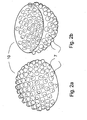
- a helmet liner according to the invention is shown as a perspective view as seen from above and as a perspective view as seen from below in the opposite direction, respectively.
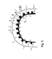
- Fig. 5-9 illustrates a possible manufacturing process for the helmet liner 10.
- the helmet liner exhibits undercut and may be manufactured by the following process:
- the forming of the flexible, air-proof foil 1 to a desired shape may in a preferred embodiment take place by vacuum moulding of the flexible, air-proof foil 1 on the first mould 3,4,5 through vacuum ducts 6 which at least are arranged through the slip mould 4.
- the forming of the flexible, air-proof foil 1 may also take place by press forming of the flexible, air-proof foil 1 on the mould 3,4,5.
- the shaped starting product 1,7,8 may itself be of such sufficiently good quality that further treatment or working is not required.
- the shaped starting product may for this reason itself constitute the final shape of the helmet liner 10.
- the helmet liner 10 into its final shape from the shaped starting product 1,7,8. This is in principle illustrated on fig. 9 . Such working may include, e.g., cutting, polishing, adaptments and adjustments of the shape of the helmet liner.
- the final shape of the helmet liner 10 may thus be manufactured from the shaped starting product 1,7,8.
- a helmet which includes a helmet liner according to the invention.
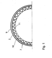
- a helmet comprises an outer shell 9 and an impact-absorbing helmet liner 10, in which the helmet liner comprises a layer provided with protruding, deformable and impact-absorbing hollow knobs distributed over an essential portion of the surface of the helmet liner as a protective layer.
- the shape and the orientation of the knobs are decided by the direction in which it is assumed that the knobs can have a protective effect, and not limited by the manufacturing methods of the background art.
- the hollow knobs 7 are arranged for deformation by crushing in case of external impact on the helmet, and that the helmet liner 10 with the hollow knobs 7 exhibits undercut.
- the helmet liner including the hollow knobs 7 are made of a softenable and/or flexible, air-proof film or foil 1 by moulding on a first mould 3,4,5 including a flexible slip mould 4, having secondary, relatively rigid and protruding forms 5, and an essentially rigid main mould 3, to form a shaped product 1 having a quantity of knobs or protrusions 7 and cavities 8, the shaped product being consolidated on the first mould 3,4,5 to a shaped starting product 1,7,8.
- the moulding of the helmet liner may be made on the first mould 3,4,5, e.g., by means of vacuum moulding or press forming.
- An impact-absorbing and preferably resilient layer 2 may advantageously be arranged between the external shell 9 and the helmet liner 10.
- the helmet with the helmet liner 10 may itself have a good fit, however, for additional comfort the helmet may further comprise an internal liner 11 arranged for resting on the head of a user.
- Several types of materials may be utilized for such a liner, such as fabrics of natural fibres, polymer textiles or other desirable materials.
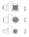
- the knobs on the helmet liner 10 are more closely illustrated on figs. 3a-3c and 4a-4c , and are advantageously distributed evenly or regularly on the entire helmet liner 10, e.g., by an arrangement of the knobs 7 spaced apart in a generally similar distance.
- the knobs 7 may also be arranged in an irregular or uneven pattern on the surface of the helmet liner 10 for such cases in which an equal deformation resistance is not desired for all incoming directions of impacts on the helmet.
- knobs 7 per area unit are arranged in the part of the helmet liner 10 which is arranged for protection of the brow 12, the top of the head 13 and the back head 14 of the user than there is arranged knobs 7 per area unit in the portion of the helmet liner 10 which is arranged for protection of the sides 15 of the head.
- knobs 7 have generally the same height. Alternatively, the height of the knobs 7 may vary.
- the base plan of the knobs 7 may advantageously be different from the circumference of the extrovert surfaces of the knobs 7.
- the base plan of the knobs may also be essentially a circular or elliptic shape. It is also possible having an essentially regular polygonic shape of the base plan of the knobs 7.
- the knobs 7 may have a base plan which is elliptic shape, e.g. circular, while the circumference of the extrovert surface has the shape of a regular polygon, e.g, a quadrangle, or the other way round. An example of such a combination is shown in fig. 3a .
- the knobs 7 have in a preferred embodiment essentially the shape of contracted or cut cones, such as shown in fig. 3b . Another alternative is that the knobs 7 may essentially have the shape of contracted or cut pyramids, such as shown in fig. 3c .
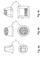
- fig. 4a-4c which illustrate that the extrovert surfaces of the knobs 7 may have different shapes.
- Fig. 4a shows a knob 7 having a straight cut shape
- fig. 4b shows a knob having a angular cut shape
- fig. 4c shows a knob 7 which exhibits a combination of both straight and angular cut shape.
- the material in the helmet liner 10 may, e.g., be plastic, metal, or a combination of plastic and metal.
- suitable materials is a thermoplastic, aluminium or steel, or a combination of thermoplastic and aluminium.
- the combination may, e.g., constitute a layer of thermoplastic and a layer of a metal foil, e.g., of aluminium, which are consolidated during manufacture of the helmet liner 10.
- a simplified and schematic view of a first mould 3,4,5 for manufacturing a helmet liner 10 with undercut is shown.
- the mould may stand on a base foundation like the mould 3,4,5 (not shown) on fig. 10 .
- the mould comprises a flexible slip mould 4 having secondary, relatively rigid and protruding shapes 5 on a main mould 3.
- the main mould is itself rigid, e.g., in the form of a rigid shell or a massive mould.
- the main mould 3 is stretchable to a fixed shape and collapsible.
- the mould 3,4,5 may be arranged for thermoforming, e.g., by vacuum moulding, and may be arranged for vacuum moulding by arranging vacuum ducts 6 at least through the slip mould 4. In another embodiment of the invention, vacuum ducts 6 are further arranged through the main mould 3. The mould 3,4,5 may alternatively be arranged for press forming.
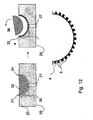
- a method for manufacturing a second mould 20 for a flexible slip mould 4 with secondary, protruding shapes 5 has been provided, in which the flexible slip mould 4 shall be utilized for production of a helmet liner 10 with undercut.
- the method may, e.g., comprise the following steps:
- Distance or centering pegs 27 may be attached in the second mould 20 in the desired amount and distribution.
- the mould material 25 may be a liquid or dry, ductile material which hardens or sets, e.g. by means of itself in contact with air, and is preferably a thermosetting plastic such as epoxy, or a combination of a thermosetting plastic and a filler material, e.g. wood.
- a temporary lining 28 may be applied inside the dome 29, helmet 29 or the object having a helmet shape 29, for adapting the size of the space between the second mould 20 with the recesses 26 and a second, complementary initial mould 30.
- the second, complementary initial mould 30 is manufactured by moulding inside the dome 29, the helmet 29 or the object with a helmet shape 29 with the temporary lining 28.
- the second mould 20 for a flexible slip mould 4 with secondary, protruding shapes 5, for production of a helmet liner 10 with undercut e.g. comprise the following features:
- the flexible slip mould 4 with secondary, protruding forms 5, for production of a helmet liner 10 with undercut, may be manufactured in the following manner:
- a helmet with a helmet liner according to the invention is provided with hollow knobs 7 which are arranged for permanent deformation or crushing by external impacts, and it is further shock absorbing, so that the forces from an impact against such helmet with a helmet liner 10 according to the invention are reduced as much as possible.
Landscapes
- Engineering & Computer Science (AREA)
- Mechanical Engineering (AREA)
- Manufacturing & Machinery (AREA)
- Helmets And Other Head Coverings (AREA)
- Moulds For Moulding Plastics Or The Like (AREA)
- Blow-Moulding Or Thermoforming Of Plastics Or The Like (AREA)
Claims (35)
- Verfahren zum Herstellen eines Helmfutters mit Hinterschneidung, dadurch gekennzeichnet, dass das Verfahren die folgenden Schritte umfasst:- Vorbereiten eines ersten Formwerkzeugs (3, 4, 5), welches ein flexibles Abziehformwerkzeug (4) umfasst, mit sekundären, relativ starren und vorspringenden Formen (5), angeordnet auf einem im Wesentlichen starren Hauptformwerkzeug (3);- Anordnen einer weichmachbaren und/oder flexiblen, luftdichten Schicht oder Folie (1) auf dem ersten Formwerkzeug (3, 4, 5), zum Formen der flexiblen, luftdichten Folie (1);- Formen der flexiblen, luftdichten Folie (1) auf dem ersten Formwerkzeug (3, 4, 5) zu einem geformten Produkt (1), mit einer Menge an Vorsprüngen (7) und Hohlräumen (8), wobei das geformte Produkt (1) Hinterschneidung zeigt;- Verfestigen des geformten Produkts (1), mit einer Menge an Vorsprüngen (7) und Hohlräumen (8), auf dem ersten Formwerkzeug (3, 4, 5) zu einem geformten Vorprodukt (1, 7, 8) mit Hinterschneidung;- Entfernen des geformten Vorprodukts (1, 7, 8) und des flexiblen Abziehformwerkzeugs (4), mit den sekundären Formen (5), von dem Hauptformwerkzeug (3);- Entfernen des flexiblen Abziehformwerkzeugs (4), mit den sekundären Formen (5), von dem geformten Vorprodukt (1, 7, 8).
- Verfahren nach Anspruch 1, dadurch gekennzeichnet, dass der Schritt des Formens der flexiblen, luftdichten Folie (1) zu einem geformten Produkt (1), mit einer Menge an Vorsprüngen (7) und Hohlräumen (8), Vakuumformen der flexiblen, luftdichten Folie (1) auf dem ersten Formwerkzeug (3, 4, 5) durch Vakuumkanäle (6) umfasst, welche wenigstens durch das Abziehformwerkzeug (4) angeordnet sind.
- Verfahren nach Anspruch 1, dadurch gekennzeichnet, dass der Schritt des Formens der flexiblen, luftdichten Folie (1) zu einem geformten Produkt (1), mit einer Menge an Vorsprüngen (7) und Hohlräumen (8), Pressformen der flexiblen, luftdichten Folie (1) auf dem ersten Formwerkzeug (3, 4, 5) umfasst.
- Verfahren nach einem der Ansprüche 1 bis 3, dadurch gekennzeichnet, dass es ferner den folgenden Schritt umfasst:- Herstellen der endgültigen Form des Helmfutters (10) aus dem geformten Vorprodukt (1, 7, 8).
- Verfahren nach einem der Ansprüche 1 bis 4, dadurch gekennzeichnet, dass es ferner den folgenden Schritt umfasst:- Weichmachen der flexiblen, luftdichten Folie (1) vor dem Schritt des Formens der flexiblen, luftdichten Folie (1).
- Verfahren nach Anspruch 5, dadurch gekennzeichnet, dass der Schritt des Weichmachens der flexiblen, luftdichten Folie (1) durch Erwärmen stattfindet.
- Verfahren nach einem der Ansprüche 1 bis 7, dadurch gekennzeichnet, dass es ferner den folgenden Schritt umfasst:- Verfestigen des geformten Vorprodukts (1, 7, 8) auf dem ersten Formwerkzeug (3, 4, 5) durch Kühlen und Aushärten nach dem Schritt des Formens der flexiblen, luftdichten Folie (1).
- Verfahren nach Anspruch 7, dadurch gekennzeichnet, dass der Schritt des Verfestigens des geformten Vorprodukts (1, 7, 8) durch Härten stattfindet.
- Verfahren nach einem der Ansprüche 1 bis 8, dadurch gekennzeichnet, dass es den folgenden Schritt umfasst:- Halten des Hauptformwerkzeugs (3) in einem gespannten und starren Zustand, dadurch, dass das Hauptformwerkzeug selbst starr ist, in der Form einer starren Schale oder einer massiven Form.
- Verfahren nach einem der Ansprüche 1 bis 8, dadurch gekennzeichnet, dass es den folgenden Schritt umfasst:- Halten des Hauptformwerkzeugs (3) in einem gespannten und starren Zustand, durch Zuführen von Fluiddruck im Inneren, in dem Hauptformwerkzeug (3).
- Verfahren nach einem der Ansprüche 1 bis 10, dadurch gekennzeichnet, dass es ferner den folgenden Schritt umfasst:- dass das Hauptformwerkzeug (3) und das flexible Formwerkzeug (4), mit den sekundären Formen (5), gleichzeitig von dem geformten Vorprodukt (1, 7, 8) entfernt werden.
- Verfahren nach einem der Ansprüche 1 bis 11, dadurch gekennzeichnet, dass es ferner den folgenden Schritt umfasst:- Spannen der flexiblen, luftdichten Folie (1) über das erste Formwerkzeug (3, 4, 5) durch Zuführen von Fluid, vorzugsweise eines Gases, wie etwa Luft, vor dem Schritt des Formens der flexiblen, luftdichten Folie (1) .
- Schlagdämpfendes Helmfutter (10), hergestellt durch das Verfahren nach Anspruch 1 bis 12, wobei das Helmfutter eine starre Lage umfasst, welche mit vorspringenden, verformbaren und schlagdämpfenden hohlen Noppen (7) versehen ist, verteilt auf einem wesentlichen Teil der Fläche des Helmfutters als eine schützende Lage, wobei die hohlen Noppen (7) zur Verformung durch Zerdrücken angeordnet sind, im Falle äußeren Schlags auf den Helm, und wobei das Helmfutter (10), mit den hohlen Noppen, Hinterschneidung zeigt, dadurch gekennzeichnet, dass die hohlen Noppen (7) in einer einzigen Lage angeordnet sind, wobei jede Noppe (7) von der Basisfläche des Helmfutters vorspringt, wobei die hohlen Noppen (7) zu der inneren Fläche des Helmfutters hin offen sind, derart, dass die hohlen Noppen (7) über einen wesentlichen Abschnitt der Fläche des Helmfutters als eine schützende Lage verteilt sind, und zur Verformung durch Zerdrücken angeordnet, im Falle äußeren Schlags auf den Helm.
- Helmfutter nach Anspruch 13, dadurch gekennzeichnet, dass es eine äußere Schale (9) aufweist, um so einen Helm zu bilden.
- Helmfutter nach Anspruch 13 oder 14, dadurch gekennzeichnet, dass es ferner eine schlagdämpfende und vorzugsweise elastische Lage (2) umfasst, angeordnet zwischen der äußeren Schale (9) und dem Helmfutter (10).
- Helmfutter nach einem der Ansprüche 13, 14 oder 15, dadurch gekennzeichnet, dass es ferner ein inneres Futter (11) umfasst, angeordnet, auf dem Kopf eines Benutzers aufzuliegen.
- Helmfutter nach einem der Ansprüche 13 bis 16, dadurch gekennzeichnet, dass die Noppen (7) gleichmäßig auf dem gesamten Helmfutter (10) verteilt sind, und dass die Noppen (7) sich in einer beabstandeten Anordnung mit einer im Allgemeinen gleichmäßigen Distanz voneinander befinden.
- Helmfutter nach einem der Ansprüche 13 bis 16, dadurch gekennzeichnet, dass mehr Noppen (7) pro Flächeneinheit angeordnet sind, in dem Teil des Helmfutters (10), welcher zum Schutz der Stirn (12), des Scheitels (13) und des Hinterkopfs (14) eines Benutzers angeordnet ist, als Noppen (7) pro Flächeneinheit angeordnet sind, in dem Teil des Helmfutters (10), welcher zum Schutz der Seiten (15) des Kopfes eines Benutzers angeordnet ist.
- Helmfutter nach einem der vorhergehenden Ansprüche 13 bis 18, dadurch gekennzeichnet, dass die Noppen (7) im Allgemeinen dieselbe Höhe aufweisen.
- Helmfutter nach einem der vorhergehenden Ansprüche 13 bis 19, wobei der Basisgrundriss der Noppen (7) anders ist als der Umriss der nach außen gerichteten Flächen der Noppen (7).
- Helmfutter nach einem der vorhergehenden Ansprüche 13 bis 20, dadurch gekennzeichnet, dass der Basisgrundriss der Noppen (7) im Wesentlichen eine kreisrunde oder elliptische Form aufweist.
- Helmfutter nach Anspruch 21, dadurch gekennzeichnet, dass die Noppen (7) im Wesentlichen die Form abgeschnittener Kegel aufweisen.
- Helmfutter nach einem der vorhergehenden Ansprüche 13 bis 21, dadurch gekennzeichnet, dass der Basisgrundriss der Noppen (7) im Wesentlichen eine regelmäßige polygonale Form aufweist.
- Helmfutter nach Anspruch 22, dadurch gekennzeichnet, dass die Noppen (7) im Wesentlichen die Form abgeschnittener Pyramiden aufweisen.
- Helmfutter nach einem der vorhergehenden Ansprüche 13 bis 23, dadurch gekennzeichnet, dass die Noppen (7) eine gerade oder eine schräge geschnittene Form aufweisen, oder eine Kombination einer geraden und einer schrägen geschnittenen Form.
- Helmfutter nach einem der vorhergehenden Ansprüche 13 bis 25, dadurch gekennzeichnet, dass das Material in dem Helmfutter (10) Kunststoff, Metall oder eine Kombination von Kunststoff und Metall ist.
- Helmfutter nach Anspruch 26, dadurch gekennzeichnet, dass das Material in dem Helmfutter (10) Thermoplast ist.
- Helmfutter nach Anspruch 26, dadurch gekennzeichnet, dass das Material in dem Helmfutter (10) Aluminium oder Stahl ist.
- Helmfutter nach Anspruch 26, dadurch gekennzeichnet, dass das Material in dem Helmfutter (10) eine Kombination von Thermoplast und Aluminium ist.
- Verfahren zum Herstellen eines zweiten Formwerkzeugs (20) für ein flexibles Abziehformwerkzeug (4), mit sekundären, vorspringenden Formen (5), wobei das flexible Abziehformwerkzeug (4) zur Herstellung eines Helmfutters (10) mit Hinterschneidung verwendet werden soll, dadurch gekennzeichnet, dass es die folgenden Schritte umfasst:- Herstellen eines ersten Ausgangsformwerkzeugs (21), welches im Wesentlichen der Form eines oberen Teils (16) des Kopfes einer Person entspricht, durch Herstellen eines Modells des oberen Teils (16) des Kopfes einer Person oder des Inneren (41) eines Helms (29) oder eines Objekts, welches eine Helmform (29) aufweist;- Anbringen von Noppen (22) in der gewünschten Menge und Verteilung auf dem gesamten ersten Ausgangsformwerkzeug (21) oder auf Teilen desselben, sodass eine Schablone (23) für das zweite Formwerkzeug (20) gebildet wird;- Anordnen der Schablone (23) in einem Behälter (24);- Einfüllen eines aushärtbaren Formwerkzeugmaterials (25) über die Schablone (23) in den Behälter (24);- Verfestigen des Formwerkzeugmaterials (25) in dem Behälter (24) mit der Schablone (23), zur Bildung des zweiten Formwerkzeugs (20), mit einer/-em oder mehreren Vertiefungen oder Hohlräumen (26), welche der äußeren Fläche der Noppen (22) entsprechen, und wobei das zweite Formwerkzeug (22), mit den Vertiefungen (26), angeordnet ist, zur Herstellung des flexiblen Abziehformwerkzeugs (4), mit sekundären, vorspringenden Formen (5);- Entfernen des zweiten Formwerkzeugs (20) aus dem Behälter (24); und- Entfernen der Schablone (23) von dem fertigen zweiten Formwerkzeug (20).
- Verfahren nach Anspruch 30, dadurch gekennzeichnet, dass es ferner den folgenden Schritt umfasst:- Anbringen von Distanz- oder Zentrierstiften (27) in dem zweiten Formwerkzeug (20) in der gewünschten Menge und Verteilung;
- Verfahren nach einem der Ansprüche 30 bis 31, dadurch gekennzeichnet, dass das Formwerkzeugmaterial (25) ein flüssiges oder trockenes duktiles Material ist, welches in Kontakt mit Luft oder durch Erwärmen härtet oder aushärtet, vorzugsweise ein hitzehärtbarer Kunststoff, wie etwa Epoxy, oder eine Kombination von einem hitzehärtbaren Kunststoff und einem Füllmaterial.
- Verfahren nach einem der Ansprüche 30 bis 32, dadurch gekennzeichnet, dass es ferner die folgenden Schritte umfasst:- Anwenden eines provisorischen Futters (28) im Inneren des Helms (29) oder des Objekts mit einer Helmform (29), zum Anpassen der Größe des Zwischenraums zwischen dem zweiten Formwerkzeug (20), mit den Vertiefungen (26), und einem zweiten, komplementären Ausgangsformwerkzeug (30);- Herstellen des zweiten, komplementären Ausgangsformwerkzeugs (30) durch Formen, im Inneren des Helms oder Objekts mit einer Helmform (29), mit dem provisorischen Futter (28).
- Zweites Formwerkzeug (20) für ein flexibles Abziehformwerkzeug (4), mit sekundären vorspringenden Formen (5), zur Herstellung eines Helmfutters (10) mit Hinterschneidung, dadurch gekennzeichnet, dass es die folgenden Merkmale umfasst:- dass das zweite Formwerkzeug (20) eine(n) oder mehrere Vertiefungen oder Hohlräume (26) umfasst, welche(r) angeordnet ist/sind, Formmasse (32) aufzunehmen, und einen oder mehrere Zentrierstifte (27), welche in dem zweiten Formwerkzeug (20), mit den Vertiefungen (26), verteilt sind, und angeordnet zum Zentrieren eines zweiten, komplementären Ausgangsformwerkzeugs (30) in dem zweiten Formwerkzeug (20), mit den Vertiefungen (26);- dass das zweite Ausgangsformwerkzeug (30) einen Durchmesser aufweist, welcher kleiner ist als der Durchmesser des zweiten Formwerkzeugs (20), und wobei es gestaltet ist, um in dem zweiten Formwerkzeug (20) angeordnet zu werden, sodass ein Zwischenraum (31) gebildet wird, zwischen dem zweiten Formwerkzeug (20), mit den Vertiefungen (26), und dem zweiten Ausgangsformwerkzeug (30), welcher angeordnet ist, Formmasse (32) aufzunehmen;- so dass, durch Verfestigung von Formmasse (32) in dem Zwischenraum (31), ein flexibles Abziehformwerkzeug (4), mit sekundären, vorspringenden Formen (5), gebildet wird, zum Anordnen auf einem fixen Formwerkzeug (3) mit einer Form, komplementär zu dem zweiten Ausgangsformwerkzeug (30).
- Verfahren zum Herstellen eines flexiblen Abziehformwerkzeugs (4), mit sekundären, vorspringenden Formen (5), zur Herstellung eines Helmfutters (10) mit Hinterschneidung, dadurch gekennzeichnet, dass es die folgenden Schritte umfasst:- Einfüllen von Formmasse (32) in ein zweites Formwerkzeug (20), welches eine(n) oder mehrere Vertiefungen oder Hohlräume (26) und einen oder mehrere Zentrierstifte (27) umfasst, welche in dem zweiten Formwerkzeug (20), mit den Vertiefungen (26), verteilt sind, und angeordnet zum Zentrieren eines zweiten Ausgangsformwerkzeugs (30) in dem zweiten Formwerkzeug (20), mit den Vertiefungen (26);- Anordnen eines zweiten Ausgangsformwerkzeugs (30) in dem zweiten Formwerkzeug (20) mit der Formmasse (32), sodass ein Zwischenraum (31) hin zu dem Formwerkzeug gebildet wird;- Verfestigen der Formmasse (32) zu dem flexiblen Abziehformwerkzeug (4), mit sekundären, vorspringenden Formen (5);- Entfernen des zweiten Ausgangsformwerkzeugs (30) von dem verfestigten Abziehformwerkzeug (4) in dem zweiten Formwerkzeug (20) mit dem verfestigten, flexiblen Abziehformwerkzeug (4);- Herausziehen des flexiblen Abziehformwerkzeugs (4) aus dem zweiten Formwerkzeug (20).
Applications Claiming Priority (2)
| Application Number | Priority Date | Filing Date | Title |
|---|---|---|---|
| NO20041475A NO323512B1 (no) | 2004-04-07 | 2004-04-07 | Stopeform for framstilling av en hjelmfôring. |
| PCT/NO2005/000115 WO2005097467A1 (en) | 2004-04-07 | 2005-04-06 | Helmet, helmet liner with undercut, and method of manufacturing the same |
Publications (2)
| Publication Number | Publication Date |
|---|---|
| EP1744868A1 EP1744868A1 (de) | 2007-01-24 |
| EP1744868B1 true EP1744868B1 (de) | 2008-07-09 |
Family
ID=34859254
Family Applications (1)
| Application Number | Title | Priority Date | Filing Date |
|---|---|---|---|
| EP05734936A Expired - Lifetime EP1744868B1 (de) | 2004-04-07 | 2005-04-06 | Helm, helmfutter mit hinterschneidung und herstellungsverfahren dafür |
Country Status (10)
| Country | Link |
|---|---|
| US (1) | US7676854B2 (de) |
| EP (1) | EP1744868B1 (de) |
| JP (1) | JP2007532344A (de) |
| KR (1) | KR101199756B1 (de) |
| CN (1) | CN1997506B (de) |
| AT (1) | ATE400421T1 (de) |
| DE (1) | DE602005008039D1 (de) |
| ES (1) | ES2309745T3 (de) |
| NO (1) | NO323512B1 (de) |
| WO (1) | WO2005097467A1 (de) |
Cited By (1)
| Publication number | Priority date | Publication date | Assignee | Title |
|---|---|---|---|---|
| AT512078A1 (de) * | 2011-11-09 | 2013-05-15 | Karall Gerhard Ing | Helmkalotte |
Families Citing this family (105)
| Publication number | Priority date | Publication date | Assignee | Title |
|---|---|---|---|---|
| US8256147B2 (en) | 2004-11-22 | 2012-09-04 | Frampton E. Eliis | Devices with internal flexibility sipes, including siped chambers for footwear |
| US12290134B2 (en) | 2004-11-22 | 2025-05-06 | Frampton E. Ellis | Footwear or orthotic sole with microprocessor control of a structural or support element with magnetorheological fluid |
| US7802320B2 (en) * | 2005-06-30 | 2010-09-28 | Morgan Don E | Helmet padding |
| GB2431859A (en) * | 2005-10-31 | 2007-05-09 | Lloyd | A body protecting device comprising an array of energy absorbing cells |
| US8125796B2 (en) | 2007-11-21 | 2012-02-28 | Frampton E. Ellis | Devices with faraday cages and internal flexibility sipes |
| KR200447426Y1 (ko) * | 2007-12-05 | 2010-01-25 | 이상근 | 완충패드가 설치된 헬멧 |
| US8533869B1 (en) * | 2008-02-19 | 2013-09-17 | Noggin Group LLC | Energy absorbing helmet underwear |
| FR2930408B1 (fr) * | 2008-04-24 | 2011-02-11 | Salomon Sa | Casque avec moyen de personnalisation permettant la variation du volume interieur |
| DE102008028709B4 (de) * | 2008-06-17 | 2010-07-22 | Schuberth Gmbh | Schutzhelm |
| US20100000009A1 (en) * | 2008-07-02 | 2010-01-07 | Morgan Donald E | Compressible Liner for Impact Protection |
| KR100897434B1 (ko) * | 2008-10-15 | 2009-05-25 | 주식회사 나노텍세라믹스 | 경량 헬멧쉘 |
| KR101252119B1 (ko) * | 2011-03-25 | 2013-04-12 | 고환복 | 레저 스포츠용 헬멧 |
| TWI494066B (zh) * | 2009-12-18 | 2015-08-01 | Donald Edward Morgan | 用於衝擊保護的可壓縮襯裡 |
| US8235461B2 (en) * | 2010-01-21 | 2012-08-07 | Cohen Elie | Ventilated seat using shock absorbing material |
| EP2389822A1 (de) | 2010-05-26 | 2011-11-30 | The Royal College of Art | Helm |
| US8726424B2 (en) | 2010-06-03 | 2014-05-20 | Intellectual Property Holdings, Llc | Energy management structure |
| GB2497491B (en) | 2010-10-06 | 2016-05-04 | Cortex Armour Inc | Shock absorbing layer with independent elements |
| CN103635112B (zh) * | 2011-02-09 | 2015-12-23 | 6D头盔有限责任公司 | 头盔全向能量管理系统 |
| US11324273B2 (en) | 2011-02-09 | 2022-05-10 | 6D Helmets, Llc | Omnidirectional energy management systems and methods |
| US10561192B2 (en) | 2011-02-09 | 2020-02-18 | 6D Helmets, Llc | Omnidirectional energy management systems and methods |
| US11766085B2 (en) | 2011-02-09 | 2023-09-26 | 6D Helmets, Llc | Omnidirectional energy management systems and methods |
| US12336585B2 (en) | 2011-02-09 | 2025-06-24 | 6D Helmets, Llc | Omnidirectional energy management systems and methods |
| USD670869S1 (en) | 2011-05-09 | 2012-11-13 | A7 Helmet Systems, Llc | Helmet padding |
| USD670870S1 (en) | 2011-05-09 | 2012-11-13 | A7 Helmet Systems, Llc | Helmet padding |
| USD670868S1 (en) | 2011-05-09 | 2012-11-13 | A7 Helmet Systems, Llc | Helmet padding |
| US8566967B2 (en) | 2011-05-19 | 2013-10-29 | Warrior Sports, Inc. | Helmet with neck roll |
| US9032558B2 (en) | 2011-05-23 | 2015-05-19 | Lionhead Helmet Intellectual Properties, Lp | Helmet system |
| USD666779S1 (en) | 2011-06-15 | 2012-09-04 | A7 Helmet Systems, Llc | Helmet padding |
| USD679058S1 (en) | 2011-07-01 | 2013-03-26 | Intellectual Property Holdings, Llc | Helmet liner |
| US9516910B2 (en) | 2011-07-01 | 2016-12-13 | Intellectual Property Holdings, Llc | Helmet impact liner system |
| USD683079S1 (en) | 2011-10-10 | 2013-05-21 | Intellectual Property Holdings, Llc | Helmet liner |
| US9462843B2 (en) | 2011-12-16 | 2016-10-11 | Viconic Defense Inc. | Cushioning helmet liner |
| US9420843B2 (en) * | 2011-12-16 | 2016-08-23 | Oakwood Energy Management, Inc. | Rebounding cushioning helmet liner |
| DE102012022542A1 (de) * | 2011-12-19 | 2013-06-20 | Oliver Schimpf | Schutzhelm; Verfahren zur Verminderung oder Verhinderung einer Kopfverletzung |
| US9392833B2 (en) | 2012-01-06 | 2016-07-19 | Michcar Partners, Llc | Protective helmet |
| US9113672B2 (en) | 2012-01-06 | 2015-08-25 | Michcar Partners, Llc | Protective helmet |
| WO2013123113A1 (en) * | 2012-02-16 | 2013-08-22 | Bonin Walter | Personal impact protection device |
| US9320311B2 (en) | 2012-05-02 | 2016-04-26 | Intellectual Property Holdings, Llc | Helmet impact liner system |
| US10834987B1 (en) * | 2012-07-11 | 2020-11-17 | Apex Biomedical Company, Llc | Protective liner for helmets and other articles |
| US8640267B1 (en) * | 2012-09-14 | 2014-02-04 | Yochanan Cohen | Protective helmet |
| US9578917B2 (en) | 2012-09-14 | 2017-02-28 | Pidyon Controls Inc. | Protective helmets |
| US9894953B2 (en) | 2012-10-04 | 2018-02-20 | Intellectual Property Holdings, Llc | Helmet retention system |
| US9603408B2 (en) * | 2012-10-05 | 2017-03-28 | Elwood J. B. Simpson | Football helmet having improved impact absorption |
| US9572390B1 (en) * | 2012-10-05 | 2017-02-21 | Elwood J. B. Simpson | Football helmet having improved impact absorption |
| USD710058S1 (en) * | 2012-11-08 | 2014-07-29 | Gary V. Johnson | Protective sports cap |
| US9487110B2 (en) | 2014-03-05 | 2016-11-08 | Pidyon Controls Inc. | Car seat |
| US10220734B2 (en) | 2013-03-05 | 2019-03-05 | Pidyon Controls Inc. | Car seat |
| US8911015B2 (en) | 2013-03-05 | 2014-12-16 | Yochanan Cohen | Car seat |
| CN104082898A (zh) * | 2013-04-01 | 2014-10-08 | 陈曦 | 一种基于纳米多孔能量吸收材料的头盔 |
| GB2513598B (en) * | 2013-04-30 | 2018-06-06 | Albertelli Aldino | Protective headwear |
| FR3009167B1 (fr) * | 2013-08-05 | 2016-01-01 | Salomon Sas | Casque |
| USD733972S1 (en) | 2013-09-12 | 2015-07-07 | Intellectual Property Holdings, Llc | Helmet |
| AU2014342635B2 (en) | 2013-10-28 | 2019-07-11 | Team Wendy, Llc | Helmet retention system |
| CN103660304B (zh) * | 2013-11-29 | 2017-01-11 | 航宇救生装备有限公司 | 个体防护头盔内部热塑性衬垫及其制作方法 |
| AU2014373788B2 (en) * | 2013-12-30 | 2019-03-28 | David Burns | Protective swim cap |
| USD747040S1 (en) | 2014-02-10 | 2016-01-05 | Robert J. Milam | Helmet |
| US9415708B2 (en) | 2014-02-18 | 2016-08-16 | Oakwood Energy Management, Inc. | Conformable energy absorber |
| US9975032B2 (en) * | 2014-03-24 | 2018-05-22 | Mark Frey | Concussive helmet |
| CN104019535B (zh) * | 2014-06-24 | 2017-08-11 | 珠海格力电器股份有限公司 | 壁挂式空调器 |
| US9616782B2 (en) | 2014-08-29 | 2017-04-11 | Pidyon Controls Inc. | Car seat vehicle connection system, apparatus, and method |
| US9332799B1 (en) * | 2014-10-14 | 2016-05-10 | Helmet Technologies LLC | Protective apparatus and method for dissipating force |
| US10327482B1 (en) * | 2014-10-14 | 2019-06-25 | Helmet Technologies LLC | Apparatus and method for dissipating force |
| USD793625S1 (en) | 2014-10-23 | 2017-08-01 | Intellectual Property Holdings, Llc | Helmet |
| JP6715846B2 (ja) * | 2014-12-23 | 2020-07-01 | サフィーロ・ソシエタ・アツィオナリア・ファブリカ・イタリアナ・ラボラツィオーネ・オッチアリ・エス・ピー・エー | スポーツ用、特にスキーをするときに使用する保護ヘルメット |
| WO2016116872A1 (en) * | 2015-01-21 | 2016-07-28 | Dainese S.P.A. | Helmet and process for manufacturing such a helmet |
| US20160242486A1 (en) * | 2015-02-22 | 2016-08-25 | Maurice Harris | Impact diverting helmet system |
| US10537149B2 (en) | 2015-03-02 | 2020-01-21 | Viconic Sporting Llc | Multi-stage energy absorber |
| CN104720175B (zh) * | 2015-04-13 | 2017-03-01 | 步向义 | 一种具有提示和报警功能的安全帽 |
| MX2017013976A (es) | 2015-05-12 | 2018-03-14 | Pidyon Controls Inc | Asiento para automovil y sistema de conexion. |
| US11419381B2 (en) * | 2015-05-19 | 2022-08-23 | Maurício Paranhos Torres | Cranial protection cell |
| WO2017120378A1 (en) * | 2016-01-08 | 2017-07-13 | VICIS, Inc. | Manufacturing impact absorbing structures for an athletic helmet |
| EP3410881B1 (de) | 2016-02-02 | 2020-10-28 | Mips AB | Helm |
| CN108811487B (zh) * | 2016-02-25 | 2022-04-08 | 康泰体育有限公司 | 防护头盔 |
| US20170332719A1 (en) * | 2016-05-23 | 2017-11-23 | Bennie Aaron | Flexible Head Protector |
| USD924544S1 (en) * | 2016-06-30 | 2021-07-13 | Mako International, Llc | Headwear with protective feature |
| US11206878B2 (en) | 2016-08-16 | 2021-12-28 | Timothy W. Markison | Body impact protection system |
| US12281683B2 (en) | 2016-08-16 | 2025-04-22 | Timothy W. Markison | Defusing cell for impact force defusion |
| CN106236138A (zh) * | 2016-08-19 | 2016-12-21 | 西南医科大学 | 基于瑞利波的颅内压无创监测仪 |
| US11147334B2 (en) * | 2016-10-07 | 2021-10-19 | William STECK | Apparatus and method for improving impact performance of helmets |
| WO2018144131A1 (en) * | 2016-12-06 | 2018-08-09 | KIRSH Helmets, Inc. | Impact-dissipating liners and methods of fabricating impact-dissipating liners |
| CN106690631A (zh) * | 2016-12-30 | 2017-05-24 | 重庆市合川区通用汽车配件制造厂 | 一种多功能摩托车头盔 |
| US11191316B2 (en) | 2017-04-26 | 2021-12-07 | Fend Corp. | Collapsible helmet |
| US10542788B2 (en) | 2017-05-11 | 2020-01-28 | Safer Sports, LLC | Football helmet having three energy absorbing layers |
| US10201208B1 (en) * | 2017-07-26 | 2019-02-12 | Ronnie Z. Bochner | Foldable helmet |
| CN107692650A (zh) * | 2017-11-08 | 2018-02-16 | 岳敏行 | 一种学生防震坐垫 |
| CN109892736A (zh) * | 2017-12-07 | 2019-06-18 | 洛阳尖端技术研究院 | 头盔防护垫、头盔及制备头盔防护垫的方法 |
| CA3047771A1 (en) | 2018-06-29 | 2019-12-29 | Bauer Hockey, Ltd. | Methods and systems for design and production of customized wearable equipment |
| US11331545B2 (en) | 2018-09-14 | 2022-05-17 | Timothy W. Markison | Force focusing golf club |
| ES2887074T3 (es) * | 2018-10-16 | 2021-12-21 | Lazer Sport Nv | Un casco para protección contra impactos |
| WO2020130890A1 (en) * | 2018-12-17 | 2020-06-25 | Saab Ab | A mould body assembly and a method of forming a hollow article |
| US11766083B2 (en) * | 2019-03-25 | 2023-09-26 | Tianqi Technology Co (Ningbo) Ltd | Helmet |
| USD927073S1 (en) | 2019-04-16 | 2021-08-03 | Safer Sports, LLC | Football helmet |
| US10869520B1 (en) | 2019-11-07 | 2020-12-22 | Lionhead Helmet Intellectual Properties, Lp | Helmet |
| USD935106S1 (en) | 2019-11-22 | 2021-11-02 | Safer Sports, LLC | Helmet |
| US20210153592A1 (en) | 2019-11-22 | 2021-05-27 | Safer Sports, LLC DBA Light Helmets | Soft shell helmet |
| CN111011973A (zh) * | 2019-12-24 | 2020-04-17 | 江苏陶朱消防科技有限公司 | 一种抗冲击耐穿透消防头盔 |
| US10905187B1 (en) | 2020-03-30 | 2021-02-02 | Gwenventions, Llc | Collapsible helmet |
| GB202009991D0 (en) * | 2020-06-30 | 2020-08-12 | Mips Ab | Pad and padding |
| CN113211781B (zh) * | 2021-01-25 | 2022-11-29 | 嘉兴嘉创智医疗设备有限公司 | 一种利用3d打印机打印矫形头盔的方法及3d打印机 |
| US11547166B1 (en) | 2022-02-11 | 2023-01-10 | Lionhead Helmet Intellectual Properties, Lp | Helmet |
| US11641904B1 (en) | 2022-11-09 | 2023-05-09 | Lionhead Helmet Intellectual Properties, Lp | Helmet |
| GB2626329A (en) * | 2023-01-17 | 2024-07-24 | Design Blue Ltd | Impact liner system with airflow channels |
| TWI889263B (zh) * | 2024-03-27 | 2025-07-01 | 集群科技有限公司 | 製造防護安全帽的纏線設備及防護安全帽的製造方法 |
| US12121095B1 (en) | 2024-04-24 | 2024-10-22 | Lionhead Helmet Intellectual Properties, Lp | Helmet |
| KR102921563B1 (ko) * | 2024-09-06 | 2026-01-30 | 김봉준 | 냉감헬멧 |
Family Cites Families (39)
| Publication number | Priority date | Publication date | Assignee | Title |
|---|---|---|---|---|
| US3378888A (en) | 1965-10-19 | 1968-04-23 | Holley Plastics Company | Structure for vacuum forming of thermoplastic material on undercut flexible molds |
| US3425061A (en) | 1967-09-08 | 1969-02-04 | Daniel D Webb | Energy absorbing helmet shell |
| US3673609A (en) | 1971-01-27 | 1972-07-04 | Us Navy | Protective helmet |
| US3877076A (en) | 1974-05-08 | 1975-04-15 | Mine Safety Appliances Co | Safety hat energy absorbing liner |
| US4023213A (en) * | 1976-05-17 | 1977-05-17 | Pepsico, Inc. | Shock-absorbing system for protective equipment |
| DE7810225U1 (de) | 1978-04-06 | 1978-07-13 | Uvex Winter Optik Gmbh, 8510 Fuerth | Schutzhelm |
| US4290149A (en) * | 1978-05-12 | 1981-09-22 | Gentex Corporation | Method of making an individually fitted helmet |
| JPS5929713B2 (ja) * | 1979-01-31 | 1984-07-23 | 鐘淵化学工業株式会社 | アンダカツトを有する布帛熱成形型および成形方法 |
| DE3035265A1 (de) | 1980-09-18 | 1982-04-29 | AOE Plastic GmbH, 8000 München | Sicherheitshelm |
| FR2523411A1 (fr) | 1982-03-22 | 1983-09-23 | Renault | Casque a structure alveolaire, notamment pour cycliste ou cyclomotoriste |
| US4432099A (en) * | 1982-07-09 | 1984-02-21 | Gentex Corporation | Individually fitted helmet liner |
| JPS59185621A (ja) | 1983-04-06 | 1984-10-22 | Sekisui Plastics Co Ltd | 緩衝包装材の製造方法 |
| US4586200A (en) * | 1984-03-26 | 1986-05-06 | Poon Melvyn C | Protective crash helmet |
| US4724549A (en) | 1984-12-11 | 1988-02-16 | Airsorb Pty. Ltd. | Protective helmet and locking means |
| JPS63221020A (ja) * | 1987-03-11 | 1988-09-14 | Zojirushi Vacuum Bottle Co | アンダ−カツトを有する成型品の製造方法 |
| US5366685A (en) * | 1989-07-18 | 1994-11-22 | Idemitsu Petrochemical Co., Ltd. | Process of molding thermoplastic sheet by plug assist vacuum forming |
| US5035009A (en) * | 1990-09-27 | 1991-07-30 | Riddell, Inc. | Protective helmet and liner |
| DE4129339A1 (de) | 1991-09-04 | 1993-03-11 | Toho Zweiradzubehoergesellscha | Radfahrerhelm |
| US5361419A (en) * | 1991-09-12 | 1994-11-08 | Protector Development | Helmet with sound ducts |
| US5298208A (en) | 1991-11-01 | 1994-03-29 | Athletic Helmet, Inc. | Method for molding a protective helmet |
| JPH05287603A (ja) | 1992-04-06 | 1993-11-02 | Yamaha Motor Co Ltd | ヘルメット |
| US5829065A (en) * | 1994-02-15 | 1998-11-03 | Cahill; Kevin J. | Industrial protective helmet |
| IT1273784B (it) * | 1994-02-17 | 1997-07-10 | Agv Spa | Apparecchiatura e procedimento per la decorazione di caschi mediante rivestimento con un foglio in materiale sintetico predecorato |
| JP3236196B2 (ja) * | 1995-08-10 | 2001-12-10 | 吉田化学株式会社 | 真空成形用型とそれを用いた真空成形方法 |
| JP2000502575A (ja) | 1995-12-22 | 2000-03-07 | ヘキスト・セラニーズ・コーポレーション | 三次元の成形繊維生成物を含む靴 |
| US5731062A (en) | 1995-12-22 | 1998-03-24 | Hoechst Celanese Corp | Thermoplastic three-dimensional fiber network |
| DE19621004C2 (de) | 1996-05-24 | 2000-02-24 | Schuberth Werk Kg | Schutzhelm, insbesondere militärischer Schutzhelm |
| AU8021898A (en) | 1997-07-09 | 1999-02-08 | Taexpa, S.A. | Impact absorption system applicable to head protection helmets |
| US5950244A (en) * | 1998-01-23 | 1999-09-14 | Sport Maska Inc. | Protective device for impact management |
| US6453476B1 (en) * | 2000-09-27 | 2002-09-24 | Team Wendy, Llc | Protective helmet |
| US6536052B2 (en) | 2000-12-04 | 2003-03-25 | Lucky Bell Plastic Factory Ltd. | Safety helmets with cellular textile composite structure as energy absorber |
| US6808154B2 (en) * | 2001-03-22 | 2004-10-26 | Column & Post., Inc. | Mold and molding process |
| US6749794B2 (en) * | 2001-08-13 | 2004-06-15 | R + S Technik Gmbh | Method and apparatus for molding components with molded-in surface texture |
| US20030047847A1 (en) * | 2001-09-13 | 2003-03-13 | Fitzell James Richard | Thermoforming method and apparatus |
| US20030197302A1 (en) * | 2002-04-17 | 2003-10-23 | Srimannarayana Kakarala | Thermoplastic olefin composition, process for making the composition and method for negative vacuum forming articles therefrom |
| US6743385B2 (en) * | 2002-05-22 | 2004-06-01 | Swei Mu Wang | Wear-resistant three-dimensional foamable structure and the method for manufacturing it |
| US20060162053A1 (en) * | 2003-01-09 | 2006-07-27 | Lee Dong S | Method for manufacturing safety helmet and safety helmet manufactured with the same |
| US7413698B2 (en) * | 2004-06-01 | 2008-08-19 | Novo Foam Products Llc | Method of molding load-bearing articles from compressible cores and heat malleable coverings |
| US20070209098A1 (en) * | 2006-03-10 | 2007-09-13 | Stephen Peart | Helmet having interior ventilation channels |
-
2004
- 2004-04-07 NO NO20041475A patent/NO323512B1/no not_active IP Right Cessation
-
2005
- 2005-04-06 DE DE602005008039T patent/DE602005008039D1/de not_active Expired - Lifetime
- 2005-04-06 ES ES05734936T patent/ES2309745T3/es not_active Expired - Lifetime
- 2005-04-06 KR KR1020067023200A patent/KR101199756B1/ko not_active Expired - Fee Related
- 2005-04-06 CN CN2005800184697A patent/CN1997506B/zh not_active Expired - Fee Related
- 2005-04-06 JP JP2007507265A patent/JP2007532344A/ja active Pending
- 2005-04-06 WO PCT/NO2005/000115 patent/WO2005097467A1/en not_active Ceased
- 2005-04-06 EP EP05734936A patent/EP1744868B1/de not_active Expired - Lifetime
- 2005-04-06 AT AT05734936T patent/ATE400421T1/de not_active IP Right Cessation
- 2005-04-07 US US11/100,627 patent/US7676854B2/en not_active Expired - Fee Related
Cited By (2)
| Publication number | Priority date | Publication date | Assignee | Title |
|---|---|---|---|---|
| AT512078A1 (de) * | 2011-11-09 | 2013-05-15 | Karall Gerhard Ing | Helmkalotte |
| AT512078B1 (de) * | 2011-11-09 | 2013-11-15 | Karall Gerhard Ing | Helmkalotte |
Also Published As
| Publication number | Publication date |
|---|---|
| WO2005097467A1 (en) | 2005-10-20 |
| KR20070052239A (ko) | 2007-05-21 |
| CN1997506B (zh) | 2012-06-13 |
| JP2007532344A (ja) | 2007-11-15 |
| ATE400421T1 (de) | 2008-07-15 |
| HK1108856A1 (en) | 2008-05-23 |
| DE602005008039D1 (de) | 2008-08-21 |
| US7676854B2 (en) | 2010-03-16 |
| CN1997506A (zh) | 2007-07-11 |
| US20050246824A1 (en) | 2005-11-10 |
| NO323512B1 (no) | 2007-06-04 |
| NO20041475L (no) | 2005-10-10 |
| NO20041475D0 (no) | 2004-04-07 |
| ES2309745T3 (es) | 2008-12-16 |
| KR101199756B1 (ko) | 2012-11-08 |
| EP1744868A1 (de) | 2007-01-24 |
Similar Documents
| Publication | Publication Date | Title |
|---|---|---|
| US7676854B2 (en) | Helmet, helmet liner and method for manufacturing the same | |
| CN2538173Y (zh) | 具有胞腔室式织品复合构造以作为能量吸收的安全帽 | |
| JP2007532344A5 (de) | ||
| US10939719B2 (en) | Energy dissipating helmet | |
| US20210197494A1 (en) | 3d printing support structure and design method | |
| EP0465169B1 (de) | Verfahren zur Herstellung von Gebläseschaufeln | |
| US10583331B2 (en) | Skin body structure for ball | |
| EP2067596B1 (de) | Verfahren und Vorrichtung zur Herstellung eines Gegenstandes mit einem leeren Raum | |
| WO1995015246A1 (en) | Method for molding article with vulnerable insert | |
| HK1108856B (en) | Helmet, helmet liner with undercut, and method of manufacturing the same | |
| WO2025126919A1 (ja) | 造形物製造方法 | |
| NO323511B1 (no) | Hjelmforing og fremgangsmate for fremstilling av samme | |
| WO2001032407A1 (en) | Device for the production of optical lenses of polymerizable material | |
| EP1699673B2 (de) | Lenkrad und verfahren zur herstellung eines lenkrades | |
| CN113232460B (zh) | 一种减震轮胎及其制作工艺 | |
| JP5920865B2 (ja) | 衝撃緩和帽子の製造方法及びその製造方法で衝撃緩和帽子を製造する装置 | |
| EP4197766A1 (de) | Verfahren zum mikroformen von mikrostrukturierten folien und linsen | |
| KR101272476B1 (ko) | 요철 형상을 갖춘 장식커버지 및 그 제조방법 | |
| EP2581063B1 (de) | Vorform zur Herstellung eines Schafts für prothetische Gliedmaßen | |
| JP2018036488A (ja) | ブロッキングリング、ブロッキングリングの製造方法、及び眼鏡レンズの製造方法 | |
| JP4271828B2 (ja) | 繊維集合体成形用金型 | |
| JP2004130630A (ja) | 衝撃吸収材の製造方法 | |
| HK1035224B (en) | Shock absorbing component and construction method | |
| HK1035224A1 (en) | Shock absorbing component and construction method | |
| KR20150008628A (ko) | 콘택트렌즈의 성형 몰드 및 그에 의하여 제조된 콘택트렌즈 |
Legal Events
| Date | Code | Title | Description |
|---|---|---|---|
| PUAI | Public reference made under article 153(3) epc to a published international application that has entered the european phase |
Free format text: ORIGINAL CODE: 0009012 |
|
| 17P | Request for examination filed |
Effective date: 20061107 |
|
| AK | Designated contracting states |
Kind code of ref document: A1 Designated state(s): AT BE BG CH CY CZ DE DK EE ES FI FR GB GR HU IE IS IT LI LT LU MC NL PL PT RO SE SI SK TR |
|
| 17Q | First examination report despatched |
Effective date: 20070307 |
|
| DAX | Request for extension of the european patent (deleted) | ||
| GRAP | Despatch of communication of intention to grant a patent |
Free format text: ORIGINAL CODE: EPIDOSNIGR1 |
|
| GRAS | Grant fee paid |
Free format text: ORIGINAL CODE: EPIDOSNIGR3 |
|
| GRAA | (expected) grant |
Free format text: ORIGINAL CODE: 0009210 |
|
| AK | Designated contracting states |
Kind code of ref document: B1 Designated state(s): AT BE BG CH CY CZ DE DK EE ES FI FR GB GR HU IE IS IT LI LT LU MC NL PL PT RO SE SI SK TR |
|
| REG | Reference to a national code |
Ref country code: GB Ref legal event code: FG4D |
|
| REG | Reference to a national code |
Ref country code: CH Ref legal event code: EP |
|
| REF | Corresponds to: |
Ref document number: 602005008039 Country of ref document: DE Date of ref document: 20080821 Kind code of ref document: P |
|
| REG | Reference to a national code |
Ref country code: IE Ref legal event code: FG4D |
|
| REG | Reference to a national code |
Ref country code: ES Ref legal event code: FG2A Ref document number: 2309745 Country of ref document: ES Kind code of ref document: T3 |
|
| PG25 | Lapsed in a contracting state [announced via postgrant information from national office to epo] |
Ref country code: LT Free format text: LAPSE BECAUSE OF FAILURE TO SUBMIT A TRANSLATION OF THE DESCRIPTION OR TO PAY THE FEE WITHIN THE PRESCRIBED TIME-LIMIT Effective date: 20080709 Ref country code: IS Free format text: LAPSE BECAUSE OF FAILURE TO SUBMIT A TRANSLATION OF THE DESCRIPTION OR TO PAY THE FEE WITHIN THE PRESCRIBED TIME-LIMIT Effective date: 20081109 |
|
| PG25 | Lapsed in a contracting state [announced via postgrant information from national office to epo] |
Ref country code: SI Free format text: LAPSE BECAUSE OF FAILURE TO SUBMIT A TRANSLATION OF THE DESCRIPTION OR TO PAY THE FEE WITHIN THE PRESCRIBED TIME-LIMIT Effective date: 20080709 Ref country code: PT Free format text: LAPSE BECAUSE OF FAILURE TO SUBMIT A TRANSLATION OF THE DESCRIPTION OR TO PAY THE FEE WITHIN THE PRESCRIBED TIME-LIMIT Effective date: 20081209 Ref country code: AT Free format text: LAPSE BECAUSE OF FAILURE TO SUBMIT A TRANSLATION OF THE DESCRIPTION OR TO PAY THE FEE WITHIN THE PRESCRIBED TIME-LIMIT Effective date: 20080709 Ref country code: BG Free format text: LAPSE BECAUSE OF FAILURE TO SUBMIT A TRANSLATION OF THE DESCRIPTION OR TO PAY THE FEE WITHIN THE PRESCRIBED TIME-LIMIT Effective date: 20081009 Ref country code: FI Free format text: LAPSE BECAUSE OF FAILURE TO SUBMIT A TRANSLATION OF THE DESCRIPTION OR TO PAY THE FEE WITHIN THE PRESCRIBED TIME-LIMIT Effective date: 20080709 |
|
| PG25 | Lapsed in a contracting state [announced via postgrant information from national office to epo] |
Ref country code: BE Free format text: LAPSE BECAUSE OF FAILURE TO SUBMIT A TRANSLATION OF THE DESCRIPTION OR TO PAY THE FEE WITHIN THE PRESCRIBED TIME-LIMIT Effective date: 20080709 |
|
| PG25 | Lapsed in a contracting state [announced via postgrant information from national office to epo] |
Ref country code: DK Free format text: LAPSE BECAUSE OF FAILURE TO SUBMIT A TRANSLATION OF THE DESCRIPTION OR TO PAY THE FEE WITHIN THE PRESCRIBED TIME-LIMIT Effective date: 20080709 Ref country code: EE Free format text: LAPSE BECAUSE OF FAILURE TO SUBMIT A TRANSLATION OF THE DESCRIPTION OR TO PAY THE FEE WITHIN THE PRESCRIBED TIME-LIMIT Effective date: 20080709 |
|
| PLBE | No opposition filed within time limit |
Free format text: ORIGINAL CODE: 0009261 |
|
| STAA | Information on the status of an ep patent application or granted ep patent |
Free format text: STATUS: NO OPPOSITION FILED WITHIN TIME LIMIT |
|
| PG25 | Lapsed in a contracting state [announced via postgrant information from national office to epo] |
Ref country code: SK Free format text: LAPSE BECAUSE OF FAILURE TO SUBMIT A TRANSLATION OF THE DESCRIPTION OR TO PAY THE FEE WITHIN THE PRESCRIBED TIME-LIMIT Effective date: 20080709 Ref country code: RO Free format text: LAPSE BECAUSE OF FAILURE TO SUBMIT A TRANSLATION OF THE DESCRIPTION OR TO PAY THE FEE WITHIN THE PRESCRIBED TIME-LIMIT Effective date: 20080709 Ref country code: CZ Free format text: LAPSE BECAUSE OF FAILURE TO SUBMIT A TRANSLATION OF THE DESCRIPTION OR TO PAY THE FEE WITHIN THE PRESCRIBED TIME-LIMIT Effective date: 20080709 |
|
| 26N | No opposition filed |
Effective date: 20090414 |
|
| REG | Reference to a national code |
Ref country code: CH Ref legal event code: PL |
|
| PG25 | Lapsed in a contracting state [announced via postgrant information from national office to epo] |
Ref country code: SE Free format text: LAPSE BECAUSE OF FAILURE TO SUBMIT A TRANSLATION OF THE DESCRIPTION OR TO PAY THE FEE WITHIN THE PRESCRIBED TIME-LIMIT Effective date: 20081009 Ref country code: LI Free format text: LAPSE BECAUSE OF NON-PAYMENT OF DUE FEES Effective date: 20090430 Ref country code: CH Free format text: LAPSE BECAUSE OF NON-PAYMENT OF DUE FEES Effective date: 20090430 |
|
| REG | Reference to a national code |
Ref country code: IE Ref legal event code: MM4A |
|
| PG25 | Lapsed in a contracting state [announced via postgrant information from national office to epo] |
Ref country code: MC Free format text: LAPSE BECAUSE OF NON-PAYMENT OF DUE FEES Effective date: 20090430 Ref country code: IE Free format text: LAPSE BECAUSE OF NON-PAYMENT OF DUE FEES Effective date: 20090406 |
|
| PG25 | Lapsed in a contracting state [announced via postgrant information from national office to epo] |
Ref country code: PL Free format text: LAPSE BECAUSE OF FAILURE TO SUBMIT A TRANSLATION OF THE DESCRIPTION OR TO PAY THE FEE WITHIN THE PRESCRIBED TIME-LIMIT Effective date: 20080709 |
|
| PG25 | Lapsed in a contracting state [announced via postgrant information from national office to epo] |
Ref country code: GR Free format text: LAPSE BECAUSE OF FAILURE TO SUBMIT A TRANSLATION OF THE DESCRIPTION OR TO PAY THE FEE WITHIN THE PRESCRIBED TIME-LIMIT Effective date: 20081010 |
|
| PG25 | Lapsed in a contracting state [announced via postgrant information from national office to epo] |
Ref country code: LU Free format text: LAPSE BECAUSE OF NON-PAYMENT OF DUE FEES Effective date: 20090406 |
|
| PG25 | Lapsed in a contracting state [announced via postgrant information from national office to epo] |
Ref country code: HU Free format text: LAPSE BECAUSE OF FAILURE TO SUBMIT A TRANSLATION OF THE DESCRIPTION OR TO PAY THE FEE WITHIN THE PRESCRIBED TIME-LIMIT Effective date: 20090110 |
|
| PG25 | Lapsed in a contracting state [announced via postgrant information from national office to epo] |
Ref country code: TR Free format text: LAPSE BECAUSE OF FAILURE TO SUBMIT A TRANSLATION OF THE DESCRIPTION OR TO PAY THE FEE WITHIN THE PRESCRIBED TIME-LIMIT Effective date: 20080709 |
|
| PG25 | Lapsed in a contracting state [announced via postgrant information from national office to epo] |
Ref country code: CY Free format text: LAPSE BECAUSE OF FAILURE TO SUBMIT A TRANSLATION OF THE DESCRIPTION OR TO PAY THE FEE WITHIN THE PRESCRIBED TIME-LIMIT Effective date: 20080709 |
|
| PGFP | Annual fee paid to national office [announced via postgrant information from national office to epo] |
Ref country code: IT Payment date: 20120306 Year of fee payment: 8 |
|
| PGFP | Annual fee paid to national office [announced via postgrant information from national office to epo] |
Ref country code: ES Payment date: 20130225 Year of fee payment: 9 |
|
| PGFP | Annual fee paid to national office [announced via postgrant information from national office to epo] |
Ref country code: DE Payment date: 20130621 Year of fee payment: 9 Ref country code: GB Payment date: 20130403 Year of fee payment: 9 |
|
| PGFP | Annual fee paid to national office [announced via postgrant information from national office to epo] |
Ref country code: NL Payment date: 20130527 Year of fee payment: 9 Ref country code: FR Payment date: 20130516 Year of fee payment: 9 |
|
| REG | Reference to a national code |
Ref country code: DE Ref legal event code: R082 Ref document number: 602005008039 Country of ref document: DE |
|
| REG | Reference to a national code |
Ref country code: DE Ref legal event code: R119 Ref document number: 602005008039 Country of ref document: DE |
|
| REG | Reference to a national code |
Ref country code: NL Ref legal event code: V1 Effective date: 20141101 |
|
| GBPC | Gb: european patent ceased through non-payment of renewal fee |
Effective date: 20140406 |
|
| REG | Reference to a national code |
Ref country code: DE Ref legal event code: R119 Ref document number: 602005008039 Country of ref document: DE Effective date: 20141101 |
|
| REG | Reference to a national code |
Ref country code: FR Ref legal event code: ST Effective date: 20141231 |
|
| PG25 | Lapsed in a contracting state [announced via postgrant information from national office to epo] |
Ref country code: GB Free format text: LAPSE BECAUSE OF NON-PAYMENT OF DUE FEES Effective date: 20140406 Ref country code: DE Free format text: LAPSE BECAUSE OF NON-PAYMENT OF DUE FEES Effective date: 20141101 |
|
| PG25 | Lapsed in a contracting state [announced via postgrant information from national office to epo] |
Ref country code: FR Free format text: LAPSE BECAUSE OF NON-PAYMENT OF DUE FEES Effective date: 20140430 Ref country code: NL Free format text: LAPSE BECAUSE OF NON-PAYMENT OF DUE FEES Effective date: 20141101 |
|
| PG25 | Lapsed in a contracting state [announced via postgrant information from national office to epo] |
Ref country code: IT Free format text: LAPSE BECAUSE OF NON-PAYMENT OF DUE FEES Effective date: 20140406 |
|
| REG | Reference to a national code |
Ref country code: ES Ref legal event code: FD2A Effective date: 20150527 |
|
| PG25 | Lapsed in a contracting state [announced via postgrant information from national office to epo] |
Ref country code: ES Free format text: LAPSE BECAUSE OF NON-PAYMENT OF DUE FEES Effective date: 20140407 |