EP1744920B1 - Dachstruktur für ein zu öffnendes starres kraftfahrzeugdach - Google Patents
Dachstruktur für ein zu öffnendes starres kraftfahrzeugdach Download PDFInfo
- Publication number
- EP1744920B1 EP1744920B1 EP05740727A EP05740727A EP1744920B1 EP 1744920 B1 EP1744920 B1 EP 1744920B1 EP 05740727 A EP05740727 A EP 05740727A EP 05740727 A EP05740727 A EP 05740727A EP 1744920 B1 EP1744920 B1 EP 1744920B1
- Authority
- EP
- European Patent Office
- Prior art keywords
- roof
- vehicle
- section
- frame sections
- roof section
- Prior art date
- Legal status (The legal status is an assumption and is not a legal conclusion. Google has not performed a legal analysis and makes no representation as to the accuracy of the status listed.)
- Expired - Lifetime
Links
Images


Classifications
-
- B—PERFORMING OPERATIONS; TRANSPORTING
- B60—VEHICLES IN GENERAL
- B60J—WINDOWS, WINDSCREENS, NON-FIXED ROOFS, DOORS, OR SIMILAR DEVICES FOR VEHICLES; REMOVABLE EXTERNAL PROTECTIVE COVERINGS SPECIALLY ADAPTED FOR VEHICLES
- B60J1/00—Windows; Windscreens; Accessories therefor
- B60J1/18—Windows; Windscreens; Accessories therefor arranged at the vehicle rear
- B60J1/1807—Windows; Windscreens; Accessories therefor arranged at the vehicle rear movable for vehicles with convertible top
- B60J1/1823—Windows; Windscreens; Accessories therefor arranged at the vehicle rear movable for vehicles with convertible top adjustable relative to hard- or soft-top, e.g. pivotable
-
- B—PERFORMING OPERATIONS; TRANSPORTING
- B60—VEHICLES IN GENERAL
- B60J—WINDOWS, WINDSCREENS, NON-FIXED ROOFS, DOORS, OR SIMILAR DEVICES FOR VEHICLES; REMOVABLE EXTERNAL PROTECTIVE COVERINGS SPECIALLY ADAPTED FOR VEHICLES
- B60J7/00—Non-fixed roofs; Roofs with movable panels, e.g. rotary sunroofs
- B60J7/08—Non-fixed roofs; Roofs with movable panels, e.g. rotary sunroofs of non-sliding type, i.e. movable or removable roofs or panels, e.g. let-down tops or roofs capable of being easily detached or of assuming a collapsed or inoperative position
- B60J7/12—Non-fixed roofs; Roofs with movable panels, e.g. rotary sunroofs of non-sliding type, i.e. movable or removable roofs or panels, e.g. let-down tops or roofs capable of being easily detached or of assuming a collapsed or inoperative position foldable; Tensioning mechanisms therefor, e.g. struts
- B60J7/14—Non-fixed roofs; Roofs with movable panels, e.g. rotary sunroofs of non-sliding type, i.e. movable or removable roofs or panels, e.g. let-down tops or roofs capable of being easily detached or of assuming a collapsed or inoperative position foldable; Tensioning mechanisms therefor, e.g. struts with a plurality of rigid plate-like elements or rigid non plate-like elements, e.g. with non-slidable, but pivotable or foldable movement
- B60J7/143—Non-fixed roofs; Roofs with movable panels, e.g. rotary sunroofs of non-sliding type, i.e. movable or removable roofs or panels, e.g. let-down tops or roofs capable of being easily detached or of assuming a collapsed or inoperative position foldable; Tensioning mechanisms therefor, e.g. struts with a plurality of rigid plate-like elements or rigid non plate-like elements, e.g. with non-slidable, but pivotable or foldable movement for covering the passenger compartment
- B60J7/145—Non-fixed roofs; Roofs with movable panels, e.g. rotary sunroofs of non-sliding type, i.e. movable or removable roofs or panels, e.g. let-down tops or roofs capable of being easily detached or of assuming a collapsed or inoperative position foldable; Tensioning mechanisms therefor, e.g. struts with a plurality of rigid plate-like elements or rigid non plate-like elements, e.g. with non-slidable, but pivotable or foldable movement for covering the passenger compartment at least two elements being folded in clamp-shell fashion
Definitions
- the invention relates to a roof structure for an openable rigid vehicle roof, with which in particular a passenger car can be used as an open vehicle or as a closed vehicle.
- the roof structure according to the invention for a two-seater convertible is applicable.
- a motor vehicle roof with retractable roof parts known that has rigid, non-opening side roof frame parts.
- a front and a rear roof part are pivotable about an axis perpendicular to the vehicle longitudinal plane axis.
- the DE 100 21 464 A1 also relates to a vehicle with an openable vehicle roof, which has body-mounted roof rails. Further, a movable roof part means for selectively closing or at least partially releasing the roof opening and provided with a subsequent to the vehicle roof rear window.
- the roof part device has roof part elements, which are guided displaceably on lateral guides and can be stored when opening the roof part device in a rear storage space, for example, they are accordion-like folded or rolled up like a roller blind.
- the rear window can be lowered to a position in which it is out of the rear window opening the roof frame is removed and at least partially disposed under a trunk lid.
- the roof elements or slats are moved along the lateral roof rails and in the storage room in the vehicle longitudinal direction.
- the DE 42 03 228 C2 relates to a similar construction in which a folding roof, slatted roof or roller blind is moved in a rear side provided in the vehicle storage space in the vehicle longitudinal direction for opening the vehicle roof.
- a plurality of interconnected individual slats are provided, which are introduced in the open position in a storage space. They are moved from the closed position there in the vehicle longitudinal direction, and rolled like a blind around a roof role.
- the roof frames and the C-pillars of the vehicle are lowered to the rear of the motor vehicle, wherein the front roof frames are pivotable about a vertical axis in the direction of the rear roof frame in the vehicle interior.
- the front and rear roof frames are moved together along the inside of the C-pillar so that neither the front roof frame nor the rear roof frame protrude beyond the C-pillar. Subsequently, the unit consisting of the roof frame and the C-pillar is sunk into the body of the vehicle.
- a folding roof trolley in which a front roof part, which also contains lateral roof frame parts, and a rear roof part, which also contains lateral roof frame parts are pivotable about an axis extending perpendicular to the vehicle longitudinal axis to each other and can be stored in a storage space under a trunk lid of a motor vehicle ,
- the generic EP 1 618 014 B1 describes a roof structure for an openable rigid vehicle roof with a front roof part and a rear roof part. At the front roof part and the rear roof part are each followed by lateral roof frame parts.
- the front and rear roof frame parts are pivotable with respect to each other about a vertical vehicle longitudinal plane extending axis and in a position in which their insides are directed to each other, can be stored.
- the front roof part and the rear roof part are each pivotable relative to the roof frame parts about an axis perpendicular to the vehicle longitudinal plane extending axis.
- the invention has for its object to provide a roof structure for an openable rigid vehicle roof, which is completely open and which claimed little storage space in the vehicle rear area in the open state of the vehicle roof.
- front refers to an orientation in the forward direction of travel of the motor vehicle.
- vehicle longitudinal direction of the motor vehicle refers to the direction in which the vehicle travels when driving straight ahead and traveling forwards.
- inside of Roof elements that side which faces the passenger compartment when the roof is closed.
- the invention is based on the idea of providing an opening possibility for a rigid motor vehicle roof in that the roof parts as well as the roof frame parts are pivoted about axes which are perpendicular to the vehicle longitudinal plane. This makes it possible to avoid a displacement of the roof parts along the roof frame parts in the vehicle longitudinal direction. Thus, relatively large roof parts can be used, which contributes to an attractive appearance. Characterized in that at the same time both the roof frame parts are pivotable relative to each other and the roof parts are each pivotable with respect to the individual roof frame parts, moreover, the vehicle can be fully opened without hindering roof frame parts obstruct the full opening of the vehicle roof.
- Fig. 1 shows a perspective view of an embodiment of the roof structure according to the invention for an openable rigid vehicle roof.
- Fig. 1 shows the rear portion 10 of a vehicle.
- the rear roof portion 26 abuts the front roof portion 22 at its leading edge. which in turn abuts the windshield frame 12 at its leading edge when the vehicle roof is closed.
- the rear roof part 26 adjoins the rear cover 14 of the motor vehicle with its rear edge.
- the lateral roof frame parts 24, 28 are respectively left and right (viewed in vehicle forward direction) of the front roof part 22 and the rear roof part 26, wherein the front lateral roof frame parts 24 in the longitudinal direction as far as the front roof part 22 and the rear side Roof frame parts 28 in the vehicle longitudinal direction as far as the rear roof part 26 extend.
- the front roof part 22 and the rear roof part 26 are each designed in one piece and formed as a rigid components (hardtop).
- a rear window is integrated or it is formed by the rear window. If required, for example, a sunroof or the like may be integrated in the front roof part 22.
- the trunk lid 14 pivoted in such a way that raises its front end portion and thus frees storage space for the roof structure 20 and allows the introduction of the roof structure in the area under the boot lid 14.
- the pivot axis is for example at the rear end of the boot lid 14th
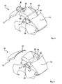
- FIG. 3 As it is in Fig. 3 is shown, then or at the same time the front roof part 22 and the front, lateral roof frame parts 24 separated from the windshield frame 12 and move together with the rear end of the front roof frame parts 24 hinged rear lateral roof frame members 28.
- the rear roof frame parts 28 perform a pivoting movement such from pivoting backwards about their rear-facing pivot axis to the vehicle body, aligning their outsides toward the ground.
- the front roof frame parts 24 are moved by their connection to the rear roof frame members 28 and simultaneously pivoted by the hinge connection between the front roof frame members 24 and the rear roof frame members 28 with respect to the rear roof frame members 28 in a direction opposite to the pivoting direction of the rear side roof frame members 28, so that their undersides the approximate upward undersides of the rear, side roof frame parts 28.
- the rear, side roof frame parts pivot in a direction A clockwise relative to the body, while the front lateral roof frame members 24 in one direction with respect to the rear, side roof frame members 28 turn clockwise.
- connection between the roof frame parts 24, 28 and the roof parts 22, 26 is a hinge.
- Scissors mechanisms are provided, which means that the pivot axes move relative to the roof frame parts or the roof parts.
- the front roof part 22 performs a pivoting movement relative to the front, lateral roof frame parts 24.
- the pivot axis and the hinge point between the front roof part 22 and the front roof frame parts 24 is located at a front end region of the front roof part 22, ie clearly with respect to Center of the front roof part 22 offset forward.
- the rear roof part 26 remains unchanged at the beginning of the pivoting movement of the roof structure 20 in its position relative to the rear roof frame parts 28, ie it performs the pivoting movement, which is indicated by the arrow A, also from.
- the front roof part 22 approaches a position in which it is parallel to the rear roof part 26 in such a way that its outside surface is directed to the inner surface of the rear roof part 26.
- the front roof part thus pivots in a direction B in a clockwise direction with respect to the front roof frame parts 24.
- the rear roof part 26 which has a hinge connection to the rear lateral roof frame parts 28 in a central region of it in the vehicle longitudinal direction, about this axis also performs a rotational movement, which in Fig. 4 indicated by the arrow C.
- the direction C of the pivoting movement is opposite to that of the front roof part 22 with respect to the front roof frame parts 24.
- the front and the rear roof part 22, 26 remain almost parallel to each other, while the front roof frame parts 24 and the rear roof frame parts 28 are folded further on each other and in the rear region of the vehicle, in particular under the boot lid 14, introduced.
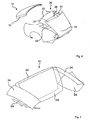
- FIG. 5 A side view of the essential components of the roof structure 20 (as viewed in a direction to the left side of the motor vehicle) is shown in FIG Fig. 5 shown.
- Fig. 5 is indicated by dash-dot lines the closed position of the roof.
- the positions of the roof elements corresponding to an opening state of Fig. 4 are indicated by solid lines.
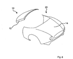
- the roof structure 20 finally reaches the in Fig. 6 shown position in which the front roof part 22 is parallel to the rear roof part 26 and positioned in front of this behind the rear seat (not shown) of the vehicle is introduced.
- the roof frame parts 24, 28 are folded on each other.
- Fig. 7 also shows this final state, ie the fully open roof structure without the boot lid or fender area of the vehicle.
- the boot lid 14 is finally closed, whereby the roof frame parts are hidden under this in its folded state.
- the trunk is accessible without loading assistance.
- the essential aspect of the invention is to provide a fully openable vehicle roof for in particular a two-seat motor vehicle (Roadstar), which requires few components and can be stored by means of which large-scale, rigid roof parts in the rear of the vehicle to open the vehicle roof.
- Roadstar two-seat motor vehicle
Landscapes
- Engineering & Computer Science (AREA)
- Mechanical Engineering (AREA)
- Body Structure For Vehicles (AREA)
Abstract
Description
- Die Erfindung betrifft eine Dachstruktur für ein zu öffnendes starres Kraftfahrzeugdach, mit dem insbesondere ein Personenkraftwagen als offenes Fahrzeug oder als geschlossenes Fahrzeug verwendet werden kann. Insbesondere ist die erfindungsgemäße Dachstruktur für ein zweisitziges Cabriolet anwendbar.
- Aus der
DE 296 22 436 U1 ist ein Kraftfahrzeugdach mit versenkbaren Dachteilen bekannt, das starre, nicht zu öffnende seitliche Dachrahmenteile besitzt. Ein vorderes und ein hinteres Dachteil sind um eine senkrecht zur Fahrzeuglängsebene liegende Achse schwenkbar. - Die
DE 100 21 464 A1 betrifft ebenfalls ein Fahrzeug mit einem zu öffnenden Fahrzeugdach, das karosseriefeste Dachlängsholme besitzt. Ferner ist eine bewegliche Dachteileinrichtung zum wahlweisen Verschließen oder zumindest teilweisem Freigeben der Dachöffnung sowie mit einer sich an das Fahrzeugdach anschließenden Heckscheibe vorgesehen. Die Dachteileinrichtung weist Dachteilelemente auf, die an seitlichen Führungen verschiebbar geführt und beim Öffnen der Dachteileinrichtung in einen hinteren Ablageraum ablegbar sind, wobei sie beispielsweise ziehharmonikaartig gefaltet sind oder rolloartig aufgerollt sind. Die Heckscheibe ist in eine Stellung absenkbar, in der sie aus der Heckscheibenöffnung des Dachrahmens entfernt ist und zumindest teilweise unter einer Kofferraumklappe angeordnet ist. Die Dachteilelemente bzw. Lamellen werden entlang der seitlichen Dachlängsholme und in den Ablageraum in Fahrzeuglängsrichtung verschoben. - Die
DE 42 03 228 C2 betrifft eine ähnliche Konstruktion, bei der ein Faltdach, Lamellendach oder Rollodach in einen heckseitig im Fahrzeug vorgesehenen Stauraum in Fahrzeuglängsrichtung zum Öffnen des Fahrzeugdachs verschoben wird. Die B-Säulen und die C-Säulen des Fahrzeugs bilden zusammen mit seitlichen Dachrahmenteilen und dem hinteren Dachrahmenteil ein Viergelenk, das nach Absenken der Heckscheibe und der hinteren und vorderen Seitenscheiben mittels eines Antriebs nach hinten schwenkbar ist. - Bei dem in der
DE 198 04 990 C1 beschriebenen Cabrioletverdeck für ein Kraftfahrzeug sind eine Vielzahl von miteinander verbundenen Einzellamellen vorgesehen, die in der offenen Stellung in einen Stauraum eingebracht sind. Sie werden aus der geschlossenen Stellung dorthin in Fahrzeuglängsrichtung verschoben, und rolladenartig um eine Verdeckrolle aufgewickelt. Die Dachrahmen und die C-Säulen des Fahrzeugs sind in den hinteren Bereich des Kraftfahrzeugs absenkbar, wobei die vorderen Dachrahmen um eine vertikale Achse in Richtung auf den hinteren Dachrahmen in den Fahrzeuginnenraum schwenkbar sind. Nach dem Verschwenken werden die vorderen und hinteren Dachrahmen zusammen entlang der Innenseite der C-Säule verschoben, so dass weder der vordere Dachrahmen noch der hintere Dachrahmen über die C-Säule hinausragen. Anschließend wird die aus dem Dachrahmen und der C-Säule bestehenden Einheit in die Karosserie des Fahrzeugs versenkt. - Aus der
DE 100 63 152 A1 ist schließlich ein Klappdachwagen bekannt, bei dem ein vorderes Dachteil, das auch seitliche Dachrahmenteile enthält, und ein hinteres Dachteil, das ebenfalls seitliche Dachrahmenteile enthält, um eine senkrecht zur Fahrzeuglängsebene verlaufende Achse zueinander verschwenkbar sind und in einen Stauraum unter einen Heckdeckel eines Kraftfahrzeugs ablegbar sind. - Die gattungsgemäße
EP 1 618 014 B1 beschreibt eine Dachstruktur für ein zu öffnendes starres Kraftfahrzeugdach mit einem vorderen Dachteil und einem hinteren Dachteil. An das vordere Dachteil und das hintere Dachteil schließen sich jeweils seitliche Dachrahmenteile an. Die vorderen und hinteren Dachrahmenteile sind bezüglich einander um eine senkrechte Fahrzeuglängsebene verlaufende Achse schwenkbar und in einer Position, in der ihre Innenseiten zueinander gerichtet sind, ablegbar. Das vordere Dachteil und das hintere Dachteil sind jeweils bezüglich der Dachrahmenteile um eine senkrecht zur Fahrzeuglängsebene verlaufende Achse verschwenkbar. - Der Erfindung liegt die Aufgabe zugrunde, eine Dachstruktur für ein zu öffnendes starres Kraftfahrzeugdach vorzusehen, das vollständig zu öffnen ist und das im offenen Zustand des Fahrzeugdachs wenig Stauraum im Fahrzeugheckbereich beansprucht.
- Diese Aufgabe wird mit einer Dachstruktur mit den Merkmalen des Anspruchs 1 gelöst. Bevorzugte Ausführungsformen sind in den abhängigen Ansprüchen angegeben.
- Die Ausdrücke "vorne", "hinten", "seitlich" beziehen sich dabei auf eine Orientierung in Vorwärtsfahrtrichtung des Kraftfahrzeugs. Entsprechend bezeichnet die Fahrzeuglängsrichtung des Kraftfahrzeugs diejenige Richtung, in der das Fahrzeug bei Geradeausfahrt und Vorwärtsfahrt fährt. Ferner ist die "Innenseite" von Dachelementen diejenige Seite, die der Fahrgastzelle zugewandt ist, wenn das Dach geschlossen ist.
- Der Erfindung liegt der Gedanke zugrunde, eine Öffnungsmöglichkeit für ein starres Kraftfahrzeugdach dadurch vorzusehen, dass die Dachteile ebenso wie die Dachrahmenteile verschwenkt werden und zwar um jeweils Achsen, die senkrecht zur Fahrzeuglängsebene liegen. Dadurch ist es möglich, eine Verschiebung der Dachteile entlang der Dachrahmenteile in Fahrzeuglängsrichtung zu vermeiden. Somit können verhältnismäßig großflächige Dachteile verwendet werden, was zu einem ansprechenden Erscheinungsbild beiträgt. Dadurch, dass gleichzeitig sowohl die Dachrahmenteile bezüglich einander verschwenkbar sind als auch die Dachteile jeweils bezüglich der einzelnen Dachrahmenteile verschwenkbar sind, kann überdies das Fahrzeug vollständig geöffnet werden, ohne dass Dachrahmenteile die vollständige Öffnung des Fahrzeugdachs behindern.
- Nachfolgend wird die Erfindung beispielhaft anhand der beigefügten Figuren beschrieben, in denen:
-
Fig. 1 den Heckbereich eines Fahrzeugs mit geschlossenem Dach in perspektivischer Ansicht zeigt; -
Fig. 2 den Heckbereich des Fahrzeugs am Anfang der Öffnungsbewegung des Dachs zeigt; -
Fig. 3 einen weiter fortgeschrittenen Zustand der Öffnungsbewegung des Dachs zeigt; -
Fig. 4 einen noch weiter fortgeschrittenen Zustand der Öffnungsbewegung der Dachstruktur zeigt; -
Fig. 5 eine seitliche Ansicht der Kinematik der erfindungsgemäßen Dachstruktur zeigt; -
Fig. 6 den Heckbereich des Fahrzeugs bei nahezu vollständig geöffnetem Dach in perspektivischer Ansicht zeigt; -
Fig. 7 die Endstellung der Dachstruktur bei geöffnetem Fahrzeugdach zeigt, wobei der Heckdeckel sowie die Kotflügelbereiche des Fahrzeugs weggelassen sind; und -
Fig. 8 das Fahrzeug mit der erfindungsgemäßen Dachstruktur bei offenem Dach zeigt. -
Fig. 1 zeigt in perspektivischer Ansicht eine Ausführungsform der erfindungsgemäßen Dachstruktur für ein zu öffnendes starres Kraftfahrzeugdach.Fig. 1 zeigt den Heckbereich 10 eines Fahrzeugs. Die Dachstruktur 20, die an einen Windschutzscheibenrahmen 12 angrenzend angeordnet ist, enthält ein vorderes Dachteil 22, vordere seitliche Dachrahmenteile 24, ein hinteres Dachteil 26 sowie hintere, seitliche Dachrahmenteile 28. Das hintere Dachteil 26 grenzt an seiner Vorderkante an das vordere Dachteil 22 an, das wiederum an seiner vorderen Kante an den Windschutzscheibenrahmen 12 anstößt, wenn das Fahrzeugdach geschlossen ist. Das hintere Dachteil 26 grenzt mit seinem hinteren Rand an den Heckdeckel 14 des Kraftfahrzeugs an. Die seitlichen Dachrahmenteile 24, 28 sind jeweils links und rechts (betrachtet in Fahrzeugvorwärtsfahrtrichtung) des vorderen Dachteils 22 beziehungsweise des hinteren Dachteils 26 angeordnet, wobei sich die vorderen, seitlichen Dachrahmenteile 24 in Längsrichtung soweit wie das vordere Dachteil 22 und die hinteren seitlichen Dachrahmenteile 28 in Fahrzeuglängsrichtung soweit wie das hintere Dachteil 26 erstrecken. - Das vordere Dachteil 22 und das hintere Dachteil 26 sind jeweils einstückig gestaltet und als starre Bauteile gebildet (Hardtop). In das hintere Dachteil 26 ist eine Heckscheibe integriert beziehungsweise es wird durch die Heckscheibe gebildet. Nach Bedarf kann in das vordere Dachteil 22 beispielsweise ein Sonnendach oder ähnliches integriert sein.
- Zum Öffnen der Dachstruktur wird zunächst, wie es in
Fig. 2 gezeigt ist, der Heckdeckel 14 derart aufgeschwenkt, dass sich sein frontseitiger Endbereich anhebt und somit Stauraum für die Dachstruktur 20 freigibt beziehungsweise das Einbringen der Dachstruktur in den Bereich unter den Heckdeckel 14 ermöglicht. Die Schwenkachse liegt beispielsweise am heckseitigen Abschluss des Heckdeckels 14. - Wie es in
Fig. 3 dargestellt ist, werden anschließend oder zeitgleich das vordere Dachteil 22 sowie die vorderen, seitlichen Dachrahmenteile 24 vom Windschutzscheibenrahmen 12 getrennt und bewegen sich zusammen mit den am heckseitigen Ende der vorderen Dachrahmenteile 24 angelenkten hinteren, seitlichen Dachrahmenteilen 28. Die hinteren Dachrahmenteile 28 führen eine Schwenkbewegung derart aus, dass sie um ihre heckseitigen Anlenkachse zur Fahrzeugkarosserie nach hinten schwenken, wodurch sie mit ihren Außenseiten Richtung Boden ausgerichtet werden. Die vorderen Dachrahmenteile 24 werden durch ihre Verbindung zu den hinteren Dachrahmenteilen 28 mitbewegt und gleichzeitig durch die Scharnierverbindung zwischen den vorderen Dachrahmenteilen 24 und den hinteren Dachrahmenteilen 28 bezüglich der hinteren Dachrahmenteile 28 in einer Richtung entgegengesetzt zur Schwenkrichtung der hinteren seitlichen Dachrahmenteile 28 verschwenkt, so dass ihre Unterseiten sich den nach oben gerichteten Unterseiten der hinteren, seitlichen Dachrahmenteile 28 annähern. Betrachtet man das Fahrzeug in einer seitlichen Ansicht auf die linke Außenseite des Fahrzeugs, so schwenken die hinteren, seitlichen Dachrahmenteile in einer Richtung A im Uhrzeigersinn bezüglich der Karosserie, während die vorderen, seitlichen Dachrahmenteile 24 bezüglich der hinteren, seitlichen Dachrahmenteile 28 in einer Richtung entgegen dem Uhrzeigersinn schwenken. - Im einfachsten Fall ist die Verbindung zwischen den Dachrahmenteilen 24, 28 und den Dachteilen 22, 26 ein Scharnier. Alternativ können jedoch auch z.B. Scherenmechanismen vorgesehen werden, was bedeutet, dass die Schwenkachsen relativ zu den Dachrahmenteilen bzw. den Dachteilen wandern.
- Gleichzeitig führt das vordere Dachteil 22 eine Schwenkbewegung relativ zu den vorderen, seitlichen Dachrahmenteilen 24 aus. In der dargestellten Ausführungsform liegt die Schwenkachse sowie der Scharnierpunkt zwischen dem vorderen Dachteil 22 und den vorderen Dachrahmenteilen 24 an einem vorderen Endbereich des vorderen Dachteils 22, d.h. deutlich bezüglich der Mitte des vorderen Dachteils 22 nach vorne versetzt. Das hintere Dachteil 26 bleibt am Anfang der Schwenkbewegung der Dachstruktur 20 in seiner Lage relativ zu den hinteren Dachrahmenteilen 28 unverändert, d.h. es führt die Schwenkbewegung, die durch den Pfeil A angegeben ist, ebenfalls aus. Durch diese Schwenkbewegung nähert sich das vordere Dachteil 22 einer Position an, in der es parallel zum hinteren Dachteil 26 wird und zwar derart, dass seine außenseitige Fläche auf die innenliegende Fläche des hinteren Dachteils 26 gerichtet ist. Betrachtet aus einer Seitenansicht auf die linke Seite des Kraftfahrzeugs, schwenkt das vordere Dachteil somit in einer Richtung B im Uhrzeigersinn bezüglich der vorderen Dachrahmenteile 24.
- Im weiteren Verlauf der Öffnungsbewegung der Dachstruktur 20, der in
Fig. 4 dargestellt ist, führt das hintere Dachteil 26, das eine Scharnierverbindung zu den hinteren seitlichen Dachrahmenteilen 28 in einem zentralen Bereich von ihm in Fahrzeuglängsrichtung aufweist, um diese Achse ebenfalls eine Drehbewegung aus, die inFig. 4 mit dem Pfeil C angegeben ist. Die Richtung C der Schwenkbewegung ist dabei entgegengesetzt zu derjenigen des vorderen Dachteils 22 bezüglich der vorderen Dachrahmenteile 24. Betrachtet in einer Seitenansicht auf die linke Seite des Kraftfahrzeugs bedeutet dies, dass das hintere Dachteil 26 bezüglich der hinteren, seitlichen Dachrahmenteile 28 in einer Richtung entgegen dem Uhrzeigersinn verdreht wird. Dadurch bleiben das vordere und das hintere Dachteil 22, 26 nahezu parallel zueinander, während die vorderen Dachrahmenteile 24 und die hinteren Dachrahmenteile 28 weiter aufeinander gefaltet werden und in den Heckbereich des Fahrzeugs, insbesondere unter den Heckdeckel 14, eingebracht werden. - Eine Seitenansicht auf die wesentlichen Bauteile der Dachstruktur 20 (betrachtet in einer Richtung auf die linke Seite des Kraftfahrzeugs) ist in
Fig. 5 dargestellt. InFig. 5 ist mit Strich-Punkt-Linien die geschlossene Position des Dachs angedeutet. Die Positionen der Dachelemente entsprechend einem Öffnungszustand vonFig. 4 sind mit durchgezogenen Linien angegeben. - Durch weiter fortgesetzte Öffnungsbewegungen erreicht die Dachstruktur 20 schließlich die in
Fig. 6 dargestellte Position, in der das vordere Dachteil 22 parallel zu dem hinteren Dachteil 26 und vor diesem positioniert hinter der Rückbank (nicht dargestellt) des Fahrzeugs eingebracht ist. Die Dachrahmenteile 24, 28 sind dabei aufeinander gefaltet.Fig. 7 zeigt ebenfalls diesen Endzustand, d.h. das vollständig geöffnete Dachstruktur ohne den Heckdeckel beziehungsweise Kotflügelbereich des Fahrzeugs. - Zum Abschluss der Öffnungsbewegung wird schließlich der Heckdeckel 14 geschlossen, wodurch die Dachrahmenteile unter diesem in ihrem gefalteten Zustand verborgen werden. Der Kofferraum ist ohne Beladehilfe erreichbar.
- Die Schließbewegung der Dachstruktur verläuft in umgekehrter Reihenfolge.
- Der wesentliche Aspekt der Erfindung liegt darin, ein vollständig zu öffnendes Fahrzeugdach für insbesondere ein zweisitziges Kraftfahrzeug (Roadstar) vorzusehen, das wenig Bauteile erfordert und mit Hilfe dessen großflächige, starre Dachteile in den Heckbereich des Fahrzeugs zum Öffnen des Fahrzeugdachs abgelegt werden können.
-
- 10
- Heckbereich
- 12
- Windschutzscheibenrahmen
- 14
- Heckdeckel
- 20
- Dachstruktur
- 22
- vorderes Dachteil
- 24
- vorderes, seitliches Dachrahmenteil
- 25
- Scharnierpunkt zwischen vorderem Dachteil und vorderem Dachrahmenteilen
- 26
- hinteres Dachteil
- 28
- hinteres, seitliches Dachrahmenteil
- 29
- Scharnierpunkt zwischen hinterem Dachteil und hinteren Dachrahmenteilen
Claims (7)
- Dachstruktur (20) für ein zu öffnendes starres Kraftfahrzeugdach, enthaltend ein vorderes Dachteil (22), an das vordere Dachteil (22) sich seitlich anschließende vordere Dachrahmenteile (24), ein hinteres Dachteil (26) und an das hintere Dachteil (26) sich seitlich anschließende hintere Dachrahmenteile (28), wobei die vorderen und hinteren Dachrahmenteile (24, 28) bezüglich einander um eine senkrecht zur Fahrzeuglängsebene verlaufende Achse schwenkbar und in eine Position, in der ihre Innenseiten zueinander gerichtet sind, ablegbar sind und das vordere Dachteil (22) bezüglich der vorderen Dachrahmenteile (24) und das hintere Dachteil (26) bezüglich der hinteren Dachrahmenteile (28) um jeweils eine senkrecht zur Fahrzeuglängsebene verlaufende Achse verschwenkbar ist, wobei das vordere Dachteil (22) bezüglich der vorderen Dachrahmenteile (24) um eine im Wesentlichen senkrecht zur Fahrzeuglängsrichtung liegende Achse (25) verschwenkbar ist, die mit den Dachrahmenteilen und dem Dachteil mitbeweglich ist und in einem vorderen Bereich der vorderen Dachrahmenteile und des vorderen Dachteils in Fahrzeuglängsrichtung liegt.
- Dachstruktur (20) nach Anspruch 1, dadurch gekennzeichnet, dass in der offenen Position der Dachstruktur das vordere Dachteil (22) und das hintere Dachteil (26) in im Wesentlichen vertikaler Position hinter einem Fahrgastraum des Fahrzeugs positioniert sind.
- Dachstruktur (20) nach Anspruch 2, dadurch gekennzeichnet, dass in der offenen Position der Dachstruktur das vordere Dachteil (22) in Fahrzeugvorwärtsfahrtrichtung vor dem hinteren Dachteil (26) liegt und die Unterseite des hinteren Dachteils (26) der Oberseite des vorderen Dachteils (22) zugewandt ist.
- Dachstruktur (20) nach einem der vorhergehenden Ansprüche, dadurch gekennzeichnet, dass das hintere Dachteil (26) bezüglich der hinteren Dachrahmenteile (28) um eine im Wesentlichen senkrecht zur Fahrzeuglängsrichtung liegende Achse (29) verschwenkbar ist, die mit den Dachrahmenteilen und dem Dachteil mitbeweglich ist und in einem mittleren Bereich der hinteren Dachrahmenteile und des hinteren Dachteils in Fahrzeuglängsrichtung liegt.
- Dachstruktur (20) nach einem der vorhergehenden Ansprüche, dadurch gekennzeichnet, dass die Schwenkrichtung des vorderen Dachteils (22) bezüglich der vorderen Dachrahmenteile (24) entgegengesetzt zur Schwenkrichtung des hinteren Dachteils (26) bezüglich der hinteren Dachrahmenteile (28) ist.
- Dachstruktur (20) nach einem der vorhergehenden Ansprüche, dadurch gekennzeichnet, dass in der offenen Position der Dachstruktur die Dachrahmenteile (24, 28) mit ihren Unterseiten aufeinander gefaltet und in den Heckbereich des Fahrzeugs unter einer Heckklappe (14) ablegbar sind.
- Dachstruktur (20) nach einem der vorhergehenden Ansprüche, dadurch gekennzeichnet, dass das vordere Dachteil (22) und das hintere Dachteil (26) jeweils einstückige Dachelemente sind.
Applications Claiming Priority (2)
| Application Number | Priority Date | Filing Date | Title |
|---|---|---|---|
| DE102004018606A DE102004018606B4 (de) | 2004-04-16 | 2004-04-16 | Dachstruktur für ein zu öffnendes starres Kraftfahrzeugdach |
| PCT/DE2005/000593 WO2005100065A1 (de) | 2004-04-16 | 2005-04-04 | Dachstruktur für ein zu öffnendes starres kraftfahrzeugdach |
Publications (2)
| Publication Number | Publication Date |
|---|---|
| EP1744920A1 EP1744920A1 (de) | 2007-01-24 |
| EP1744920B1 true EP1744920B1 (de) | 2011-01-19 |
Family
ID=34967143
Family Applications (1)
| Application Number | Title | Priority Date | Filing Date |
|---|---|---|---|
| EP05740727A Expired - Lifetime EP1744920B1 (de) | 2004-04-16 | 2005-04-04 | Dachstruktur für ein zu öffnendes starres kraftfahrzeugdach |
Country Status (4)
| Country | Link |
|---|---|
| US (1) | US7758101B2 (de) |
| EP (1) | EP1744920B1 (de) |
| DE (2) | DE102004018606B4 (de) |
| WO (1) | WO2005100065A1 (de) |
Families Citing this family (8)
| Publication number | Priority date | Publication date | Assignee | Title |
|---|---|---|---|---|
| DE102004028467A1 (de) * | 2004-06-11 | 2005-12-29 | Wilhelm Karmann Gmbh | Cabriolet-Fahrzeug |
| DE102006007635B4 (de) * | 2006-02-18 | 2010-04-08 | Magna Car Top Systems Gmbh | Dach für einen Personenkraftwagen |
| DE102006024301A1 (de) * | 2006-05-24 | 2007-11-29 | Dr.Ing.H.C. F. Porsche Ag | Fahrzeug mit einem Faltverdeck |
| FR2911090B1 (fr) * | 2007-01-10 | 2012-03-30 | Heuliez | Toit mobile a encombrement limite. |
| FR2911091B1 (fr) * | 2007-01-10 | 2011-07-01 | Heuliez | Toit mobile a encombrement limite |
| US7845704B2 (en) * | 2007-04-18 | 2010-12-07 | Magna Car Top Systems | Transparent outer panel for a retractable hardtop |
| US10029548B1 (en) * | 2015-10-07 | 2018-07-24 | Mark A. Stadnyk | Adjustable and removable hard top roof system |
| WO2023173112A1 (en) * | 2022-03-11 | 2023-09-14 | Tuga-Global, Inc. | Expanding length vehicle chassis |
Family Cites Families (23)
| Publication number | Priority date | Publication date | Assignee | Title |
|---|---|---|---|---|
| US2768025A (en) | 1952-11-26 | 1956-10-23 | Ford Motor Co | Retractible rigid automobile top |
| US5078447A (en) | 1990-01-12 | 1992-01-07 | C&C Incorporated | Multi-position retractable vehicle roof |
| DE4038074C1 (en) | 1990-11-29 | 1991-10-31 | Mercedes-Benz Aktiengesellschaft, 7000 Stuttgart, De | Roof for cabriolet vehicle - has roof pivoting on two support link rods hinged on lateral supports |
| DE4203228C2 (de) * | 1992-02-05 | 1994-06-30 | Webasto Karosseriesysteme | Fahrzeugdach |
| DE4445580C1 (de) | 1994-12-20 | 1995-12-21 | Daimler Benz Ag | Hardtop-Fahrzeug |
| DE29620492U1 (de) * | 1996-11-25 | 1998-03-26 | Wilhelm Karmann GmbH, 49084 Osnabrück | Cabriolet-Fahrzeug |
| DE29622436U1 (de) | 1996-12-28 | 1998-01-08 | Wilhelm Karmann GmbH, 49084 Osnabrück | Kraftfahrzeug |
| DE19804990C1 (de) * | 1998-02-07 | 1999-05-06 | Daimler Chrysler Ag | Cabrioletverdeck für ein Kraftfahrzeug |
| FR2778610B1 (fr) | 1998-05-12 | 2000-08-04 | France Design | Toit repliable en trois elements pour vehicule decouvrable |
| US6439642B2 (en) | 1998-05-25 | 2002-08-27 | Dura Convertable Gmbh | Retractable hard top for passenger cars |
| DE59800392D1 (de) * | 1998-05-25 | 2001-01-25 | Dura Convertible Systems Gmbh | Versenkbares Fahrzeugdach für Personenkraftwagen |
| FR2805218B1 (fr) | 2000-02-21 | 2002-07-19 | France Design | Toit escamotable dans le coffre arriere d'un vehicule, ce toit comportant une lunette arriere pivotante |
| DE10021464B4 (de) | 2000-05-04 | 2007-09-06 | Webasto Ag | Fahrzeug mit einem zu öffnenden Fahrzeugdach |
| FI110418B (fi) * | 2000-05-05 | 2003-01-31 | Valmet Automotive Oy | Avoauto |
| DE10107078B4 (de) * | 2001-02-13 | 2013-11-14 | Webasto Ag | Umwandelbares Fahrzeugdach |
| DE10116709C2 (de) | 2001-04-04 | 2003-03-27 | Edscha Cabrio Dachsys Gmbh | Klappverdeck mit Heckscheibensteuerung |
| US6866324B2 (en) | 2002-02-25 | 2005-03-15 | Ssr Roofing Systems, L.L.C. | Folding hardtop with rear window articulation |
| DE20313456U1 (de) | 2002-10-17 | 2003-11-13 | Wilhelm Karmann GmbH, 49084 Osnabrück | Cabriolet-Fahrzeug |
| DE10248348A1 (de) * | 2002-10-17 | 2004-05-06 | Wilhelm Karmann Gmbh | Cabriolet-Fahrzeug |
| AU2003281943A1 (en) | 2002-10-17 | 2004-05-13 | Wilhelm Karmann Gmbh | Cabriolet vehicle |
| FR2854352B1 (fr) * | 2003-04-29 | 2005-07-01 | France Design | Toit escamotable de vehicule |
| US7360828B2 (en) * | 2003-07-16 | 2008-04-22 | Société Européenne de Brevet Automobiles | Sliding roof system with stackable panels and vehicle equipped therewith |
| US7063371B2 (en) * | 2004-03-12 | 2006-06-20 | Asc Incorporated | Convertible hardtop roof |
-
2004
- 2004-04-16 DE DE102004018606A patent/DE102004018606B4/de not_active Expired - Fee Related
-
2005
- 2005-04-04 DE DE502005008187T patent/DE502005008187D1/de not_active Expired - Lifetime
- 2005-04-04 WO PCT/DE2005/000593 patent/WO2005100065A1/de not_active Ceased
- 2005-04-04 US US11/578,616 patent/US7758101B2/en not_active Expired - Fee Related
- 2005-04-04 EP EP05740727A patent/EP1744920B1/de not_active Expired - Lifetime
Also Published As
| Publication number | Publication date |
|---|---|
| DE102004018606A1 (de) | 2005-11-03 |
| EP1744920A1 (de) | 2007-01-24 |
| US20080030044A1 (en) | 2008-02-07 |
| DE502005008187D1 (de) | 2011-06-09 |
| US7758101B2 (en) | 2010-07-20 |
| DE102004018606B4 (de) | 2011-06-09 |
| WO2005100065A1 (de) | 2005-10-27 |
Similar Documents
| Publication | Publication Date | Title |
|---|---|---|
| EP0826537B1 (de) | Dachkonstruktion für ein Kraftfahrzeug, insbesondere für einen Personenkraftwagen | |
| EP1245419B1 (de) | Cabriolet-Fahrzeug mit einem Windschott | |
| DE10152944B4 (de) | Verdeck für ein Cabriolet-Fahrzeug | |
| EP0992384B1 (de) | Personenkraftwagen mit einem verschwenkbaren Fliessheckscheibenrahmen | |
| DE19926474B4 (de) | Kraftfahrzeug mit einem absenkbaren Verdeckkasten | |
| EP1554147B1 (de) | Bewegliches mehrfach geteiltes dach für ein kraftfahrzeug | |
| EP1331122B1 (de) | Kraftfahrzeug mit versenkbarem Hardtop | |
| DE10218241C1 (de) | Verdeck für ein Cabrioletfahrzeug | |
| EP1971501A1 (de) | Klappverdeck für einen kraftwagen | |
| DE102004018606B4 (de) | Dachstruktur für ein zu öffnendes starres Kraftfahrzeugdach | |
| EP3224074B1 (de) | Kraftfahrzeug | |
| DE102007004180B4 (de) | Verstellbares Fahrzeugdach | |
| WO2008061578A1 (de) | Verdecksystem für ein gabriolet-fahrzeug | |
| DE102006050874B4 (de) | Öffenbares Fahrzeugdach mit Betätigungseinrichtung für ein Dachelement | |
| DE10120359C2 (de) | Fahrzeug mit einem zu öffnenden Verdeck | |
| DE102004055404A1 (de) | Fahrzeugdach | |
| DE10327355B4 (de) | Cabriolet-Verdeckanordnung | |
| DE10204663A1 (de) | Fahrzeug mit öffenbarem Dach | |
| DE102009037786B4 (de) | Klappdach für PKW | |
| DE10248857B4 (de) | Verstellbares Fahrzeugdach | |
| DE10155887A1 (de) | Kabriolett | |
| DE102004040889B4 (de) | Cabriolet-Fahrzeug mit zumindest zwei Lenkern zur Dachbewegung | |
| DE10308063A1 (de) | Kraftfahrzeug | |
| DE102005041023A1 (de) | Karosseriestruktur für ein Fahrzeug | |
| DE202021100802U1 (de) | Kombi-Cabriolet |
Legal Events
| Date | Code | Title | Description |
|---|---|---|---|
| PUAI | Public reference made under article 153(3) epc to a published international application that has entered the european phase |
Free format text: ORIGINAL CODE: 0009012 |
|
| 17P | Request for examination filed |
Effective date: 20061116 |
|
| AK | Designated contracting states |
Kind code of ref document: A1 Designated state(s): DE FR GB IT |
|
| RIN1 | Information on inventor provided before grant (corrected) |
Inventor name: SCHROEDER, MICHAEL |
|
| DAX | Request for extension of the european patent (deleted) | ||
| RBV | Designated contracting states (corrected) |
Designated state(s): DE FR GB IT |
|
| 17Q | First examination report despatched |
Effective date: 20081211 |
|
| GRAP | Despatch of communication of intention to grant a patent |
Free format text: ORIGINAL CODE: EPIDOSNIGR1 |
|
| GRAS | Grant fee paid |
Free format text: ORIGINAL CODE: EPIDOSNIGR3 |
|
| GRAA | (expected) grant |
Free format text: ORIGINAL CODE: 0009210 |
|
| AK | Designated contracting states |
Kind code of ref document: B1 Designated state(s): DE FR GB IT |
|
| REG | Reference to a national code |
Ref country code: GB Ref legal event code: FG4D Free format text: NOT ENGLISH |
|
| 29U | Proceedings interrupted after grant according to rule 142 epc |
Effective date: 20090629 |
|
| REF | Corresponds to: |
Ref document number: 502005008187 Country of ref document: DE Date of ref document: 20091105 Kind code of ref document: P |
|
| PUAC | Information related to the publication of a b1 document modified or deleted |
Free format text: ORIGINAL CODE: 0009299EPPU |
|
| DB1 | B1 document deleted | ||
| 19W | Proceedings resumed before grant after interruption of proceedings |
Effective date: 20101201 |
|
| GRAA | (expected) grant |
Free format text: ORIGINAL CODE: 0009210 |
|
| AK | Designated contracting states |
Kind code of ref document: B1 Designated state(s): DE FR GB IT |
|
| REG | Reference to a national code |
Ref country code: GB Ref legal event code: FG4D Free format text: NOT ENGLISH |
|
| REF | Corresponds to: |
Ref document number: 502005008187 Country of ref document: DE Date of ref document: 20110609 Kind code of ref document: P |
|
| REG | Reference to a national code |
Ref country code: DE Ref legal event code: R096 Ref document number: 502005008187 Country of ref document: DE Effective date: 20110609 |
|
| PGFP | Annual fee paid to national office [announced via postgrant information from national office to epo] |
Ref country code: IT Payment date: 20110429 Year of fee payment: 7 |
|
| PLBE | No opposition filed within time limit |
Free format text: ORIGINAL CODE: 0009261 |
|
| STAA | Information on the status of an ep patent application or granted ep patent |
Free format text: STATUS: NO OPPOSITION FILED WITHIN TIME LIMIT |
|
| 26N | No opposition filed |
Effective date: 20111020 |
|
| REG | Reference to a national code |
Ref country code: DE Ref legal event code: R097 Ref document number: 502005008187 Country of ref document: DE Effective date: 20111020 |
|
| PG25 | Lapsed in a contracting state [announced via postgrant information from national office to epo] |
Ref country code: IT Free format text: LAPSE BECAUSE OF NON-PAYMENT OF DUE FEES Effective date: 20120404 |
|
| REG | Reference to a national code |
Ref country code: DE Ref legal event code: R082 Ref document number: 502005008187 Country of ref document: DE Representative=s name: KRONTHALER, SCHMIDT & COLL. PATENTANWALTSKANZL, DE |
|
| REG | Reference to a national code |
Ref country code: GB Ref legal event code: 732E Free format text: REGISTERED BETWEEN 20131114 AND 20131120 |
|
| REG | Reference to a national code |
Ref country code: FR Ref legal event code: TP Owner name: VALMET AUTOMOTIVE OY, FI Effective date: 20131209 |
|
| REG | Reference to a national code |
Ref country code: DE Ref legal event code: R082 Ref document number: 502005008187 Country of ref document: DE Representative=s name: KRONTHALER, SCHMIDT & COLL. PATENTANWALTSKANZL, DE Effective date: 20131202 Ref country code: DE Ref legal event code: R081 Ref document number: 502005008187 Country of ref document: DE Owner name: VALMET AUTOMOTIVE OY, FI Free format text: FORMER OWNER: WILHELM KARMANN GMBH, 49084 OSNABRUECK, DE Effective date: 20131202 |
|
| REG | Reference to a national code |
Ref country code: FR Ref legal event code: PLFP Year of fee payment: 12 |
|
| PGFP | Annual fee paid to national office [announced via postgrant information from national office to epo] |
Ref country code: GB Payment date: 20160628 Year of fee payment: 12 Ref country code: DE Payment date: 20160622 Year of fee payment: 12 |
|
| PGFP | Annual fee paid to national office [announced via postgrant information from national office to epo] |
Ref country code: FR Payment date: 20160621 Year of fee payment: 12 |
|
| REG | Reference to a national code |
Ref country code: DE Ref legal event code: R119 Ref document number: 502005008187 Country of ref document: DE |
|
| GBPC | Gb: european patent ceased through non-payment of renewal fee |
Effective date: 20170404 |
|
| REG | Reference to a national code |
Ref country code: FR Ref legal event code: ST Effective date: 20171229 |
|
| PG25 | Lapsed in a contracting state [announced via postgrant information from national office to epo] |
Ref country code: DE Free format text: LAPSE BECAUSE OF NON-PAYMENT OF DUE FEES Effective date: 20171103 Ref country code: FR Free format text: LAPSE BECAUSE OF NON-PAYMENT OF DUE FEES Effective date: 20170502 |
|
| PG25 | Lapsed in a contracting state [announced via postgrant information from national office to epo] |
Ref country code: GB Free format text: LAPSE BECAUSE OF NON-PAYMENT OF DUE FEES Effective date: 20170404 |