EP1746065B1 - Installation de traitement de surface avec dispositif de levage, et dispositif de levage avec galets de guidage non-cylindriques - Google Patents
Installation de traitement de surface avec dispositif de levage, et dispositif de levage avec galets de guidage non-cylindriques Download PDFInfo
- Publication number
- EP1746065B1 EP1746065B1 EP05015921A EP05015921A EP1746065B1 EP 1746065 B1 EP1746065 B1 EP 1746065B1 EP 05015921 A EP05015921 A EP 05015921A EP 05015921 A EP05015921 A EP 05015921A EP 1746065 B1 EP1746065 B1 EP 1746065B1
- Authority
- EP
- European Patent Office
- Prior art keywords
- guiding
- surface treatment
- lifting
- installation according
- treatment installation
- Prior art date
- Legal status (The legal status is an assumption and is not a legal conclusion. Google has not performed a legal analysis and makes no representation as to the accuracy of the status listed.)
- Expired - Lifetime
Links
Images



Classifications
-
- B—PERFORMING OPERATIONS; TRANSPORTING
- B66—HOISTING; LIFTING; HAULING
- B66F—HOISTING, LIFTING, HAULING OR PUSHING, NOT OTHERWISE PROVIDED FOR, e.g. DEVICES WHICH APPLY A LIFTING OR PUSHING FORCE DIRECTLY TO THE SURFACE OF A LOAD
- B66F7/00—Lifting frames, e.g. for lifting vehicles; Platform lifts
- B66F7/02—Lifting frames, e.g. for lifting vehicles; Platform lifts with platforms suspended from ropes, cables, or chains or screws and movable along pillars
-
- B—PERFORMING OPERATIONS; TRANSPORTING
- B66—HOISTING; LIFTING; HAULING
- B66F—HOISTING, LIFTING, HAULING OR PUSHING, NOT OTHERWISE PROVIDED FOR, e.g. DEVICES WHICH APPLY A LIFTING OR PUSHING FORCE DIRECTLY TO THE SURFACE OF A LOAD
- B66F7/00—Lifting frames, e.g. for lifting vehicles; Platform lifts
- B66F7/28—Constructional details, e.g. end stops, pivoting supporting members, sliding runners adjustable to load dimensions
Definitions
- Such surface treatment equipment serves to treat surfaces of articles in a variety of ways, eg, by applying paints and other coatings. Frequently such systems contain several individual treatment stations for different treatment steps, eg preparation, painting and drying.
- the objects to be treated which may be, for example, motor vehicle bodies or other sheet metal parts, are used for this purpose Assistance of a conveyor system promoted from treatment station to treatment station.
- Known in the art lifting stations for the vertical transfer of objects in surface treatment plants are provided, have a lifting, which is guided by means of cylindrical guide rollers in the vertical direction (stroke direction).
- the support structures of the known lifting stations contain for this purpose vertical guide stand with a rectangular cross-section, against which rest the guide rollers of the lifting.
- a total of four guide rollers namely in an upper vertical position of the lifting a rear and a lateral guide roller and in a lower vertical position, a front and a side guide roller.
- lifting stations very high demands are made on the reliability. This is due to the fact that the objects are conveyed in succession through the individual treatment stations. A failure of a single lifting station therefore generally entails the shutdown of the entire surface treatment plant. Furthermore, lifting stations must be designed so that contamination of the surfaces to be treated can be avoided. Going out such contamination, for example, of lubricants that are used for lubrication of moving parts of the lifting station.
- FIG. 1 shows the EP 1 468 957 A2 a column lifter for vehicle bodies according to the preamble of claim 1 with a guide stand and a lifting carriage arranged movably thereon, wherein the guide stand is formed by a double frame and the lifting carriage is guided on this via a plurality of guide rollers.
- the US 6,571,970 B1 shows a monorail conveyor carriage with a telescopic mast.
- the telescopic mast has a plurality of hollow profiles, which are arranged one inside the other, with the help of non-cylindrical guide rollers, which cooperate with attached to the hollow profiles guide rods, the inner hollow profiles are extendable.
- the JP 11 035162 A shows a movable stacker for paper with only one guide column, which has a square cross-section. A load arm pair for paper pallets is guided over double-cone shaped guide rollers on the guide column.
- non-cylindrical guide rollers has the advantage that it is possible to achieve guidance of the lifting carriage on the support structure with fewer guide rollers than was hitherto known in the prior art.
- Radial direction is called the direction perpendicular to the axis of rotation of the guide rollers. While in the known lifting stations a guide in two different directions always required two guide rollers, can be achieved with the inventive design of the guide rollers the same effect with only a leadership role. The total number of required guide rollers can be reduced in this way and possibly even halved. Correspondingly smaller are the weight and the complexity of the lifting carriage, which has a favorable effect on the manufacturing costs and maintenance.
- Particularly simple and low maintenance is a drive by means of a traction means for raising and lowering the lifting carriage, which connects the lifting carriage with a drive motor. Since it is generally unfavorable to arrange the drive motor at the upper end of the lifting station, the traction means via a at the top of the lifting station be arranged guided pulley. The drive motor can then be arranged further down and in particular in the vicinity of the lower end of the lifting station. This is advantageous in that the drive motor is better accessible for maintenance.
- the drive motor is separated from that of the guide posts by a protective wall. This facilitates the maintenance work on the drive motor.
- the wall is then to be provided with openings through which the traction means is guided through the protective wall.
- a deflection roller Between the guide posts and the openings in the protective wall is a deflection roller, which deflects the traction means.
- the shape of the at least one guide roller can be described by rotation of a curved radial contour about an axis of rotation of the at least one guide roller.
- This radial contour can for example be circular arc, parabolic, hyperbolic or defined by any other curved curve.
- the at least one guide roller is to abut along a line on the guide stand, then its cross-section - or more precisely its portion facing the guide roller - must have substantially the same shape as the radial contour. If, on the other hand, it suffices that the at least one leadership role in the area of at least two points is applied to the guide stand, so the cross section and the radial contour can also be shaped differently.
- the cross section of the guide post on which the at least one guide roller bears is circular.
- Guide stand with circular cross-section can be inexpensively made of steel pipes and also have the advantage that can be achieved connection stiff constructions with relatively little use of materials.
- the entire support structure can thereby be substantially slimmer overall and possibly realized with fewer stiffening elements than is possible with the use of rectangular profiles.
- the use of round tubes also has the advantage that dirt is less easily deposited and also easier to remove.
- guide rollers of non-cylindrical shape do not necessarily have to have a curved radial contour.
- a guide roller which has at least one conical section, also achieve a deviating from a radial direction guide.
- guide rollers which have a cylindrical section, followed by a kind of flange, which may be conical, but also not konisch.
- sliding bearing guide rollers By using sliding bearing guide rollers, a further reduction of the maintenance effort is possible.
- sliding bearing guide rollers have the advantage that they can hardly run out of lubricant spatter. Therefore, otherwise required complex protection and cleaning measures may be omitted.
- the at least one guide roller may have a bearing on the guide stand rolling surface, which is made of a plastic. This is advantageous in particular with regard to a low weight of the lifting carriage.
- pulling means for example, chains made of steel or plastic or belts made of textiles, plastics or steel into consideration.
- a rope or a belt as a traction device, since these traction means have a low weight and do not require lubrication.
- steel chains often have the property that lubricants dissolve during movement of the chain as splashes and contaminate the objects to be treated.
- the use of traction means also has the advantage that it can be realized in a simple way a pulley, which reduces the force required to lift the lifting carriage.
- an incremental encoder provided be.
- the reference point can be predetermined, for example, by the level of an upstream or downstream conveyor system.
- Particularly preferred as a height measuring device is the use of a known cable puller, which allows starting from the reference point a highly accurate absolute value measurement.
- One cable actuator has the advantage, inter alia, that the cable drums with the associated rotary encoder can also be located further away, eg, separated from the support structure by a protective wall.
- the cable transmitter can work together with a fixed reference point switch, which compensates for the determined by the cable transducer height information with the reference level on which the reference point switch is located.
- the support structure may be provided near the upper end of the lifting station with a stationary support arrangement, e.g. connected to a steel structure or a building wall can be connected.
- a stationary support arrangement e.g. connected to a steel structure or a building wall can be connected.
- the guide racks it is also possible to connect the guide racks to a horizontal foot, which also includes the case where the racks are integrally formed with such a foot.
- the foot can be fastened to a building floor and extends at least also in the direction of the load arm. In this way, the lifting station can be securely anchored regardless of the local conditions of a surrounding building or other stationary support arrangement.
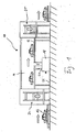
- FIG. 1 is a part of a paint shop for motor vehicle bodies in a not to scale and highly schematic longitudinal section shown.
- the part shown is a drying area 10 for drying previously coated motor vehicle bodies, to which two lifting stations, which are to be explained in greater detail, are located upstream or downstream.
- the drying area 10 includes an elongated housing 14, on the bottom of a 16 indicated conveyor for the motor vehicle bodies 12 is attached.
- This conveying device 16 may be, for example, a roller conveyor, a chain conveyor or a combination of both.
- the drying area 10 further includes a heating device 18, which is indicated only schematically, and which serves to blow hot air into distribution channels from below, which run along the longitudinal sides of the housing 14.
- the enriched with solvent vapors hot air can be supplied via an outlet 20 back to the heater 18, from which it is cleaned, heated and returned to the housing 14.
- the housing 14 is raised a few meters from a floor 22 of a surrounding building. In this way it is prevented that the heater 18 in the housing 14 introduced hot air in larger quantities at the entrance and at the exit of the housing 14 escapes from this.
- the increased arrangement of the housing 14 relative to the floor 22 makes it necessary to lift the motor vehicle bodies 12 before they can be conveyed through the drying area 10. Conversely, the motor vehicle bodies 12 must be lowered again at the exit of the drying area 10.
- lifting stations 24 and 25 For raising and lowering of the motor vehicle bodies 12 lifting stations 24 and 25 are provided, the details of which below with reference to the FIGS. 2 to 5 be explained in more detail.
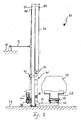
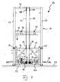
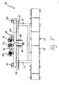
- FIGS. 2 to 5 show the lifting station 24 in side elevation in different stroke positions, a rear view and a top view.
- the lifting station 24 has two vertical guide posts 26, 28, which together with an upper cross-beam 30, a central cross-beam 32 and a lower cross-beam 33 form a support structure 34.
- the middle cross-beam 32 is connected via two fastening struts 36, 37 with a building intermediate ceiling 38 to derive on the guide posts 26, 28 acting tilting moments.
- the guide posts 26, 28 and the transverse members 30, 32, 33 are each made of steel tubes with a circular cross-section.
- the small area moment of inertia of Tubes allow a high rigidity of the support structure 34 with low material usage.
- a lifting slide 40 which can be moved in the vertical direction and is fixed relative to the supporting structure 34 in the horizontal, is supported on the guide posts 26, 28 in a manner which will be explained in more detail below.
- the lifting carriage 40 is composed of two vertical frame members 42, 44, two horizontal frame members 46, 48 and two stiffening struts 50, 52.
- the frame members 42, 44, 46, 48 and the stiffening struts 50, 52 are also made of round tubes and joined together by welding.
- load arms 54, 56 which are also made of round tubes.
- the load arms 54, 56 carry a generally designated 58 roller conveyor which includes a plurality of successively arranged axes.
- the axes are driven by an electric motor and carry at their ends rollers 60. Since such roller conveyors 58 are known in the art as such, the explanation of further details is omitted here.
- a vehicle body 12 is shown mounted on a support, also referred to as skid, indicated at 62 in the drawings.
- the Skid 62 can be moved by means of the driven rollers 60 in the longitudinal direction of the roller conveyor 58.
- the lifting carriage 40 is supported on the support structure 34 by a total of four guide rollers resting against the guide posts 26, 28 along a circular arc.
- Two guide rollers are mounted in the rear region of the vertical frame members 42, 44 at the same height and are located on the front of the guide post 26 and 28 at. They are therefore referred to below as the front guide rollers 64, 66.
- Two further, hereinafter referred to as the rear guide rollers 68, 70 rollers are mounted at angles 72 and 74 which go further up from the vertical frame members 42, 44 of the lifting carriage 40 and the guide posts 26, 28 so far embrace from the side, that the rear guide rollers 68, 70 abut against the rear sides of the guide posts 26, 28.
- the guide rollers 64, 66, 68, 70 are slidably mounted and thus low maintenance.
- the shape of the guide rollers is chosen so that the rolling surfaces along circular lines on the tubular guide posts 26, 28 abut. Since the guide rollers 64, 66, 68, 70 also partially surround the guide posts 26, 28 laterally, the lifting carriage 40 is secured not only against tilting about a horizontal tilting axis but also laterally, ie along the longitudinal direction of the transverse members 30, 32, 33 the support structure 34 fixed. Further details and variants to guide the guide rollers 64, 66, 68, 70 on the guide posts 26, 28 are discussed below with reference to the FIGS. 6a to 6e explained.
- a cable drive with two steel cables 76, 78 is provided.
- the two steel cables 76, 78 are attached to cable fittings 80 and 82 on the upper cross-beam 30.
- the free end of the steel cables 76, 78 is each guided in the manner of a simple pulley over a pulley 84 and 86, which are fixed to the upper horizontal frame member 46 of the lifting carriage 40.
- guide rollers 88, 90 the steel cables 76, 78 are guided back down, where they are rolled up on cable drums 92, 94.
- the cable drums 92, 94 are driven together by a drive shaft 96 which can be rotated by a drive motor 100 via a gear 98 in rotation.
- a cable actuator 102 is provided.
- the cable driver 102 includes a cable drum on which a thin measuring cable 104 is rolled up with low elongation.
- the cable drum can be arranged further away from the support structure 34 when providing additional deflection rollers.
- the free end of the measuring cable 104 is connected to the lifting carriage 40, here with its lower frame part 48. Ensuring spring loading of the drum ensures that the measuring part 104 is always tensioned.
- the drum, on which the measuring cable 104 is rolled, is connected to a rotary encoder which detects the angular position of the drum exactly. In this way, it is possible to precisely determine the vertical position of the lifting carriage 40 via the rotational position of the drum.
- an additional reference point generator (not shown) may be fastened to the support structure 34, which generates a signal when the lifting carriage 40 passes by.
- the position information determined by the cable sensor in this position can then be compared with the height at which the reference point sensor is located.
- the cable driver 102 is connected to a control of the lifting station 24.
- the controller has the task of driving the drive motor 100 such that the lifting carriage 40 moves to a desired height supplied to the control with a predetermined speed profile and the lifting 40 stops exactly at the desired height.
- the conveyor system 16 takes over the skid 62 with the vehicle body 12 and guides it through the housing 14 through which hot air flows.
- the motor vehicle body 12 is moved by means of the second lifting station 25 lowered and transferred to a subsequent conveyor line.
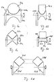
- FIGS. 6a to 6e show different variants for cross sections of the guide posts 26, 28 and corresponding shapes of the guide rollers 64, 66, 68, 70th
- the guide post 26a When in the FIG. 6a As shown, the guide post 26a also has a circular cross section.
- the guide roller 64a has a rolling surface 106a which can be described by rotating a parabola 108a about the rotation axis 110a of the guide roller 64a.
- the guide roller 64a thus abuts the guide post 26a at two points and is thus fixed relative to it both in the radial direction and in the axial direction.
- FIG. 6b shows a variant in which the guide roller 64b facing surface of the guide post 26b, parabolic curved. In this way, the guide roller 64b abuts along a line on the guide post 26b.
- the guide post 26c has an approximately square cross section, although one edge faces the guide roller 64c.
- FIG. 6d shown variant corresponds functionally largely to those in the FIG. 6c is shown.
- the guide roller 64c is made of figure 6c divided on the two lying in a height guide rollers 64d and 66d.
- the guide roller 64e has a cylindrical center section 107, at the end faces of which tapered flanges 109, 109 'follow.
- FIG. 7 shows a further variant in which the guide posts 26, 28 are not attached via fastening struts 36 to a building part. Instead, the guide post 26 passes over an elbow 112 in a foot 114, which is connected via bottom plates 116, 118 to the building floor 22.
- the foot 114 may be formed, for example, as a steel profile.
- FIG. 8 in a plan view variant differs from that in the FIGS. 2 to 4 shown lifting station 24 characterized in that in addition to the drive motor 100, a redundant drive motor 100 'is provided which can be coupled to the drive shaft 96 in case of failure of the drive motor 100.
- the drive unit for the lifting carriage 40 with the cable drums 92, 94, the drive shaft 96, the gear 98 and the drive motor 100 is not arranged directly below the lifting carriage 40, but horizontally offset to the rear. This allows the drive unit from the remaining parts of the lifting station 24 by a partition 120 divide.
- the in the FIG. 9 shown variant only requires that additional pulleys 122, 124 are provided for the steel cables 76 and 78, respectively. These deflection rollers 122, 124 may be arranged, for example, directly above the building floor 22, but also higher, approximately at the level of the lower crosspiece 33.
- the intermediate wall 120 is provided with openings 126, 128, through which the steel cables 76, 78 can be guided to the cable drums 92, 94.
Landscapes
- Life Sciences & Earth Sciences (AREA)
- Engineering & Computer Science (AREA)
- Geology (AREA)
- Mechanical Engineering (AREA)
- Structural Engineering (AREA)
- Grinding Of Cylindrical And Plane Surfaces (AREA)
- Load-Engaging Elements For Cranes (AREA)
- Treatment Of Fiber Materials (AREA)
- Spray Control Apparatus (AREA)
- Vehicle Cleaning, Maintenance, Repair, Refitting, And Outriggers (AREA)
- Automobile Manufacture Line, Endless Track Vehicle, Trailer (AREA)
- Intermediate Stations On Conveyors (AREA)
Claims (14)
- Installation de traitement de surfaces, notamment dévolue au traitement de carrosseries de véhicules et munie d'un poste de levage (24, 25) affecté à la transposition verticale d'un objet (12), ledit poste de levage comprenant :a) une structure fixe de support (34), présentant deux montants verticaux de guidage (26, 28),b) un chariot de levage (40) prenant appui, sur ladite structure de support (34), par l'intermédiaire de rouleaux de guidage (64, 66, 68, 70) en applique contre lesdits montants de guidage (26, 28) en au moins deux points, etc) un bras de charge (54), fixé audit chariot de levage (40) et conçu pour recevoir ledit objet (12),caractérisée par le fait
qu'au moins un rouleau de guidage (64, 66, 68, 70 ; 64a ; 64b ; 64c ; 64d, 66d) présente une forme non cylindrique, de manière à obtenir une direction de guidage s'écartant d'une direction radiale,
que deux rouleaux de guidage (64, 66) sont en applique contre le côté des montants de guidage (26, 28) qui pointe vers le chariot de levage (40), et deux rouleaux de guidage (68, 70) sont en applique contre le côté desdits montants de guidage (26, 28) qui est tourné à l'opposé dudit chariot de levage (40), sachant que lesdits rouleaux de guidage (64, 66), appliqués contre le côté des montants de guidage (26, 28) qui pointe vers le chariot de levage (40), sont disposés au-dessous desdits rouleaux de guidage (68, 70) appliqués contre le côté desdits montants de guidage (26, 28) qui est tourné à l'opposé dudit chariot de levage (40),
qu'un moyen de traction (76, 78), prévu pour la montée et la descente du chariot de levage (40), relie ledit chariot de levage à un moteur d'entraînement (100),
que ledit moteur d'entraînement (100) est séparé desdits montants de guidage (26, 28) par une cloison protectrice (120),
que la cloison protectrice (120) comporte des orifices (126, 128), à travers lesquels ledit moyen de traction (76, 78) est guidé avec franchissement de ladite cloison protectrice, et qu'un rouleau de renvoi (122, 124), renvoyant ledit moyen de traction (76, 78), est interposé entre lesdits montants de guidage (26, 28) et lesdits orifices (126, 128). - Installation de traitement de surfaces, selon la revendication 1, caractérisée par le fait que la forme du rouleau de guidage (64, 66, 68, 70 ; 64a ; 64b), à présence minimale, est déterminée par rotation d'un profil radial courbe autour d'un axe de rotation (110a ; 110b) dudit rouleau de guidage à présence minimale.
- Installation de traitement de surfaces, selon la revendication 2, caractérisée par le fait que le profil radial (108a) présente une courbure en arc de cercle.
- Installation de traitement de surfaces, selon l'une des revendications précédentes, caractérisée par le fait que le montant de guidage (26, 28 ; 26a), contre lequel le rouleau de guidage (64, 66, 68, 70 ; 64a) à présence minimale est en applique, offre une section transversale configurée en arc de cercle, au moins en direction dudit rouleau de guidage à présence minimale.
- Installation de traitement de surfaces, selon la revendication 1, caractérisée par le fait que le rouleau de guidage (64c ; 64d, 66d), à présence minimale, est muni d'au moins une région conique.
- Installation de traitement de surfaces, selon l'une des revendications précédentes, caractérisée par le fait que le rouleau de guidage (64, 66, 68, 70), à présence minimale, est monté de manière glissante.
- Installation de traitement de surfaces, selon l'une des revendications précédentes, caractérisée par le fait que le rouleau de guidage (64, 66, 68, 70), à présence minimale, est doté d'une surface de roulement en applique contre le montant de guidage et fabriquée en une matière plastique.
- Installation de traitement de surfaces, selon l'une des revendications précédentes, caractérisée par le fait que le moyen de traction (76, 78) est guidé par l'intermédiaire d'un rouleau de renvoi (84, 86) placé à l'extrémité supérieure du poste de levage (24, 25).
- Installation de traitement de surfaces, selon l'une des revendications précédentes, caractérisée par le fait que le moyen de traction est un câble (76, 78) ou un ruban.
- Installation de traitement de surfaces, selon la revendication 9, caractérisée par un palan (76, 78, 80, 82, 84, 86, 88, 90) diminuant la force requise pour provoquer la montée du chariot de levage (40).
- Installation de traitement de surfaces, selon l'une des revendications précédentes, caractérisée par un capteur (102) de traction de câbles, affecté à la mesure de la hauteur du chariot de levage (40) par rapport à un point de référence.
- Installation de traitement de surfaces, selon la revendication 11, caractérisée par un interrupteur fixe à points d'indexage, qui coopère avec le capteur (102) de traction de câbles et permet une harmonisation des informations de hauteur, fournies par ledit capteur (102) de traction de câbles, avec la hauteur de référence à laquelle ledit interrupteur à points d'indexage est situé.
- Installation de traitement de surfaces, selon l'une des revendications précédentes, caractérisée par le fait que la structure de support (34) est reliée à un ensemble stationnaire d'appui, à proximité de l'extrémité supérieure du poste de levage (24, 25).
- Installation de traitement de surfaces, selon l'une des revendications 1 à 12, caractérisée par le fait que les montants de guidage (26') sont reliés à une semelle horizontale (114) pouvant être fixée au sol (22) d'un bâtiment, et s'étendant dans la direction du bras de charge (54).
Priority Applications (4)
| Application Number | Priority Date | Filing Date | Title |
|---|---|---|---|
| AT05015921T ATE540893T1 (de) | 2005-07-22 | 2005-07-22 | Oberflächenbehandlungsanlage mit einer hubstation,und hubstation mit nichtzylindrischen führungsrollen |
| EP05015921A EP1746065B1 (fr) | 2005-07-22 | 2005-07-22 | Installation de traitement de surface avec dispositif de levage, et dispositif de levage avec galets de guidage non-cylindriques |
| ES05015921T ES2380888T3 (es) | 2005-07-22 | 2005-07-22 | Instalación de tratamiento de superficies con una estación de elevación, y estación de elevación con rodillos de guiado no cilíndricos |
| PL05015921T PL1746065T3 (pl) | 2005-07-22 | 2005-07-22 | Instalacja do obróbki powierzchni ze stanowiskiem podnośnym oraz stanowisko podnośne z nie cylindrycznymi rolkami prowadzącymi |
Applications Claiming Priority (1)
| Application Number | Priority Date | Filing Date | Title |
|---|---|---|---|
| EP05015921A EP1746065B1 (fr) | 2005-07-22 | 2005-07-22 | Installation de traitement de surface avec dispositif de levage, et dispositif de levage avec galets de guidage non-cylindriques |
Publications (2)
| Publication Number | Publication Date |
|---|---|
| EP1746065A1 EP1746065A1 (fr) | 2007-01-24 |
| EP1746065B1 true EP1746065B1 (fr) | 2012-01-11 |
Family
ID=35453316
Family Applications (1)
| Application Number | Title | Priority Date | Filing Date |
|---|---|---|---|
| EP05015921A Expired - Lifetime EP1746065B1 (fr) | 2005-07-22 | 2005-07-22 | Installation de traitement de surface avec dispositif de levage, et dispositif de levage avec galets de guidage non-cylindriques |
Country Status (4)
| Country | Link |
|---|---|
| EP (1) | EP1746065B1 (fr) |
| AT (1) | ATE540893T1 (fr) |
| ES (1) | ES2380888T3 (fr) |
| PL (1) | PL1746065T3 (fr) |
Families Citing this family (1)
| Publication number | Priority date | Publication date | Assignee | Title |
|---|---|---|---|---|
| JP6561697B2 (ja) * | 2015-09-01 | 2019-08-21 | 株式会社ダイフク | 昇降設備及び搬送システム |
Citations (1)
| Publication number | Priority date | Publication date | Assignee | Title |
|---|---|---|---|---|
| US2857985A (en) * | 1955-08-18 | 1958-10-28 | Simmons Ind Inc | Automobile lifting apparatus |
Family Cites Families (5)
| Publication number | Priority date | Publication date | Assignee | Title |
|---|---|---|---|---|
| GB1538355A (en) * | 1976-07-09 | 1979-01-17 | Towmotor Corp | Lift truck mast assembly |
| JPH1135162A (ja) | 1997-07-15 | 1999-02-09 | Miura Tekkosho:Kk | 用紙高積み機 |
| US6571970B1 (en) | 2000-10-16 | 2003-06-03 | Rapistan Systems Advertising Corp. | Monorail telescopic carrier |
| DE10238493A1 (de) * | 2002-08-22 | 2004-03-04 | Dürr Automotion Gmbh | Fördervorrichtung und Verfahren zum Fördern eines Werkstücks |
| DE10318085A1 (de) | 2003-04-17 | 2004-11-18 | Bürener Maschinenfabrik GmbH | Säulenheber |
-
2005
- 2005-07-22 ES ES05015921T patent/ES2380888T3/es not_active Expired - Lifetime
- 2005-07-22 AT AT05015921T patent/ATE540893T1/de active
- 2005-07-22 EP EP05015921A patent/EP1746065B1/fr not_active Expired - Lifetime
- 2005-07-22 PL PL05015921T patent/PL1746065T3/pl unknown
Patent Citations (1)
| Publication number | Priority date | Publication date | Assignee | Title |
|---|---|---|---|---|
| US2857985A (en) * | 1955-08-18 | 1958-10-28 | Simmons Ind Inc | Automobile lifting apparatus |
Also Published As
| Publication number | Publication date |
|---|---|
| EP1746065A1 (fr) | 2007-01-24 |
| ES2380888T3 (es) | 2012-05-21 |
| ATE540893T1 (de) | 2012-01-15 |
| PL1746065T3 (pl) | 2012-06-29 |
Similar Documents
| Publication | Publication Date | Title |
|---|---|---|
| EP1181467B2 (fr) | Table elevatrice a compas | |
| DE10063448C5 (de) | Anlage zur Behandlung, insbesondere zum Lackieren, von Gegenständen, insbesondere von Fahrzeugkarosserien | |
| EP2578520B1 (fr) | Dispositif d'acheminement | |
| DE3738973C1 (de) | Vorrichtung zum Auswechseln elastischer Superkalander-Walzen | |
| EP0069239B1 (fr) | Dispositif d'entraînement pour le déplacement de demi-produits oblongs | |
| EP2703329B1 (fr) | Ascenseur | |
| EP0155375B1 (fr) | Manipulateur d'examen des cuves sous pression comportant une ouverture dans la partie supérieure | |
| EP1485312B1 (fr) | Dispositif de traitement, notamment de peinture par immersion cataphoretique de carrosseries automobiles | |
| EP0232529B1 (fr) | Unité de positionnement pour tête de préhension d'un palettiseur ou dispositif de positionnement similaire | |
| EP1784288B1 (fr) | Dispositif pour recouvrir, en particulier pour peindre des articles, en particulier des carrosseries de vehicules | |
| EP1746065B1 (fr) | Installation de traitement de surface avec dispositif de levage, et dispositif de levage avec galets de guidage non-cylindriques | |
| DE10211214C1 (de) | Anlage zum Behandeln, insbesondere zum kataphoretischen Tauchlackieren, von Gegenständen, insbesondere von Fahrzeugkarosserien | |
| EP3788190B1 (fr) | Ouvreuse de balles pour l'ouvraison de balles de fibres comprimées | |
| DE102004032954B4 (de) | Oberflächenbehandlungsanlage mit einer Hubstation | |
| DE202004021036U1 (de) | Oberflächenbehandlungsanlage mit einer Hubstation | |
| EP1277521A2 (fr) | Installation de revêtement comprenant une bande de couverture pour une ouverture d'un carter | |
| EP4304960A1 (fr) | Installation de traitement et procédé de traitement de pièces | |
| EP2588376A2 (fr) | Dispositif d'emballage et son procédé de fonctionnement | |
| EP4344430B1 (fr) | Système d'ascenseur sans salle des machines | |
| DE2314077C3 (de) | Vorrichtung zum Transportieren von Rohren durch eine Wärmebehandlungseinrichtung | |
| AT519207A1 (de) | Fördereinrichtung zum Fördern von Produkten | |
| WO2025252881A1 (fr) | Dispositif de levage et de transport, en particulier pour déplacer une charge lourde, et système de levage à câbles toronnés | |
| EP3201108A1 (fr) | Système de transport de pieces | |
| DE20221036U1 (de) | Vorrichtung zum Umsetzen von Transportpaletten, insbesondere Skids | |
| DE2706108C2 (de) | Verfahren und Einrichtung zur Lageänderung beweglicher Abschnitte in Bühnenböden |
Legal Events
| Date | Code | Title | Description |
|---|---|---|---|
| PUAI | Public reference made under article 153(3) epc to a published international application that has entered the european phase |
Free format text: ORIGINAL CODE: 0009012 |
|
| AK | Designated contracting states |
Kind code of ref document: A1 Designated state(s): AT BE BG CH CY CZ DE DK EE ES FI FR GB GR HU IE IS IT LI LT LU LV MC NL PL PT RO SE SI SK TR |
|
| AX | Request for extension of the european patent |
Extension state: AL BA HR MK YU |
|
| 17P | Request for examination filed |
Effective date: 20070716 |
|
| AKX | Designation fees paid |
Designated state(s): AT BE BG CH CY CZ DE DK EE ES FI FR GB GR HU IE IS IT LI LT LU LV MC NL PL PT RO SE SI SK TR |
|
| 17Q | First examination report despatched |
Effective date: 20071011 |
|
| R17C | First examination report despatched (corrected) |
Effective date: 20100202 |
|
| RAP1 | Party data changed (applicant data changed or rights of an application transferred) |
Owner name: EISENMANN AG |
|
| GRAP | Despatch of communication of intention to grant a patent |
Free format text: ORIGINAL CODE: EPIDOSNIGR1 |
|
| GRAS | Grant fee paid |
Free format text: ORIGINAL CODE: EPIDOSNIGR3 |
|
| GRAA | (expected) grant |
Free format text: ORIGINAL CODE: 0009210 |
|
| AK | Designated contracting states |
Kind code of ref document: B1 Designated state(s): AT BE BG CH CY CZ DE DK EE ES FI FR GB GR HU IE IS IT LI LT LU LV MC NL PL PT RO SE SI SK TR |
|
| REG | Reference to a national code |
Ref country code: GB Ref legal event code: FG4D Free format text: NOT ENGLISH |
|
| REG | Reference to a national code |
Ref country code: CH Ref legal event code: EP |
|
| REG | Reference to a national code |
Ref country code: AT Ref legal event code: REF Ref document number: 540893 Country of ref document: AT Kind code of ref document: T Effective date: 20120115 |
|
| REG | Reference to a national code |
Ref country code: DE Ref legal event code: R081 Ref document number: 502005012313 Country of ref document: DE Owner name: EISENMANN SE, DE Free format text: FORMER OWNER: EISENMANN ANLAGENBAU GMBH & CO. KG, 71032 BOEBLINGEN, DE |
|
| REG | Reference to a national code |
Ref country code: IE Ref legal event code: FG4D |
|
| REG | Reference to a national code |
Ref country code: DE Ref legal event code: R096 Ref document number: 502005012313 Country of ref document: DE Effective date: 20120308 |
|
| REG | Reference to a national code |
Ref country code: NL Ref legal event code: VDEP Effective date: 20120111 |
|
| REG | Reference to a national code |
Ref country code: ES Ref legal event code: FG2A Ref document number: 2380888 Country of ref document: ES Kind code of ref document: T3 Effective date: 20120521 |
|
| PG25 | Lapsed in a contracting state [announced via postgrant information from national office to epo] |
Ref country code: SI Free format text: LAPSE BECAUSE OF FAILURE TO SUBMIT A TRANSLATION OF THE DESCRIPTION OR TO PAY THE FEE WITHIN THE PRESCRIBED TIME-LIMIT Effective date: 20120111 |
|
| LTIE | Lt: invalidation of european patent or patent extension |
Effective date: 20120111 |
|
| REG | Reference to a national code |
Ref country code: PL Ref legal event code: T3 |
|
| PG25 | Lapsed in a contracting state [announced via postgrant information from national office to epo] |
Ref country code: BG Free format text: LAPSE BECAUSE OF FAILURE TO SUBMIT A TRANSLATION OF THE DESCRIPTION OR TO PAY THE FEE WITHIN THE PRESCRIBED TIME-LIMIT Effective date: 20120411 Ref country code: LT Free format text: LAPSE BECAUSE OF FAILURE TO SUBMIT A TRANSLATION OF THE DESCRIPTION OR TO PAY THE FEE WITHIN THE PRESCRIBED TIME-LIMIT Effective date: 20120111 Ref country code: NL Free format text: LAPSE BECAUSE OF FAILURE TO SUBMIT A TRANSLATION OF THE DESCRIPTION OR TO PAY THE FEE WITHIN THE PRESCRIBED TIME-LIMIT Effective date: 20120111 Ref country code: IS Free format text: LAPSE BECAUSE OF FAILURE TO SUBMIT A TRANSLATION OF THE DESCRIPTION OR TO PAY THE FEE WITHIN THE PRESCRIBED TIME-LIMIT Effective date: 20120511 |
|
| REG | Reference to a national code |
Ref country code: IE Ref legal event code: FD4D |
|
| PG25 | Lapsed in a contracting state [announced via postgrant information from national office to epo] |
Ref country code: PT Free format text: LAPSE BECAUSE OF FAILURE TO SUBMIT A TRANSLATION OF THE DESCRIPTION OR TO PAY THE FEE WITHIN THE PRESCRIBED TIME-LIMIT Effective date: 20120511 Ref country code: FI Free format text: LAPSE BECAUSE OF FAILURE TO SUBMIT A TRANSLATION OF THE DESCRIPTION OR TO PAY THE FEE WITHIN THE PRESCRIBED TIME-LIMIT Effective date: 20120111 Ref country code: GR Free format text: LAPSE BECAUSE OF FAILURE TO SUBMIT A TRANSLATION OF THE DESCRIPTION OR TO PAY THE FEE WITHIN THE PRESCRIBED TIME-LIMIT Effective date: 20120412 Ref country code: LV Free format text: LAPSE BECAUSE OF FAILURE TO SUBMIT A TRANSLATION OF THE DESCRIPTION OR TO PAY THE FEE WITHIN THE PRESCRIBED TIME-LIMIT Effective date: 20120111 |
|
| PG25 | Lapsed in a contracting state [announced via postgrant information from national office to epo] |
Ref country code: CY Free format text: LAPSE BECAUSE OF FAILURE TO SUBMIT A TRANSLATION OF THE DESCRIPTION OR TO PAY THE FEE WITHIN THE PRESCRIBED TIME-LIMIT Effective date: 20120111 |
|
| PG25 | Lapsed in a contracting state [announced via postgrant information from national office to epo] |
Ref country code: SE Free format text: LAPSE BECAUSE OF FAILURE TO SUBMIT A TRANSLATION OF THE DESCRIPTION OR TO PAY THE FEE WITHIN THE PRESCRIBED TIME-LIMIT Effective date: 20120111 Ref country code: RO Free format text: LAPSE BECAUSE OF FAILURE TO SUBMIT A TRANSLATION OF THE DESCRIPTION OR TO PAY THE FEE WITHIN THE PRESCRIBED TIME-LIMIT Effective date: 20120111 Ref country code: DK Free format text: LAPSE BECAUSE OF FAILURE TO SUBMIT A TRANSLATION OF THE DESCRIPTION OR TO PAY THE FEE WITHIN THE PRESCRIBED TIME-LIMIT Effective date: 20120111 Ref country code: EE Free format text: LAPSE BECAUSE OF FAILURE TO SUBMIT A TRANSLATION OF THE DESCRIPTION OR TO PAY THE FEE WITHIN THE PRESCRIBED TIME-LIMIT Effective date: 20120111 Ref country code: CZ Free format text: LAPSE BECAUSE OF FAILURE TO SUBMIT A TRANSLATION OF THE DESCRIPTION OR TO PAY THE FEE WITHIN THE PRESCRIBED TIME-LIMIT Effective date: 20120111 Ref country code: IE Free format text: LAPSE BECAUSE OF FAILURE TO SUBMIT A TRANSLATION OF THE DESCRIPTION OR TO PAY THE FEE WITHIN THE PRESCRIBED TIME-LIMIT Effective date: 20120111 |
|
| PLBE | No opposition filed within time limit |
Free format text: ORIGINAL CODE: 0009261 |
|
| STAA | Information on the status of an ep patent application or granted ep patent |
Free format text: STATUS: NO OPPOSITION FILED WITHIN TIME LIMIT |
|
| PG25 | Lapsed in a contracting state [announced via postgrant information from national office to epo] |
Ref country code: SK Free format text: LAPSE BECAUSE OF FAILURE TO SUBMIT A TRANSLATION OF THE DESCRIPTION OR TO PAY THE FEE WITHIN THE PRESCRIBED TIME-LIMIT Effective date: 20120111 |
|
| 26N | No opposition filed |
Effective date: 20121012 |
|
| BERE | Be: lapsed |
Owner name: EISENMANN A.G. Effective date: 20120731 |
|
| REG | Reference to a national code |
Ref country code: DE Ref legal event code: R097 Ref document number: 502005012313 Country of ref document: DE Effective date: 20121012 |
|
| PG25 | Lapsed in a contracting state [announced via postgrant information from national office to epo] |
Ref country code: MC Free format text: LAPSE BECAUSE OF NON-PAYMENT OF DUE FEES Effective date: 20120731 |
|
| REG | Reference to a national code |
Ref country code: CH Ref legal event code: PL |
|
| PG25 | Lapsed in a contracting state [announced via postgrant information from national office to epo] |
Ref country code: CH Free format text: LAPSE BECAUSE OF NON-PAYMENT OF DUE FEES Effective date: 20120731 Ref country code: LI Free format text: LAPSE BECAUSE OF NON-PAYMENT OF DUE FEES Effective date: 20120731 |
|
| PG25 | Lapsed in a contracting state [announced via postgrant information from national office to epo] |
Ref country code: BE Free format text: LAPSE BECAUSE OF NON-PAYMENT OF DUE FEES Effective date: 20120731 |
|
| PG25 | Lapsed in a contracting state [announced via postgrant information from national office to epo] |
Ref country code: TR Free format text: LAPSE BECAUSE OF FAILURE TO SUBMIT A TRANSLATION OF THE DESCRIPTION OR TO PAY THE FEE WITHIN THE PRESCRIBED TIME-LIMIT Effective date: 20120111 |
|
| PG25 | Lapsed in a contracting state [announced via postgrant information from national office to epo] |
Ref country code: LU Free format text: LAPSE BECAUSE OF NON-PAYMENT OF DUE FEES Effective date: 20120722 |
|
| PG25 | Lapsed in a contracting state [announced via postgrant information from national office to epo] |
Ref country code: HU Free format text: LAPSE BECAUSE OF FAILURE TO SUBMIT A TRANSLATION OF THE DESCRIPTION OR TO PAY THE FEE WITHIN THE PRESCRIBED TIME-LIMIT Effective date: 20050722 |
|
| PGFP | Annual fee paid to national office [announced via postgrant information from national office to epo] |
Ref country code: FR Payment date: 20140722 Year of fee payment: 10 |
|
| REG | Reference to a national code |
Ref country code: DE Ref legal event code: R082 Ref document number: 502005012313 Country of ref document: DE Representative=s name: OSTERTAG & PARTNER, PATENTANWAELTE MBB, DE Ref country code: DE Ref legal event code: R081 Ref document number: 502005012313 Country of ref document: DE Owner name: EISENMANN SE, DE Free format text: FORMER OWNER: EISENMANN AG, 71032 BOEBLINGEN, DE |
|
| REG | Reference to a national code |
Ref country code: FR Ref legal event code: ST Effective date: 20160513 |
|
| REG | Reference to a national code |
Ref country code: FR Ref legal event code: RN Effective date: 20160726 |
|
| PG25 | Lapsed in a contracting state [announced via postgrant information from national office to epo] |
Ref country code: FR Free format text: LAPSE BECAUSE OF NON-PAYMENT OF DUE FEES Effective date: 20150731 |
|
| PGFP | Annual fee paid to national office [announced via postgrant information from national office to epo] |
Ref country code: DE Payment date: 20160722 Year of fee payment: 12 Ref country code: GB Payment date: 20160721 Year of fee payment: 12 Ref country code: IT Payment date: 20160725 Year of fee payment: 12 |
|
| REG | Reference to a national code |
Ref country code: FR Ref legal event code: D5 Effective date: 20161013 |
|
| PGFP | Annual fee paid to national office [announced via postgrant information from national office to epo] |
Ref country code: PL Payment date: 20160713 Year of fee payment: 12 Ref country code: AT Payment date: 20160721 Year of fee payment: 12 |
|
| PGFP | Annual fee paid to national office [announced via postgrant information from national office to epo] |
Ref country code: ES Payment date: 20160715 Year of fee payment: 12 |
|
| REG | Reference to a national code |
Ref country code: DE Ref legal event code: R119 Ref document number: 502005012313 Country of ref document: DE |
|
| REG | Reference to a national code |
Ref country code: AT Ref legal event code: MM01 Ref document number: 540893 Country of ref document: AT Kind code of ref document: T Effective date: 20170722 |
|
| GBPC | Gb: european patent ceased through non-payment of renewal fee |
Effective date: 20170722 |
|
| PG25 | Lapsed in a contracting state [announced via postgrant information from national office to epo] |
Ref country code: DE Free format text: LAPSE BECAUSE OF NON-PAYMENT OF DUE FEES Effective date: 20180201 Ref country code: GB Free format text: LAPSE BECAUSE OF NON-PAYMENT OF DUE FEES Effective date: 20170722 |
|
| PG25 | Lapsed in a contracting state [announced via postgrant information from national office to epo] |
Ref country code: AT Free format text: LAPSE BECAUSE OF NON-PAYMENT OF DUE FEES Effective date: 20170722 |
|
| PG25 | Lapsed in a contracting state [announced via postgrant information from national office to epo] |
Ref country code: IT Free format text: LAPSE BECAUSE OF NON-PAYMENT OF DUE FEES Effective date: 20170722 |
|
| REG | Reference to a national code |
Ref country code: ES Ref legal event code: FD2A Effective date: 20181030 |
|
| PG25 | Lapsed in a contracting state [announced via postgrant information from national office to epo] |
Ref country code: PL Free format text: LAPSE BECAUSE OF NON-PAYMENT OF DUE FEES Effective date: 20170722 |
|
| PG25 | Lapsed in a contracting state [announced via postgrant information from national office to epo] |
Ref country code: ES Free format text: LAPSE BECAUSE OF NON-PAYMENT OF DUE FEES Effective date: 20170723 |