EP1746266A2 - Doppel Anker zür Übertragung der Bewegung auf die Lüfter für Kühlung der Brennkraftmaschine eines Kraftfahrzeuges - Google Patents
Doppel Anker zür Übertragung der Bewegung auf die Lüfter für Kühlung der Brennkraftmaschine eines Kraftfahrzeuges Download PDFInfo
- Publication number
- EP1746266A2 EP1746266A2 EP06076393A EP06076393A EP1746266A2 EP 1746266 A2 EP1746266 A2 EP 1746266A2 EP 06076393 A EP06076393 A EP 06076393A EP 06076393 A EP06076393 A EP 06076393A EP 1746266 A2 EP1746266 A2 EP 1746266A2
- Authority
- EP
- European Patent Office
- Prior art keywords
- armature
- fan
- bell member
- clutch
- magnet
- Prior art date
- Legal status (The legal status is an assumption and is not a legal conclusion. Google has not performed a legal analysis and makes no representation as to the accuracy of the status listed.)
- Granted
Links
Images

Classifications
-
- F—MECHANICAL ENGINEERING; LIGHTING; HEATING; WEAPONS; BLASTING
- F01—MACHINES OR ENGINES IN GENERAL; ENGINE PLANTS IN GENERAL; STEAM ENGINES
- F01P—COOLING OF MACHINES OR ENGINES IN GENERAL; COOLING OF INTERNAL-COMBUSTION ENGINES
- F01P7/00—Controlling of coolant flow
- F01P7/02—Controlling of coolant flow the coolant being cooling-air
- F01P7/04—Controlling of coolant flow the coolant being cooling-air by varying pump speed, e.g. by changing pump-drive gear ratio
-
- F—MECHANICAL ENGINEERING; LIGHTING; HEATING; WEAPONS; BLASTING
- F01—MACHINES OR ENGINES IN GENERAL; ENGINE PLANTS IN GENERAL; STEAM ENGINES
- F01P—COOLING OF MACHINES OR ENGINES IN GENERAL; COOLING OF INTERNAL-COMBUSTION ENGINES
- F01P7/00—Controlling of coolant flow
- F01P7/02—Controlling of coolant flow the coolant being cooling-air
- F01P7/08—Controlling of coolant flow the coolant being cooling-air by cutting in or out of pumps
- F01P7/081—Controlling of coolant flow the coolant being cooling-air by cutting in or out of pumps using clutches, e.g. electro-magnetic or induction clutches
- F01P7/082—Controlling of coolant flow the coolant being cooling-air by cutting in or out of pumps using clutches, e.g. electro-magnetic or induction clutches using friction clutches
- F01P7/084—Controlling of coolant flow the coolant being cooling-air by cutting in or out of pumps using clutches, e.g. electro-magnetic or induction clutches using friction clutches actuated electromagnetically
-
- F—MECHANICAL ENGINEERING; LIGHTING; HEATING; WEAPONS; BLASTING
- F04—POSITIVE - DISPLACEMENT MACHINES FOR LIQUIDS; PUMPS FOR LIQUIDS OR ELASTIC FLUIDS
- F04D—NON-POSITIVE-DISPLACEMENT PUMPS
- F04D25/00—Pumping installations or systems
- F04D25/02—Units comprising pumps and their driving means
-
- F—MECHANICAL ENGINEERING; LIGHTING; HEATING; WEAPONS; BLASTING
- F04—POSITIVE - DISPLACEMENT MACHINES FOR LIQUIDS; PUMPS FOR LIQUIDS OR ELASTIC FLUIDS
- F04D—NON-POSITIVE-DISPLACEMENT PUMPS
- F04D25/00—Pumping installations or systems
- F04D25/02—Units comprising pumps and their driving means
- F04D25/022—Units comprising pumps and their driving means comprising a yielding coupling, e.g. hydraulic
-
- F—MECHANICAL ENGINEERING; LIGHTING; HEATING; WEAPONS; BLASTING
- F04—POSITIVE - DISPLACEMENT MACHINES FOR LIQUIDS; PUMPS FOR LIQUIDS OR ELASTIC FLUIDS
- F04D—NON-POSITIVE-DISPLACEMENT PUMPS
- F04D25/00—Pumping installations or systems
- F04D25/02—Units comprising pumps and their driving means
- F04D25/026—Units comprising pumps and their driving means with a magnetic coupling
Definitions
- the present invention relates to a dual armature device for transmitting the movement to fans for cooling the coolant in motor vehicles.
- DE-32 03 143 describes, for example, an arrangement in which the driving shaft is connected to the rotor of an electromagnetic clutch, which is engaged by an armature connected to the fan for direct driving, whereas low speed conditions make use of the engagement between a conducting disk, rotating with the transmission shaft, and the permanent magnets integral with the fan, said engagement causing transmission of movement at a low speed as a result of relative slipping between the two parts.
- the known devices do not envisage the possibility of maintaining an albeit slow rotation of the fan (fail safe mode) in the event of breakage and/or complete interruption of the power supply to the coils of the clutches as occurs for example in the case of total electrical failure.
- the technical problem which is posed, therefore, is that of providing a device for transmitting the rotational movement to a fan for cooling the coolant of motor vehicles, which allows the fan to rotate at a number of revolutions which is different from that of the driving shaft and can be determined depending on the actual cooling requirement of the engine, which device has compact dimensions and does not have large and costly projecting rotational masses and is formed by a limited number of costly parts.
- the device should be able to keep the fan stationary in an idle position and also ensure reliable rotation of the fan also in the event of malfunction of the associated power supply and control devices.
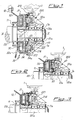
- the cooling fan 1 is fastened to a supporting bell member 1a arranged on a bearing 1b mounted on an extension 20a of the driving shaft 20 of the vehicle, so as to be coaxial with the axis of rotation thereof.
- longitudinal direction X-X will be understood as meaning that direction coinciding with/parallel to the longitudinal axis of the driving shaft.
- the same extension 20a of the shaft 20 also has mounted thereon, locked rotationally therewith, a rotor 31 which forms the rotating element of a first clutch 30 comprising an annular electromagnet 32 concentric with the rotor 31 and mounted on the outer race of a bearing 11 arranged between the rotating shaft and a fixed support flange 12 joined to the base 10 of the engine; the electromagnet 32 is electrically connected by means of wires 32a to a thermostat (not shown) for example for the temperature of the cooling fluid.
- a first armature 33 is arranged on the opposite side to the electromagnet 32 with respect to the rotor 31 and is connected to an annular flange 40 joined to the outer race 21a of a bearing 21 in turn keyed onto the shaft 20.
- connection between armature 33 and flange 40 is effected with the arrangement, in between, of a resilient member 33a able to allow axial movements of the armature 33, but prevent relative rotation of the armature and flange 40.
- Said flange 40 also supports the first part 210 of a second clutch 200, the other part 220 of which is integral with the bell member 1a of the fan 1.
- said first part 210 of the clutch comprises a retaining ring 213 which is made of non-magnetic material and which carries permanent magnets 214.
- the second clutch part 220 is formed by a ring 221 which is made of conductive material and integral with the bell member 1a which is made of non-magnetic material such as, for example, die-cast aluminium.
- the first part 210 of the second clutch forms the rotor part for generating the movement of the said clutch 200 which, by means of the flange 40 and the permanent magnets 214, causes the generation of Foucault currents resulting in induction linkage with the driven disk 211 which is rotationally driven, causing rotation of the bell member 1a and therefore the fan 1.
- a second armature 34 is arranged concentrically with the first armature 33, being arranged radially further outwards with respect to the first armature and being connected to the bell member 1a by means of a resilient membrane 34a connected to the bell member 1a with the arrangement, in between, of a resilient member 34a able to allow axial movements of the armature 34, but prevent relative rotation of the armature and bell member.
- the membrane 34a of the second armature 34 has a resistance in the axial direction greater than that of the membrane 33a of the first armature, therefore requiring a greater recall force in order to allow displacement of the armature towards the rotor.
- the second armature 34 also has radial dimensions much greater than those of the first armature 33.
- Fig. 4 shows a first example of a variation of embodiment of the device according to the invention in which the entire assembly is mounted on a fixed shaft 420a and the rotor 431 is mounted on the fixed shaft with a bearing 435 arranged in between; the rotor has an annular extension in the form of a pulley 431a able to engage with a corresponding drive belt 431b by means of which it actuates the said rotor 431.
- Fig. 5 shows a further embodiment of the device in which it is envisaged that the rotor 531 is connected to an extension 520a of the driving shaft and the second armature 34 is joined to the support 1a of the fan via a resilient bearing 534 able to absorb the torsional vibrations during engagement.
- Fig. 6 shows a further variation of embodiment, similar to that of Fig. 5, which envisages the presence of a second electromagnet 632, the current of which is in turn controlled, for actuation of the first armature 33.
- FIG. 6 also shows the presence of a permanent magnet 600 arranged between the second electromagnet 634 and the first armature 33; in a preferred embodiment, said magnet 600 is joined to a part 601 made of magnetizable material situated axially opposite the said armature 33.
- the magnet is magnetized in frontal segments alternating in the radial direction with N-S polarity, optionally also with several poles and with the presence of an iron part 602 arranged on the opposite side to that of the armature 33, having the function of a flow concentrator.
- the device also implements the so-called "fail-safe" condition since under normal operating conditions the power supplied to the second electromagnet 632 produces neutralization of the magnetic field recalling the armature 33, while in event of a total power failure, the magnet 600 is nevertheless able to recall the first armature 33 and ensure slow rotation of the fan 1 which ensures albeit minimum cooling of the engine coolant.
Landscapes
- Engineering & Computer Science (AREA)
- Mechanical Engineering (AREA)
- General Engineering & Computer Science (AREA)
- Chemical & Material Sciences (AREA)
- Combustion & Propulsion (AREA)
- Physics & Mathematics (AREA)
- Electromagnetism (AREA)
- Connection Of Motors, Electrical Generators, Mechanical Devices, And The Like (AREA)
- Structures Of Non-Positive Displacement Pumps (AREA)
- Cooling, Air Intake And Gas Exhaust, And Fuel Tank Arrangements In Propulsion Units (AREA)
- General Details Of Gearings (AREA)
- Motor Or Generator Cooling System (AREA)
Applications Claiming Priority (1)
| Application Number | Priority Date | Filing Date | Title |
|---|---|---|---|
| IT001423A ITMI20051423A1 (it) | 2005-07-22 | 2005-07-22 | Dispositivo a doppia ancora per la trasmissione del moto a ventole di raffreddamento del motore di veicoli |
Publications (3)
| Publication Number | Publication Date |
|---|---|
| EP1746266A2 true EP1746266A2 (de) | 2007-01-24 |
| EP1746266A3 EP1746266A3 (de) | 2008-09-10 |
| EP1746266B1 EP1746266B1 (de) | 2011-02-23 |
Family
ID=37307613
Family Applications (1)
| Application Number | Title | Priority Date | Filing Date |
|---|---|---|---|
| EP06076393A Active EP1746266B1 (de) | 2005-07-22 | 2006-07-11 | Doppel Anker zür Übertragung der Bewegung auf die Lüfter für Kühlung der Brennkraftmaschine eines Kraftfahrzeuges |
Country Status (6)
| Country | Link |
|---|---|
| US (1) | US7757830B2 (de) |
| EP (1) | EP1746266B1 (de) |
| CN (1) | CN1900531B (de) |
| AT (1) | ATE499516T1 (de) |
| DE (1) | DE602006020210D1 (de) |
| IT (1) | ITMI20051423A1 (de) |
Cited By (4)
| Publication number | Priority date | Publication date | Assignee | Title |
|---|---|---|---|---|
| ITMI20111094A1 (it) * | 2011-06-17 | 2012-12-18 | Baruffaldi Spa | Dispositivo a doppio innesto per la trasmissione del moto a ventole di raffreddamento del motore di veicoli |
| ITUB20156013A1 (it) * | 2015-11-30 | 2017-05-30 | Baruffaldi Spa | Rotore per dispositivo a doppia ancora per la trasmissione del moto a ventole di raffreddamento del motore di veicoli e dispositivo di trasmissione dotato di tale rotore |
| WO2018215817A1 (en) * | 2017-05-24 | 2018-11-29 | Baruffaldi S.P.A. | Rotor for a dual armature movement transmission device for a cooling fan of vehicle |
| EP3633225A1 (de) * | 2018-10-04 | 2020-04-08 | Ogura Clutch Co., Ltd. | Elektromagnetische bremse |
Families Citing this family (10)
| Publication number | Priority date | Publication date | Assignee | Title |
|---|---|---|---|---|
| CN102257290A (zh) * | 2008-11-21 | 2011-11-23 | 麦格纳动力系有限公司 | 双电磁离合器组件 |
| IT1400690B1 (it) * | 2010-04-15 | 2013-06-28 | Baruffaldi Spa | Dispositivo elettromagnetico reversibile, a doppia azione, per la trasmissione del moto a/da un elemento condotto/conduttore |
| DE112012001651T5 (de) * | 2011-04-11 | 2014-03-06 | Litens Automotive Partnership | Antrieb mit mehreren Geschwindigkeiten zum Übertragen von Kraft zu einer Last |
| KR101382282B1 (ko) * | 2012-02-29 | 2014-04-08 | 현대자동차(주) | 엔진의 가변 흡기계 장치 |
| DE102014010983B4 (de) * | 2014-07-29 | 2022-08-04 | Sew-Eurodrive Gmbh & Co Kg | Getriebevorrichtung, umfassend ein Getriebe und einen Lüfter |
| CN104315030A (zh) * | 2014-10-09 | 2015-01-28 | 芜湖市中亚汽车制动元件有限公司 | 电磁离合器 |
| DE102015121211A1 (de) * | 2015-12-07 | 2017-06-08 | Licos Trucktec Gmbh | Reibschaltkupplung für eine Drehmomentübertragung von einem um eine Achse antreibbaren Rotor auf eine anzutreibende Welle |
| JP6968157B2 (ja) * | 2017-04-17 | 2021-11-17 | 株式会社Tbk | ウォータポンプ |
| CN110741174B (zh) * | 2017-06-15 | 2021-03-05 | 巴鲁法蒂股份公司 | 控制用于冷却车辆的冷却流体的风扇旋转的混合设备 |
| CN110382883B (zh) * | 2019-05-30 | 2021-06-01 | 哈尔滨工业大学(深圳) | 旋转关节电磁锁紧装置及旋转关节 |
Citations (1)
| Publication number | Priority date | Publication date | Assignee | Title |
|---|---|---|---|---|
| DE3203143A1 (de) | 1982-01-30 | 1983-08-04 | Karl-Heinz 7990 Friedrichshafen Linnig | Luefterantrieb |
Family Cites Families (10)
| Publication number | Priority date | Publication date | Assignee | Title |
|---|---|---|---|---|
| DE3739537A1 (de) * | 1987-11-21 | 1989-06-01 | Linnig Karl Heinz | Elektromagnetisch betaetigbare reibscheibenkupplung |
| US5636719A (en) * | 1994-02-25 | 1997-06-10 | Horton, Inc. | Rotational control apparatus |
| JPH07293594A (ja) * | 1994-04-18 | 1995-11-07 | Ogura Clutch Co Ltd | クラッチ装置 |
| JPH10158732A (ja) | 1996-11-26 | 1998-06-16 | Nkk Corp | レーザ切断性に優れた鋼板の製造方法 |
| IT1292384B1 (it) * | 1997-06-19 | 1999-02-08 | Baruffaldi Spa | Dispositivo di trasmissione del moto a frizione elettromagnetica e rotismo epicicloidale per ventole di autoveicolo |
| IT1303836B1 (it) * | 1998-11-19 | 2001-03-01 | Baruffaldi Spa | Dispositivo di trasmissione del moto per ventole di autoveicoli agiunto ad induzione a concatenamento frontale |
| IT1316681B1 (it) * | 2000-02-29 | 2003-04-24 | Baruffaldi Spa | Dispositivo di trasmissione del moto per ventole di autoveicoli |
| IT1316682B1 (it) * | 2000-02-29 | 2003-04-24 | Baruffaldi Spa | Dispositivo di trasmissione del moto per ventole di autoveicoli acomando coassiale dell'innesto |
| DE10051985A1 (de) * | 2000-10-20 | 2002-05-02 | Ina Schaeffler Kg | Lüfterkupplung |
| DE10158732B4 (de) * | 2001-11-30 | 2008-11-27 | Linnig Trucktec Gmbh | Antriebsorgan für eine Wasserpumpe des Kühlwasserkreislaufes eines Verbrennungsmotors sowie Reibschaltkupplung |
-
2005
- 2005-07-22 IT IT001423A patent/ITMI20051423A1/it unknown
-
2006
- 2006-07-11 AT AT06076393T patent/ATE499516T1/de not_active IP Right Cessation
- 2006-07-11 EP EP06076393A patent/EP1746266B1/de active Active
- 2006-07-11 DE DE602006020210T patent/DE602006020210D1/de active Active
- 2006-07-21 CN CN2006101057411A patent/CN1900531B/zh active Active
- 2006-10-05 US US11/538,826 patent/US7757830B2/en not_active Expired - Fee Related
Patent Citations (1)
| Publication number | Priority date | Publication date | Assignee | Title |
|---|---|---|---|---|
| DE3203143A1 (de) | 1982-01-30 | 1983-08-04 | Karl-Heinz 7990 Friedrichshafen Linnig | Luefterantrieb |
Cited By (5)
| Publication number | Priority date | Publication date | Assignee | Title |
|---|---|---|---|---|
| ITMI20111094A1 (it) * | 2011-06-17 | 2012-12-18 | Baruffaldi Spa | Dispositivo a doppio innesto per la trasmissione del moto a ventole di raffreddamento del motore di veicoli |
| ITUB20156013A1 (it) * | 2015-11-30 | 2017-05-30 | Baruffaldi Spa | Rotore per dispositivo a doppia ancora per la trasmissione del moto a ventole di raffreddamento del motore di veicoli e dispositivo di trasmissione dotato di tale rotore |
| WO2018215817A1 (en) * | 2017-05-24 | 2018-11-29 | Baruffaldi S.P.A. | Rotor for a dual armature movement transmission device for a cooling fan of vehicle |
| EP3633225A1 (de) * | 2018-10-04 | 2020-04-08 | Ogura Clutch Co., Ltd. | Elektromagnetische bremse |
| US11149808B2 (en) | 2018-10-04 | 2021-10-19 | Ogura Clutch Co., Ltd. | Excitation operation brake |
Also Published As
| Publication number | Publication date |
|---|---|
| ATE499516T1 (de) | 2011-03-15 |
| EP1746266A3 (de) | 2008-09-10 |
| US7757830B2 (en) | 2010-07-20 |
| CN1900531B (zh) | 2011-11-16 |
| DE602006020210D1 (de) | 2011-04-07 |
| CN1900531A (zh) | 2007-01-24 |
| ITMI20051423A1 (it) | 2007-01-23 |
| EP1746266B1 (de) | 2011-02-23 |
| US20070084691A1 (en) | 2007-04-19 |
Similar Documents
| Publication | Publication Date | Title |
|---|---|---|
| US7144225B2 (en) | Device for controlling the actuating shaft of means for recirculating a cooling fluid in vehicle engines | |
| US9112387B2 (en) | Air-cooled electrical machine with automatic clutch | |
| EP3137748B1 (de) | Pumpenanordnung zur umwälzung eines kühlfluids eines verbrennungsmotors | |
| EP1746266A2 (de) | Doppel Anker zür Übertragung der Bewegung auf die Lüfter für Kühlung der Brennkraftmaschine eines Kraftfahrzeuges | |
| US6468163B1 (en) | Device for transmitting the movement for motor-vehicle fans with a front-linkage induction coupling | |
| US7472778B2 (en) | Device for transmitting the movement to fans, in particular of vehicles | |
| EP1130232A2 (de) | Kupplungssystem für Kraftwagengebläse | |
| EP1640582B1 (de) | Vorrichtung zur Übertragung der Drehung zu den Motorkühlungsventilatoren | |
| EP1696111B1 (de) | Vorrichtung zum Übertragen der Drehbewegung zu einer Antriebsachse, insbesondere für Flüssigkeitspumpen | |
| EP1985881A2 (de) | Durch elastische Mittel anbringbare und elektromagnetisch ablösbare Vorrichtung zur Übertragung einer Drehbewegung auf eine angetriebene Welle | |
| US20110253077A1 (en) | Reversible Double-Acting Electromagnetic Device For Transmitting The Movement To/From A Driven/Driving Member | |
| US20010017249A1 (en) | Movement transmission device for motor vehicle fans with coaxial operation of the coupling system | |
| EP1577142A2 (de) | Antriebsvorrichtung für Kühlventilatoren von Motoren, die mit Mitteln zum Anhalten des Ventilators versehen ist | |
| EP1400697A1 (de) | Kühlungssteuervorrichtung einer Brennkraftmaschine | |
| EP1653061A1 (de) | Vorrichtung zum Übertragen der Drehbewegung zu einer Antriebsachse, insbesondere für Flüssigkeitspumpen | |
| US11506109B2 (en) | Hybrid apparatus for controlling the rotation of a fan for cooling the cooling fluid of a vehicle | |
| EP2599976A1 (de) | Vorrichtung zur Übertragung der Bewegung von Gebläsen zum Kühlen von Motoren mit Stillstand des Gebläses im Leerlaufzustand dafür | |
| EP3714140B1 (de) | Vorrichtung zum antrieb von drei ventilatoren zur kühlung des kühlmittels in kraftfahrzeugen | |
| EP1840381A2 (de) | Pumpe für die Umwälzung von Flüssigkeiten mit einer Vorrichtung mit mehreren Geschwindigkeiten zur Übertragung der Drehbewegung auf das Rad | |
| CN1796739B (zh) | 向风扇,尤其是车辆中风扇,传送运动的装置 | |
| EP1411220A1 (de) | Kupplungsvorrichtung mit einem Doppelsteuersystem für Kraftwagengebläse | |
| EP3638915A1 (de) | Rotor für eine doppelarmaturbewegungsübertragungsvorrichtung für ein kühlgebläse eines fahrzeugs | |
| WO2026028096A1 (en) | Hybrid group for rotationally driving cooling fans of vehicles combusion engines | |
| WO2025099579A1 (en) | Control device for a recirculation pump with multilevel bearing fixed to the pump body |
Legal Events
| Date | Code | Title | Description |
|---|---|---|---|
| PUAI | Public reference made under article 153(3) epc to a published international application that has entered the european phase |
Free format text: ORIGINAL CODE: 0009012 |
|
| AK | Designated contracting states |
Kind code of ref document: A2 Designated state(s): AT BE BG CH CY CZ DE DK EE ES FI FR GB GR HU IE IS IT LI LT LU LV MC NL PL PT RO SE SI SK TR |
|
| AX | Request for extension of the european patent |
Extension state: AL BA HR MK YU |
|
| PUAL | Search report despatched |
Free format text: ORIGINAL CODE: 0009013 |
|
| AK | Designated contracting states |
Kind code of ref document: A3 Designated state(s): AT BE BG CH CY CZ DE DK EE ES FI FR GB GR HU IE IS IT LI LT LU LV MC NL PL PT RO SE SI SK TR |
|
| AX | Request for extension of the european patent |
Extension state: AL BA HR MK RS |
|
| 17P | Request for examination filed |
Effective date: 20090226 |
|
| AKX | Designation fees paid |
Designated state(s): AT BE BG CH CY CZ DE DK EE ES FI FR GB GR HU IE IS IT LI LT LU LV MC NL PL PT RO SE SI SK TR |
|
| GRAP | Despatch of communication of intention to grant a patent |
Free format text: ORIGINAL CODE: EPIDOSNIGR1 |
|
| GRAS | Grant fee paid |
Free format text: ORIGINAL CODE: EPIDOSNIGR3 |
|
| GRAA | (expected) grant |
Free format text: ORIGINAL CODE: 0009210 |
|
| AK | Designated contracting states |
Kind code of ref document: B1 Designated state(s): AT BE BG CH CY CZ DE DK EE ES FI FR GB GR HU IE IS IT LI LT LU LV MC NL PL PT RO SE SI SK TR |
|
| REG | Reference to a national code |
Ref country code: GB Ref legal event code: FG4D |
|
| REG | Reference to a national code |
Ref country code: CH Ref legal event code: EP |
|
| REG | Reference to a national code |
Ref country code: IE Ref legal event code: FG4D |
|
| REF | Corresponds to: |
Ref document number: 602006020210 Country of ref document: DE Date of ref document: 20110407 Kind code of ref document: P |
|
| REG | Reference to a national code |
Ref country code: DE Ref legal event code: R096 Ref document number: 602006020210 Country of ref document: DE Effective date: 20110407 |
|
| REG | Reference to a national code |
Ref country code: NL Ref legal event code: VDEP Effective date: 20110223 |
|
| LTIE | Lt: invalidation of european patent or patent extension |
Effective date: 20110223 |
|
| PG25 | Lapsed in a contracting state [announced via postgrant information from national office to epo] |
Ref country code: LV Free format text: LAPSE BECAUSE OF FAILURE TO SUBMIT A TRANSLATION OF THE DESCRIPTION OR TO PAY THE FEE WITHIN THE PRESCRIBED TIME-LIMIT Effective date: 20110223 Ref country code: LT Free format text: LAPSE BECAUSE OF FAILURE TO SUBMIT A TRANSLATION OF THE DESCRIPTION OR TO PAY THE FEE WITHIN THE PRESCRIBED TIME-LIMIT Effective date: 20110223 Ref country code: GR Free format text: LAPSE BECAUSE OF FAILURE TO SUBMIT A TRANSLATION OF THE DESCRIPTION OR TO PAY THE FEE WITHIN THE PRESCRIBED TIME-LIMIT Effective date: 20110524 Ref country code: PT Free format text: LAPSE BECAUSE OF FAILURE TO SUBMIT A TRANSLATION OF THE DESCRIPTION OR TO PAY THE FEE WITHIN THE PRESCRIBED TIME-LIMIT Effective date: 20110623 Ref country code: SE Free format text: LAPSE BECAUSE OF FAILURE TO SUBMIT A TRANSLATION OF THE DESCRIPTION OR TO PAY THE FEE WITHIN THE PRESCRIBED TIME-LIMIT Effective date: 20110223 Ref country code: ES Free format text: LAPSE BECAUSE OF FAILURE TO SUBMIT A TRANSLATION OF THE DESCRIPTION OR TO PAY THE FEE WITHIN THE PRESCRIBED TIME-LIMIT Effective date: 20110603 |
|
| PG25 | Lapsed in a contracting state [announced via postgrant information from national office to epo] |
Ref country code: AT Free format text: LAPSE BECAUSE OF FAILURE TO SUBMIT A TRANSLATION OF THE DESCRIPTION OR TO PAY THE FEE WITHIN THE PRESCRIBED TIME-LIMIT Effective date: 20110223 Ref country code: CY Free format text: LAPSE BECAUSE OF FAILURE TO SUBMIT A TRANSLATION OF THE DESCRIPTION OR TO PAY THE FEE WITHIN THE PRESCRIBED TIME-LIMIT Effective date: 20110223 Ref country code: NL Free format text: LAPSE BECAUSE OF FAILURE TO SUBMIT A TRANSLATION OF THE DESCRIPTION OR TO PAY THE FEE WITHIN THE PRESCRIBED TIME-LIMIT Effective date: 20110223 Ref country code: FI Free format text: LAPSE BECAUSE OF FAILURE TO SUBMIT A TRANSLATION OF THE DESCRIPTION OR TO PAY THE FEE WITHIN THE PRESCRIBED TIME-LIMIT Effective date: 20110223 Ref country code: SI Free format text: LAPSE BECAUSE OF FAILURE TO SUBMIT A TRANSLATION OF THE DESCRIPTION OR TO PAY THE FEE WITHIN THE PRESCRIBED TIME-LIMIT Effective date: 20110223 Ref country code: BG Free format text: LAPSE BECAUSE OF FAILURE TO SUBMIT A TRANSLATION OF THE DESCRIPTION OR TO PAY THE FEE WITHIN THE PRESCRIBED TIME-LIMIT Effective date: 20110523 Ref country code: BE Free format text: LAPSE BECAUSE OF FAILURE TO SUBMIT A TRANSLATION OF THE DESCRIPTION OR TO PAY THE FEE WITHIN THE PRESCRIBED TIME-LIMIT Effective date: 20110223 |
|
| PG25 | Lapsed in a contracting state [announced via postgrant information from national office to epo] |
Ref country code: DK Free format text: LAPSE BECAUSE OF FAILURE TO SUBMIT A TRANSLATION OF THE DESCRIPTION OR TO PAY THE FEE WITHIN THE PRESCRIBED TIME-LIMIT Effective date: 20110223 Ref country code: EE Free format text: LAPSE BECAUSE OF FAILURE TO SUBMIT A TRANSLATION OF THE DESCRIPTION OR TO PAY THE FEE WITHIN THE PRESCRIBED TIME-LIMIT Effective date: 20110223 |
|
| PG25 | Lapsed in a contracting state [announced via postgrant information from national office to epo] |
Ref country code: CZ Free format text: LAPSE BECAUSE OF FAILURE TO SUBMIT A TRANSLATION OF THE DESCRIPTION OR TO PAY THE FEE WITHIN THE PRESCRIBED TIME-LIMIT Effective date: 20110223 Ref country code: RO Free format text: LAPSE BECAUSE OF FAILURE TO SUBMIT A TRANSLATION OF THE DESCRIPTION OR TO PAY THE FEE WITHIN THE PRESCRIBED TIME-LIMIT Effective date: 20110223 Ref country code: SK Free format text: LAPSE BECAUSE OF FAILURE TO SUBMIT A TRANSLATION OF THE DESCRIPTION OR TO PAY THE FEE WITHIN THE PRESCRIBED TIME-LIMIT Effective date: 20110223 |
|
| PLBE | No opposition filed within time limit |
Free format text: ORIGINAL CODE: 0009261 |
|
| STAA | Information on the status of an ep patent application or granted ep patent |
Free format text: STATUS: NO OPPOSITION FILED WITHIN TIME LIMIT |
|
| 26N | No opposition filed |
Effective date: 20111124 |
|
| PG25 | Lapsed in a contracting state [announced via postgrant information from national office to epo] |
Ref country code: PL Free format text: LAPSE BECAUSE OF FAILURE TO SUBMIT A TRANSLATION OF THE DESCRIPTION OR TO PAY THE FEE WITHIN THE PRESCRIBED TIME-LIMIT Effective date: 20110223 Ref country code: MC Free format text: LAPSE BECAUSE OF NON-PAYMENT OF DUE FEES Effective date: 20110731 |
|
| REG | Reference to a national code |
Ref country code: CH Ref legal event code: PL |
|
| REG | Reference to a national code |
Ref country code: DE Ref legal event code: R097 Ref document number: 602006020210 Country of ref document: DE Effective date: 20111124 |
|
| GBPC | Gb: european patent ceased through non-payment of renewal fee |
Effective date: 20110711 |
|
| REG | Reference to a national code |
Ref country code: FR Ref legal event code: ST Effective date: 20120330 |
|
| REG | Reference to a national code |
Ref country code: IE Ref legal event code: MM4A |
|
| PG25 | Lapsed in a contracting state [announced via postgrant information from national office to epo] |
Ref country code: FR Free format text: LAPSE BECAUSE OF NON-PAYMENT OF DUE FEES Effective date: 20110801 Ref country code: CH Free format text: LAPSE BECAUSE OF NON-PAYMENT OF DUE FEES Effective date: 20110731 Ref country code: LI Free format text: LAPSE BECAUSE OF NON-PAYMENT OF DUE FEES Effective date: 20110731 |
|
| PG25 | Lapsed in a contracting state [announced via postgrant information from national office to epo] |
Ref country code: GB Free format text: LAPSE BECAUSE OF NON-PAYMENT OF DUE FEES Effective date: 20110711 |
|
| PG25 | Lapsed in a contracting state [announced via postgrant information from national office to epo] |
Ref country code: IE Free format text: LAPSE BECAUSE OF NON-PAYMENT OF DUE FEES Effective date: 20110711 |
|
| PG25 | Lapsed in a contracting state [announced via postgrant information from national office to epo] |
Ref country code: LU Free format text: LAPSE BECAUSE OF NON-PAYMENT OF DUE FEES Effective date: 20110711 |
|
| PG25 | Lapsed in a contracting state [announced via postgrant information from national office to epo] |
Ref country code: IS Free format text: LAPSE BECAUSE OF FAILURE TO SUBMIT A TRANSLATION OF THE DESCRIPTION OR TO PAY THE FEE WITHIN THE PRESCRIBED TIME-LIMIT Effective date: 20110223 |
|
| PG25 | Lapsed in a contracting state [announced via postgrant information from national office to epo] |
Ref country code: TR Free format text: LAPSE BECAUSE OF FAILURE TO SUBMIT A TRANSLATION OF THE DESCRIPTION OR TO PAY THE FEE WITHIN THE PRESCRIBED TIME-LIMIT Effective date: 20110223 |
|
| PG25 | Lapsed in a contracting state [announced via postgrant information from national office to epo] |
Ref country code: HU Free format text: LAPSE BECAUSE OF FAILURE TO SUBMIT A TRANSLATION OF THE DESCRIPTION OR TO PAY THE FEE WITHIN THE PRESCRIBED TIME-LIMIT Effective date: 20110223 |
|
| PGFP | Annual fee paid to national office [announced via postgrant information from national office to epo] |
Ref country code: DE Payment date: 20130823 Year of fee payment: 8 |
|
| REG | Reference to a national code |
Ref country code: DE Ref legal event code: R119 Ref document number: 602006020210 Country of ref document: DE |
|
| PG25 | Lapsed in a contracting state [announced via postgrant information from national office to epo] |
Ref country code: DE Free format text: LAPSE BECAUSE OF NON-PAYMENT OF DUE FEES Effective date: 20150203 |
|
| REG | Reference to a national code |
Ref country code: DE Ref legal event code: R119 Ref document number: 602006020210 Country of ref document: DE Effective date: 20150203 |
|
| P01 | Opt-out of the competence of the unified patent court (upc) registered |
Effective date: 20230417 |
|
| PGFP | Annual fee paid to national office [announced via postgrant information from national office to epo] |
Ref country code: IT Payment date: 20250725 Year of fee payment: 20 |