EP1746329A2 - Connecteur enfichable - Google Patents
Connecteur enfichable Download PDFInfo
- Publication number
- EP1746329A2 EP1746329A2 EP06012888A EP06012888A EP1746329A2 EP 1746329 A2 EP1746329 A2 EP 1746329A2 EP 06012888 A EP06012888 A EP 06012888A EP 06012888 A EP06012888 A EP 06012888A EP 1746329 A2 EP1746329 A2 EP 1746329A2
- Authority
- EP
- European Patent Office
- Prior art keywords
- plug
- fitting according
- pipe socket
- tube
- latching device
- Prior art date
- Legal status (The legal status is an assumption and is not a legal conclusion. Google has not performed a legal analysis and makes no representation as to the accuracy of the status listed.)
- Granted
Links
Images


Classifications
-
- F—MECHANICAL ENGINEERING; LIGHTING; HEATING; WEAPONS; BLASTING
- F16—ENGINEERING ELEMENTS AND UNITS; GENERAL MEASURES FOR PRODUCING AND MAINTAINING EFFECTIVE FUNCTIONING OF MACHINES OR INSTALLATIONS; THERMAL INSULATION IN GENERAL
- F16L—PIPES; JOINTS OR FITTINGS FOR PIPES; SUPPORTS FOR PIPES, CABLES OR PROTECTIVE TUBING; MEANS FOR THERMAL INSULATION IN GENERAL
- F16L37/00—Couplings of the quick-acting type
- F16L37/08—Couplings of the quick-acting type in which the connection between abutting or axially overlapping ends is maintained by locking members
- F16L37/084—Couplings of the quick-acting type in which the connection between abutting or axially overlapping ends is maintained by locking members combined with automatic locking
- F16L37/091—Couplings of the quick-acting type in which the connection between abutting or axially overlapping ends is maintained by locking members combined with automatic locking by means of a ring provided with teeth or fingers
Definitions
- the invention relates to a plug-in fitting according to the features of the preamble of claim 1.
- the invention relates to a plug-in fitting with a pipe socket on which a pipe or a pipe can be pushed, which is securely fixed and sealed to the plug-in fitting.
- the plug-in fitting according to the invention can be used in particular for flexible pipes made of PE-RT for hot or cold media.
- the piping could also be made of PB or PEX.
- Plug-in fittings of the type mentioned above are known from the prior art in a variety of design variants, which differ in particular with regard to the holder, clamping and fixing the pipe ends and in terms of usability. It plays an important role, the plug-in connectors form so that these incorrect installation can be excluded and are operationally reliable.
- the invention has for its object to provide a plug-in fitting of the type mentioned, which has a simple design and simple, inexpensive to manufacture a high degree of reliability and avoids the disadvantages of the prior art.
- a Fuse element in the annular space, in which the tube end is inserted, axially displaceable a Fuse element is arranged, which biases the latching device in the unassembled state of the tube. It is thus possible to mount the pipe end or pipe end in a particularly simple manner. Upon reaching a predetermined Aufsteckinate on the pipe socket, the securing element is displaced from the pipe in the axial direction. As a result, the previously secured by the securing element and biased locking device is released so that it can dig into the surface of the tube and secure it. This ensures that the locking device, which is preferably designed annular and has a plurality of locking teeth, is firmly anchored to the pipe end. This results in a high degree of operational safety.
- a further, advantageous aspect of the invention is given by the fact that the latching device in a favorable embodiment gives an audible signal when it is released and strike their ratchet teeth against the surface of the tube. This acoustic signal can be perceived as a clicking sound, so that during assembly of the plug fitting can be clearly identified when it is pushed far enough on the pipe end and clawed with this.
- the locking device can be made for example as a metal stamping.
- the pipe socket is at least partially conical. This will be made of a flexible material Existing tube expanded, so that the flow cross-section is largely retained by the plug fitting. At the same time, the occurring surface pressure results in a bead region formed on the pipe socket having a sufficient sealing effect, so that additional sealing means can optionally be dispensed with. This simplifies the assembly. The production costs can be reduced thereby.
- the sliding of the pipe end on the pipe socket is preferably facilitated by the fact that it is provided at its front region with a helical guide comb or bead or a thread-like region.
- the pipe end can be mounted on the pipe socket by a rotary motion. Strong axial forces are not required for this.
- This process can be facilitated for the installer, that the main body is provided with an outer sleeve, which is first connected non-rotatably in the non-assembled state with the body. The outer sleeve can thus be grasped by hand and screwed onto the pipe end (together with the remaining plug-in fitting). It is particularly advantageous if the outer sleeve is formed so that it is rotatably coupled by the fuse element.
- the pipe socket is provided at its front region (or in a central region) with at least one radially encircling bead, which leads to an additional clamping and sealing of the tube.
- the bead may be provided in addition to the thread-like portion (helical bead).
- the outer sleeve and / or the intermediate ring and / or the bearing ring are provided with at least one viewing window. Through this window, it is possible to visually control the displacement of the fuse element. For this purpose, it is particularly advantageous if the fuse element is highlighted in color, for example in a signal color.
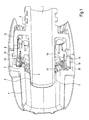
- the plug-in fitting initially comprises a main body 3, which is provided with a through-passage 1. On the main body 3, as shown in Figs. 1 and 2, a Pipe socket 2 attached, which is sealed by means of additional O-rings.
- the front end of the pipe socket 2 is widened like a cone and has a helix or helical coil 9, which facilitates the screwing of a tube 6 and additionally prevents the tube from slipping off.
- the plug-in fitting according to the invention further comprises an outer sleeve 4, which is provided in the embodiment shown in FIGS. 1 and 2 with an outer corrugation.
- the outer sleeve 4 is rotatably mounted on the base body 3, for which purpose an intermediate ring 12 and a bearing ring 13, designed as a snap connection, are provided.
- annular space 5 is formed, in which the tube 6 is inserted.
- annular latching device 7 which comprises a plurality of ratchet teeth 10.
- a securing element 8 is provided, which has a slot 14 or slot-shaped recesses, in which in the unassembled state of the tube 6, the biasing teeth 19 of the locking device 7 is arranged and thus the locking teeth 10 are biased.
- This state is shown in the upper part of FIG. 1.
- the locking teeth 10 are thus biased radially outward, at a release beat this, as shown in simplified form in Fig. 2, radially inward and thus reach against the surface of the tube (see assembled state Fig. 2).
- the ratchet teeth and biasing elements of the locking device 7 are alternating alternate to obtain the best preload of the ratchet teeth. It is also sufficient according to the invention if only a few of these ratchet teeth are preloaded.
- the locking device 7 is constructed so that it comprises a support ring 17 which is provided with support legs 18 which are integrally formed therewith and at an angle from its outer periphery extend from 90 ° to the plane of the carrier ring 17.
- the already mentioned locking teeth 10 are provided, which are provided with a sharp, cutting edge and claw into the surface of the tube 6.
- a biasing tooth 19 is provided in each case, which serves for biasing the latching device 7 (see FIG. 1).
- the biasing tooth 19 is bent radially outward and inserted into the slot 14 of the securing element 8.
- the locking teeth 10 themselves are also moved radially outward to the extent that insertion of the tube 6 is possible.
- the preload teeth 19 Upon release of the preload teeth 19 by displacement of the securing element 8 thus also the locking teeth 10 strike against the surface of the tube 6 and lead to the described fuse and Verkrallung.
- the biasing teeth 19 generate the described acoustic click signal when the fuse element 8 is moved and the locking device 7 releases.
- the pipe Upon insertion of the pipe into the ready-to-assemble, prestressed state of the push-fit fitting according to FIG. 1, the pipe is thus initially applied and expanded by turning the entire push-fit fitting onto the pipe socket 2.
- the tube 6 touches the securing element 8 and moves it in the axial direction to the rear. This results in a release of the biasing teeth 19 from the slot 14th
- FIG. 2 in the lower half shows that the outer sleeve 4 is provided on the inside with at least one, preferably with a plurality of symmetrically arranged grooves 15 in which a jaw or abutment surface 16 of the securing element 8 engages in the non-displaced state (lower Half of the figure of FIG. 1) to ensure a rotationally fixed coupling between the outer sleeve 4 and the securing element 8 and thus also the base body 3.
- the rotation of the outer sleeve 4 is released, so that it can be rotated arbitrarily, without rotation of the body 3 and thus the plug fitting itself.
- unintentional unscrewing of the pipe is not possible.
- a safe installation of the tube 6 is illustrated.
Landscapes
- Engineering & Computer Science (AREA)
- General Engineering & Computer Science (AREA)
- Mechanical Engineering (AREA)
- Quick-Acting Or Multi-Walled Pipe Joints (AREA)
- Details Of Connecting Devices For Male And Female Coupling (AREA)
Applications Claiming Priority (1)
| Application Number | Priority Date | Filing Date | Title |
|---|---|---|---|
| DE102005034181A DE102005034181B3 (de) | 2005-07-21 | 2005-07-21 | Steckfitting |
Publications (3)
| Publication Number | Publication Date |
|---|---|
| EP1746329A2 true EP1746329A2 (fr) | 2007-01-24 |
| EP1746329A3 EP1746329A3 (fr) | 2009-07-22 |
| EP1746329B1 EP1746329B1 (fr) | 2011-11-23 |
Family
ID=37101844
Family Applications (1)
| Application Number | Title | Priority Date | Filing Date |
|---|---|---|---|
| EP06012888A Not-in-force EP1746329B1 (fr) | 2005-07-21 | 2006-06-22 | Connecteur enfichable |
Country Status (4)
| Country | Link |
|---|---|
| EP (1) | EP1746329B1 (fr) |
| AT (1) | ATE534861T1 (fr) |
| DE (1) | DE102005034181B3 (fr) |
| ES (1) | ES2375972T3 (fr) |
Cited By (1)
| Publication number | Priority date | Publication date | Assignee | Title |
|---|---|---|---|---|
| CN102317671A (zh) * | 2009-01-12 | 2012-01-11 | 韦文有限公司 | 具有改进的夹持组件的推入配合式管连接器 |
Families Citing this family (1)
| Publication number | Priority date | Publication date | Assignee | Title |
|---|---|---|---|---|
| DE102008019979B3 (de) * | 2008-04-21 | 2009-10-01 | Futuree Fuel Cell Solutions Gmbh | Energieversorgungsmodul und Stromschrank |
Family Cites Families (4)
| Publication number | Priority date | Publication date | Assignee | Title |
|---|---|---|---|---|
| FR2479406B1 (fr) * | 1980-03-28 | 1985-08-23 | Legris | Raccords instantanes pour tubes nus et lisses |
| JP2001208266A (ja) * | 2000-01-20 | 2001-08-03 | Nippon Kokan Pipe Fittings Mfg Co Ltd | 差込み式管継手 |
| JP4676664B2 (ja) * | 2001-09-28 | 2011-04-27 | 株式会社タブチ | 管継手 |
| JP4121299B2 (ja) * | 2002-04-22 | 2008-07-23 | 株式会社オンダ製作所 | 継手 |
-
2005
- 2005-07-21 DE DE102005034181A patent/DE102005034181B3/de not_active Expired - Fee Related
-
2006
- 2006-06-22 ES ES06012888T patent/ES2375972T3/es active Active
- 2006-06-22 AT AT06012888T patent/ATE534861T1/de active
- 2006-06-22 EP EP06012888A patent/EP1746329B1/fr not_active Not-in-force
Cited By (1)
| Publication number | Priority date | Publication date | Assignee | Title |
|---|---|---|---|---|
| CN102317671A (zh) * | 2009-01-12 | 2012-01-11 | 韦文有限公司 | 具有改进的夹持组件的推入配合式管连接器 |
Also Published As
| Publication number | Publication date |
|---|---|
| ATE534861T1 (de) | 2011-12-15 |
| DE102005034181B3 (de) | 2007-03-08 |
| EP1746329B1 (fr) | 2011-11-23 |
| ES2375972T3 (es) | 2012-03-07 |
| EP1746329A3 (fr) | 2009-07-22 |
Similar Documents
| Publication | Publication Date | Title |
|---|---|---|
| DE69230338T2 (de) | Rohrkupplung | |
| DE3873033T2 (de) | Bewegliche verbindung fuer rohrfoermige leitungen. | |
| EP2864685B1 (fr) | Dispositif de raccordement pour conduites | |
| DE19828059C2 (de) | Anschlußarmatur mit einem durch Schlitze in Haltezungen aufgeteilten Befestigungsvorsprung | |
| DE3815168C2 (fr) | ||
| EP2088357A2 (fr) | Liaison indissoluble d'un raccord, d'une douille et d'un tuyau et raccord pour conduites de fluide et douille pour conduites de fluide | |
| DE19607784B4 (de) | Klemmverschraubung | |
| DE2309398B2 (de) | Anordnung für die Axialhalterung eines homokinetischen Gelenks | |
| WO2013020637A2 (fr) | Dispositif de raccordement permettant de raccorder une conduite de fluides | |
| EP0327080A1 (fr) | Raccord pour tuyau | |
| DE60010696T2 (de) | Schnellrohrkupplung | |
| EP1219883A2 (fr) | Dispositif de raccordement | |
| EP1326045B1 (fr) | Connecteur pour au moins une section de tuyaux et procédé de fixation d'un tel connecteur | |
| DE9315601U1 (de) | Rohrverschraubung mit einer Stützhülse und einer innenseitig konischen Erweiterung der Stützhülse | |
| EP1746329B1 (fr) | Connecteur enfichable | |
| DE29811259U1 (de) | Anschlußarmatur mit einem durch Schlitze in Haltezungen aufgeteilten Befestigungsvorsprung | |
| EP2366932A1 (fr) | Raccord par mandrinage et connexion entre un raccord par mandrinage et un tuyau | |
| EP0687848A1 (fr) | Raccord notamment pour dispositifs sanitaires et d'alimentation, tuyaux ou similaire | |
| EP1394461B1 (fr) | Bague à fermeture pour un raccord mâle et femelle pour des tubes | |
| DE202009004737U1 (de) | Rohrverbinder | |
| AT18336U1 (de) | Anschlussstück für Schläuche | |
| EP3404777A1 (fr) | Raccordement d'appareil | |
| EP1106886A2 (fr) | Dispositif pour la connexion de deux éléments | |
| EP4119737A1 (fr) | Dispositif de retenue en particulier pour l'évacuation des eaux des toitures plates | |
| DE2738454C3 (de) | Lösbare Muffensteckverbindung |
Legal Events
| Date | Code | Title | Description |
|---|---|---|---|
| PUAI | Public reference made under article 153(3) epc to a published international application that has entered the european phase |
Free format text: ORIGINAL CODE: 0009012 |
|
| AK | Designated contracting states |
Kind code of ref document: A2 Designated state(s): AT BE BG CH CY CZ DE DK EE ES FI FR GB GR HU IE IS IT LI LT LU LV MC NL PL PT RO SE SI SK TR |
|
| AX | Request for extension of the european patent |
Extension state: AL BA HR MK YU |
|
| PUAL | Search report despatched |
Free format text: ORIGINAL CODE: 0009013 |
|
| AK | Designated contracting states |
Kind code of ref document: A3 Designated state(s): AT BE BG CH CY CZ DE DK EE ES FI FR GB GR HU IE IS IT LI LT LU LV MC NL PL PT RO SE SI SK TR |
|
| AX | Request for extension of the european patent |
Extension state: AL BA HR MK RS |
|
| 17P | Request for examination filed |
Effective date: 20091119 |
|
| AKX | Designation fees paid |
Designated state(s): AT DE ES IT |
|
| GRAP | Despatch of communication of intention to grant a patent |
Free format text: ORIGINAL CODE: EPIDOSNIGR1 |
|
| GRAS | Grant fee paid |
Free format text: ORIGINAL CODE: EPIDOSNIGR3 |
|
| GRAA | (expected) grant |
Free format text: ORIGINAL CODE: 0009210 |
|
| AK | Designated contracting states |
Kind code of ref document: B1 Designated state(s): AT DE ES IT |
|
| REG | Reference to a national code |
Ref country code: DE Ref legal event code: R096 Ref document number: 502006010624 Country of ref document: DE Effective date: 20120119 |
|
| REG | Reference to a national code |
Ref country code: ES Ref legal event code: FG2A Ref document number: 2375972 Country of ref document: ES Kind code of ref document: T3 Effective date: 20120307 |
|
| PLBE | No opposition filed within time limit |
Free format text: ORIGINAL CODE: 0009261 |
|
| STAA | Information on the status of an ep patent application or granted ep patent |
Free format text: STATUS: NO OPPOSITION FILED WITHIN TIME LIMIT |
|
| 26N | No opposition filed |
Effective date: 20120824 |
|
| REG | Reference to a national code |
Ref country code: DE Ref legal event code: R097 Ref document number: 502006010624 Country of ref document: DE Effective date: 20120824 |
|
| PGFP | Annual fee paid to national office [announced via postgrant information from national office to epo] |
Ref country code: ES Payment date: 20140618 Year of fee payment: 9 Ref country code: AT Payment date: 20140618 Year of fee payment: 9 Ref country code: DE Payment date: 20140630 Year of fee payment: 9 Ref country code: IT Payment date: 20140627 Year of fee payment: 9 |
|
| REG | Reference to a national code |
Ref country code: DE Ref legal event code: R119 Ref document number: 502006010624 Country of ref document: DE |
|
| PG25 | Lapsed in a contracting state [announced via postgrant information from national office to epo] |
Ref country code: IT Free format text: LAPSE BECAUSE OF NON-PAYMENT OF DUE FEES Effective date: 20150622 |
|
| REG | Reference to a national code |
Ref country code: AT Ref legal event code: MM01 Ref document number: 534861 Country of ref document: AT Kind code of ref document: T Effective date: 20150622 |
|
| PG25 | Lapsed in a contracting state [announced via postgrant information from national office to epo] |
Ref country code: DE Free format text: LAPSE BECAUSE OF NON-PAYMENT OF DUE FEES Effective date: 20160101 |
|
| PG25 | Lapsed in a contracting state [announced via postgrant information from national office to epo] |
Ref country code: AT Free format text: LAPSE BECAUSE OF NON-PAYMENT OF DUE FEES Effective date: 20150622 |
|
| REG | Reference to a national code |
Ref country code: ES Ref legal event code: FD2A Effective date: 20160801 |
|
| PG25 | Lapsed in a contracting state [announced via postgrant information from national office to epo] |
Ref country code: ES Free format text: LAPSE BECAUSE OF NON-PAYMENT OF DUE FEES Effective date: 20150623 |