EP2366932A1 - Raccord par mandrinage et connexion entre un raccord par mandrinage et un tuyau - Google Patents
Raccord par mandrinage et connexion entre un raccord par mandrinage et un tuyau Download PDFInfo
- Publication number
- EP2366932A1 EP2366932A1 EP10405055A EP10405055A EP2366932A1 EP 2366932 A1 EP2366932 A1 EP 2366932A1 EP 10405055 A EP10405055 A EP 10405055A EP 10405055 A EP10405055 A EP 10405055A EP 2366932 A1 EP2366932 A1 EP 2366932A1
- Authority
- EP
- European Patent Office
- Prior art keywords
- ring
- claw
- plug
- sealing ring
- tube
- Prior art date
- Legal status (The legal status is an assumption and is not a legal conclusion. Google has not performed a legal analysis and makes no representation as to the accuracy of the status listed.)
- Granted
Links
- 210000000078 claw Anatomy 0.000 claims abstract description 76
- 238000007789 sealing Methods 0.000 claims description 41
- 238000003780 insertion Methods 0.000 claims description 5
- 230000037431 insertion Effects 0.000 claims description 5
- 150000001875 compounds Chemical class 0.000 claims description 2
- 210000002105 tongue Anatomy 0.000 description 6
- 244000089486 Phragmites australis subsp australis Species 0.000 description 3
- 238000004519 manufacturing process Methods 0.000 description 3
- 239000013013 elastic material Substances 0.000 description 2
- 239000002184 metal Substances 0.000 description 2
- 239000002131 composite material Substances 0.000 description 1
- 230000001419 dependent effect Effects 0.000 description 1
- 239000000463 material Substances 0.000 description 1
- 238000000034 method Methods 0.000 description 1
- 238000002360 preparation method Methods 0.000 description 1
- 238000004080 punching Methods 0.000 description 1
Images

Classifications
-
- F—MECHANICAL ENGINEERING; LIGHTING; HEATING; WEAPONS; BLASTING
- F16—ENGINEERING ELEMENTS AND UNITS; GENERAL MEASURES FOR PRODUCING AND MAINTAINING EFFECTIVE FUNCTIONING OF MACHINES OR INSTALLATIONS; THERMAL INSULATION IN GENERAL
- F16L—PIPES; JOINTS OR FITTINGS FOR PIPES; SUPPORTS FOR PIPES, CABLES OR PROTECTIVE TUBING; MEANS FOR THERMAL INSULATION IN GENERAL
- F16L37/00—Couplings of the quick-acting type
- F16L37/08—Couplings of the quick-acting type in which the connection between abutting or axially overlapping ends is maintained by locking members
- F16L37/084—Couplings of the quick-acting type in which the connection between abutting or axially overlapping ends is maintained by locking members combined with automatic locking
- F16L37/091—Couplings of the quick-acting type in which the connection between abutting or axially overlapping ends is maintained by locking members combined with automatic locking by means of a ring provided with teeth or fingers
-
- F—MECHANICAL ENGINEERING; LIGHTING; HEATING; WEAPONS; BLASTING
- F16—ENGINEERING ELEMENTS AND UNITS; GENERAL MEASURES FOR PRODUCING AND MAINTAINING EFFECTIVE FUNCTIONING OF MACHINES OR INSTALLATIONS; THERMAL INSULATION IN GENERAL
- F16L—PIPES; JOINTS OR FITTINGS FOR PIPES; SUPPORTS FOR PIPES, CABLES OR PROTECTIVE TUBING; MEANS FOR THERMAL INSULATION IN GENERAL
- F16L37/00—Couplings of the quick-acting type
- F16L37/08—Couplings of the quick-acting type in which the connection between abutting or axially overlapping ends is maintained by locking members
- F16L37/084—Couplings of the quick-acting type in which the connection between abutting or axially overlapping ends is maintained by locking members combined with automatic locking
- F16L37/0845—Couplings of the quick-acting type in which the connection between abutting or axially overlapping ends is maintained by locking members combined with automatic locking by means of retaining members associated with the packing member
Definitions
- the invention relates to a plug-in sleeve having a housing which has an opening at at least one end, in which a claw ring is arranged, which has a plurality of radially inwardly projecting claw elements with which an inserted into this opening end of a tube is fixed and with at least one sealing ring, which is also arranged in this opening and with which said end of the tube is sealable at its periphery relative to the housing.
- Such push-in sleeves are in sanitary engineering in numerous designs in use. They make it possible to connect a pipe with a second pipe or a sanitary article. The connection is made in a simple manner by the tube is inserted with the end to be connected in the opening of the socket.
- the compound can be solvable or insoluble. It is essential that the inserted tube is securely fixed in the socket and on the other hand sealed against the sleeve housing. Both functions should be ensured after insertion of the tube in the socket without further action.
- the cross section of the pipe or the pipe should not be limited by the plug-in sleeve. The plug-in sleeve should therefore only engage on the outside, but not in the tube.
- the WO 2009/051431 discloses a plug-in sleeve of the type mentioned.
- the claw ring consists here of a plurality of teeth which are mounted in a sleeve-shaped carrier.
- This carrier is coupled to the sleeve housing by against the retroactive force of a sleeve spring arranged in the coil spring up to a stop in the Sleeve housing is inserted.
- the teeth slide along a conical surface along the inside of the sleeve housing.
- the coil spring is arranged between two sealing rings and the claw ring.
- the invention has for its object to provide a plug-in socket of the type mentioned, which can be made easier and yet is reliable.
- the problem is solved in a generic plug-in sleeve characterized in that the sealing ring and the claw ring form a preassembled unit.
- the sealing ring and the claw ring are thus connected to each other and used as a unit in the opening of the housing or used.
- the sealing ring and the claw ring can be pre-assembled as a unit and used as such in said opening.
- the sealing ring and the claw ring thus form an assembly that can be used directly in the housing of the socket.
- a retaining ring is arranged between the claw ring and the sealing ring, which connects the sealing ring with the claw ring.
- the preparation is particularly simple when, according to a development of the invention, the sealing ring, the retaining ring and the claw ring are put together.
- the sealing ring, the retaining ring and the Krallring can thus be made separately and by plugging these are connected to said unit.
- the sealing ring, the retaining ring and the claw ring are each connected to each other with latching means. This allows a particularly simple connection of said rings to said assembly.
- the claw ring is axially limited slidably mounted on the retaining ring.
- the Claw ring are moved axially towards the retaining ring.
- the claw elements are then moved accordingly and pushed into a groove on the inside of the housing. If the tube is completely inserted into the housing, the claw elements are fixed in this groove. Since the claw elements are hooked on the outside of the tube in this, the pipe can not be pulled out of the housing of the socket.
- the production of the claw ring is particularly simple if, according to a development of the invention, the claw ring has at its periphery a plurality of segments, between each of which a claw element is mounted.
- each two adjacent segments are connected to one another with a web and that the claw elements are each mounted on one of these webs.
- the claw elements are in particular pivotally mounted on the claw ring or in each case on a web. When inserting the tube into the housing of the plug-in sleeve, these claw elements are pivoted and thereby anchored to the housing.
- the claw elements can be attached to the claw ring in a particularly simple and secure manner by attaching them.
- These claw elements are attached in particular to said webs. Preferably, they are placed radially from the inside on these webs.
- Such claw elements can for example be produced particularly easily by punching from sheet metal.
- the sealing ring has locking cams, with which it is connected to the retaining ring.
- These locking cams allow a particularly simple and secure connection of the sealing ring with the retaining ring.
- the locking cams are preferably formed on the sealing ring and made of rubber-elastic material.
- the locking cams form axial spring elements for the claw ring.
- the locking cams are preferably designed so that they engage in the retaining ring.
- An annular carrier of the claw ring preferably also engages in the retaining ring and can be clamped against said locking cams.
- a separate spring element, such as a coil spring can be avoided.
- the said unit may be in this Case then be made particularly compact and with few items.
- said unit is releasably held with an annular retaining element in said opening.
- the retaining element is in this case, for example, locked in a groove of the housing.
- the retaining ring is detachable, so that the unit can be removed.
- the invention also relates to a connection between a plug-in sleeve and a pipe.
- the tube inserted into the plug-in sleeve viewed in the insertion direction, first passes through the claw ring and then the sealing ring.
- the unit also has a retaining ring, the tube in the direction of insertion first reaches through the claw ring, then the retaining ring and finally the sealing ring.
- the sealing ring and the sealing means are in this case preferably braced against each other in the axial direction. The tension is maintained by said locking cam of the sealing ring.
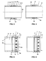
- the plug-in sleeve 1 has according to the FIGS. 3 to 6 a housing 3, which is sleeve-shaped and has a passage 10. At least one end of the housing 3, a receiving socket 4 is arranged, which forms an opening 5, in which a tube 8 is inserted.
- the receiving socket 4 has an outer diameter which is slightly larger than the outer diameter of the housing 3 on an outer side 6.
- the inner diameter of the receiving socket 4, however, is slightly larger than the diameter of an inner side 7.
- an insert 2 is inserted, the inside is substantially aligned with said inner side 7.
- This insert 2 is held in the receiving socket 4 with a holding element 29 which is engaged in a groove 11 of the receiving socket 4.
- a shoulder 30 on the inside of the receiving nozzle 4 forms an axial stop for the insert 2.
- the holding element 29 could also be designed as a union nut, which is screwed onto the receiving socket 4.
- the insert 2 consists of a sealing ring 14, a retaining ring 17 and a claw ring 22. These three rings are connected together and form a structural unit.
- the sealing ring 14 engages in a groove 13 on the inside of the receiving nozzle 4.
- this unit 2 is inserted into the opening of the receiving socket 4 and finally secured with the retaining element 29.
- the sealing ring 14 has on an annular inner side 31 a plurality of axially projecting locking cams 15. In the connected state, these locking cams 15 each engage in an opening 19 of the retaining ring 17. These openings 19 each extend in the axial direction through the retaining ring 17 therethrough.
- the openings 19 are thus at the in Fig. 2 not shown back side open.
- the locking cams 15 are like the rest of the sealing ring 14 made of a rubber-elastic material. In order to connect the sealing ring 14 with the retaining ring 17, these two parts must therefore only be plugged together. The locking cam 15 then engage each detent in one of the openings 19 a.
- the openings 19 are each connected on the outside with the recesses 18.
- the retaining ring 17 is also locked to the claw ring 22.
- an annular carrier 27 of the claw ring 22 has a plurality of axially extending tongues 26, which are respectively engaged in one of the openings 19. In the openings 19 thus engages from the one side a locking cam 15 and from the other side a tongue 26 a.
- the retaining ring 17 and the claw ring 22 can thus also be connected by simply plugging together.
- the claw ring 22 is connected to the retaining ring 17 so that they are limited in the axial direction against each other.
- the corresponding path is determined by the length of the tongues 26 and is usually a few millimeters.
- lie in the recesses 18 each have a locking cam 15 and a tongue 26 opposite. If the claw ring 22 in the in Fig. 1 shown position axially against the retaining ring 17 moves toward, so the rubber-elastic locking cams 15 are stretched by the tongues 26 in the axial direction.
- the carrier 27 of the claw ring 22 has a plurality of segments 23, which are connected to each other via webs 24.
- the webs 24 each bridge a gap 28 of the carrier 27, in particular the Fig. 2 shows.
- the claw ring 22 has claw elements 25 which are each pivotally mounted on one of the webs 24.
- the claw elements 25 each have a recess 25a, in each of which a web 24 engages.
- the claw elements 25 may be latched onto the webs 24, for example.
- the claw elements 25 are inserted from the inside into the gaps 28.
- the claw elements 25 also have on the inside two serrations 25b. These serrations 25b each extend according to the FIGS. 5 and 6 inclined to the axis 32 of the housing 3.
- the claw elements 25 each have a pivot axis 33 (FIG. Fig. 3 ) which extends in the corresponding web 24, in the circumferential direction of the claw ring 22 and which, as can be seen, has a clearance to the corresponding teeth 25b.
- the axes 33 are arranged comparatively radially far outside within the receiving socket 4.
- the tube 8 also passes through the sealing ring 14, which bears elastically with a sealing lip 16 on the outside 9 of the tube 8.
- the movement of the tube 8 may be limited by a stop, not shown here. Due to the tension of the rubber-elastic locking cams 15, the claw elements 25 are pressed with the teeth 25 b on the outside 9 of the tube 8. The serrations 25b dig into the outside 9 of the tube 8 and thereby fix the tube 8 in the socket 1. A pulling out of the tube 8 from the socket 1 is no longer possible.
- the connection is basically not solvable.
- the tube 8 is in particular a metal tube. But here are also pipes made of other materials and composite pipes conceivable.
Landscapes
- Engineering & Computer Science (AREA)
- General Engineering & Computer Science (AREA)
- Mechanical Engineering (AREA)
- Quick-Acting Or Multi-Walled Pipe Joints (AREA)
Priority Applications (1)
| Application Number | Priority Date | Filing Date | Title |
|---|---|---|---|
| EP10405055.4A EP2366932B1 (fr) | 2010-03-17 | 2010-03-17 | Raccord par mandrinage et connexion entre un raccord par mandrinage et un tuyau |
Applications Claiming Priority (1)
| Application Number | Priority Date | Filing Date | Title |
|---|---|---|---|
| EP10405055.4A EP2366932B1 (fr) | 2010-03-17 | 2010-03-17 | Raccord par mandrinage et connexion entre un raccord par mandrinage et un tuyau |
Publications (2)
| Publication Number | Publication Date |
|---|---|
| EP2366932A1 true EP2366932A1 (fr) | 2011-09-21 |
| EP2366932B1 EP2366932B1 (fr) | 2017-06-28 |
Family
ID=43034628
Family Applications (1)
| Application Number | Title | Priority Date | Filing Date |
|---|---|---|---|
| EP10405055.4A Not-in-force EP2366932B1 (fr) | 2010-03-17 | 2010-03-17 | Raccord par mandrinage et connexion entre un raccord par mandrinage et un tuyau |
Country Status (1)
| Country | Link |
|---|---|
| EP (1) | EP2366932B1 (fr) |
Cited By (3)
| Publication number | Priority date | Publication date | Assignee | Title |
|---|---|---|---|---|
| KR20160082923A (ko) * | 2015-01-01 | 2016-07-11 | (주)웨지엔 | 회전쐐기를 이용한 파이프 연결장치 |
| CN106287071A (zh) * | 2016-10-20 | 2017-01-04 | 曾庆涛 | 工业废液再利用装置及其使用的管道连接装置 |
| CN111853385A (zh) * | 2020-08-26 | 2020-10-30 | 江苏领嘉科技有限公司 | 一种钝齿环、高耐压压接连接金属管的管件及其加工方法 |
Citations (6)
| Publication number | Priority date | Publication date | Assignee | Title |
|---|---|---|---|---|
| GB2160279A (en) * | 1984-06-13 | 1985-12-18 | Hawke Cable Glands Ltd | Releasable pipe coupling |
| USRE36630E (en) * | 1992-01-17 | 2000-03-28 | Senior Engineering Investments Ag | Thermal isolation coupling system |
| DE10162658A1 (de) * | 2001-12-20 | 2003-07-10 | Festo Ag & Co | Anschlussstück für Fluidleitungen und damit ausgestattetes fluidtechnisches Gerät |
| US20060265852A1 (en) * | 2001-01-19 | 2006-11-30 | Victaulic Company | Triple-expanded mechanical pipe coupling derived from a standard fitting |
| WO2009017587A1 (fr) * | 2007-07-30 | 2009-02-05 | Williams Robert M | Appareil, outils et procédés de raccordement d'un tube pouvant être soudé sans solvant à un tube pouvant être soudé par solvant et raccords |
| WO2009051431A2 (fr) | 2007-10-18 | 2009-04-23 | Jointop Co., Ltd. | Appareil, procédé de raccordement de tuyaux et procédé de fabrication de mâchoire de mâchoire de serrage |
-
2010
- 2010-03-17 EP EP10405055.4A patent/EP2366932B1/fr not_active Not-in-force
Patent Citations (6)
| Publication number | Priority date | Publication date | Assignee | Title |
|---|---|---|---|---|
| GB2160279A (en) * | 1984-06-13 | 1985-12-18 | Hawke Cable Glands Ltd | Releasable pipe coupling |
| USRE36630E (en) * | 1992-01-17 | 2000-03-28 | Senior Engineering Investments Ag | Thermal isolation coupling system |
| US20060265852A1 (en) * | 2001-01-19 | 2006-11-30 | Victaulic Company | Triple-expanded mechanical pipe coupling derived from a standard fitting |
| DE10162658A1 (de) * | 2001-12-20 | 2003-07-10 | Festo Ag & Co | Anschlussstück für Fluidleitungen und damit ausgestattetes fluidtechnisches Gerät |
| WO2009017587A1 (fr) * | 2007-07-30 | 2009-02-05 | Williams Robert M | Appareil, outils et procédés de raccordement d'un tube pouvant être soudé sans solvant à un tube pouvant être soudé par solvant et raccords |
| WO2009051431A2 (fr) | 2007-10-18 | 2009-04-23 | Jointop Co., Ltd. | Appareil, procédé de raccordement de tuyaux et procédé de fabrication de mâchoire de mâchoire de serrage |
Cited By (4)
| Publication number | Priority date | Publication date | Assignee | Title |
|---|---|---|---|---|
| KR20160082923A (ko) * | 2015-01-01 | 2016-07-11 | (주)웨지엔 | 회전쐐기를 이용한 파이프 연결장치 |
| CN106287071A (zh) * | 2016-10-20 | 2017-01-04 | 曾庆涛 | 工业废液再利用装置及其使用的管道连接装置 |
| CN106287071B (zh) * | 2016-10-20 | 2023-09-12 | 南京宇清环境科技有限公司 | 工业废液再利用装置及其使用的管道连接装置 |
| CN111853385A (zh) * | 2020-08-26 | 2020-10-30 | 江苏领嘉科技有限公司 | 一种钝齿环、高耐压压接连接金属管的管件及其加工方法 |
Also Published As
| Publication number | Publication date |
|---|---|
| EP2366932B1 (fr) | 2017-06-28 |
Similar Documents
| Publication | Publication Date | Title |
|---|---|---|
| DE3873033T2 (de) | Bewegliche verbindung fuer rohrfoermige leitungen. | |
| DE69920059T2 (de) | Kunstharzrohrkupplung mit einem Verstärkungsring | |
| EP2088357B1 (fr) | Liaison indissoluble d'un raccord, d'une douille et d'un tuyau et raccord pour conduites de fluide et douille pour conduites de fluide | |
| EP2898251B1 (fr) | Système modulaire avec un dispositif de raccordement destiné à plusieurs conduites de fluide differentes | |
| DE112006004024B4 (de) | Montagewerkzeug für eine Anschlussvorrichtung für Medienleitungen | |
| EP2712413B1 (fr) | Dispositif de raccordement permettant de raccorder une conduite de fluides | |
| EP1781979A1 (fr) | Raccord emboitable pour conduites fluidiques | |
| EP2233814A1 (fr) | Dispositif de connexion amovible doté d'une extrémité d'une conduite de type tubulaire, notamment connecteur rapide de tuyau | |
| DE10347927B4 (de) | Verfahren und Vorrichtung zur Herstellung einer Rohrpressverbindung an einer Steckverbindung | |
| WO1988006252A2 (fr) | Raccord enfichable detachable pour tubulures | |
| EP2366932B1 (fr) | Raccord par mandrinage et connexion entre un raccord par mandrinage et un tuyau | |
| DE19736765A1 (de) | Einsteckkupplung | |
| EP2369215A1 (fr) | Connecteur à fiches | |
| DE102005058161B4 (de) | Schnellverschluss für den Installationsbereich | |
| EP2864682B1 (fr) | Raccord de tuyau | |
| DE9007056U1 (de) | Verbindungselement für Wellrohre und Schläuche | |
| DE102010012523A1 (de) | Vorrichtung zum Verbinden mit einer Rohr- oder Schlauchleitung, insbesondere Klemmringverschraubung | |
| EP1930642A2 (fr) | Elément de retenue | |
| EP1418378B1 (fr) | Element pour la fixation d'une buse à une conduite de fluide | |
| DE202009005674U1 (de) | Vorrichtung zum schwenkbaren Verbinden von zwei Leitungsabschnitten | |
| DE202005004524U1 (de) | Steckverbinder | |
| DE202009004737U1 (de) | Rohrverbinder | |
| DE102006026162B4 (de) | Anschlussvorrichtung für Medienleitungen | |
| DE19909394B4 (de) | Lösbare Steckverbindung für den Anschluß von Rohrleitungen | |
| DE29514822U1 (de) | Kupplungsteil |
Legal Events
| Date | Code | Title | Description |
|---|---|---|---|
| PUAI | Public reference made under article 153(3) epc to a published international application that has entered the european phase |
Free format text: ORIGINAL CODE: 0009012 |
|
| AK | Designated contracting states |
Kind code of ref document: A1 Designated state(s): AT BE BG CH CY CZ DE DK EE ES FI FR GB GR HR HU IE IS IT LI LT LU LV MC MK MT NL NO PL PT RO SE SI SK SM TR |
|
| AX | Request for extension of the european patent |
Extension state: AL BA ME RS |
|
| 17P | Request for examination filed |
Effective date: 20111027 |
|
| GRAP | Despatch of communication of intention to grant a patent |
Free format text: ORIGINAL CODE: EPIDOSNIGR1 |
|
| GRAJ | Information related to disapproval of communication of intention to grant by the applicant or resumption of examination proceedings by the epo deleted |
Free format text: ORIGINAL CODE: EPIDOSDIGR1 |
|
| RIC1 | Information provided on ipc code assigned before grant |
Ipc: F16L 37/084 20060101AFI20161129BHEP Ipc: F16L 37/091 20060101ALI20161129BHEP |
|
| GRAP | Despatch of communication of intention to grant a patent |
Free format text: ORIGINAL CODE: EPIDOSNIGR1 |
|
| INTG | Intention to grant announced |
Effective date: 20161223 |
|
| INTG | Intention to grant announced |
Effective date: 20170113 |
|
| GRAS | Grant fee paid |
Free format text: ORIGINAL CODE: EPIDOSNIGR3 |
|
| GRAA | (expected) grant |
Free format text: ORIGINAL CODE: 0009210 |
|
| AK | Designated contracting states |
Kind code of ref document: B1 Designated state(s): AT BE BG CH CY CZ DE DK EE ES FI FR GB GR HR HU IE IS IT LI LT LU LV MC MK MT NL NO PL PT RO SE SI SK SM TR |
|
| REG | Reference to a national code |
Ref country code: GB Ref legal event code: FG4D Free format text: NOT ENGLISH |
|
| REG | Reference to a national code |
Ref country code: CH Ref legal event code: EP |
|
| REG | Reference to a national code |
Ref country code: AT Ref legal event code: REF Ref document number: 905175 Country of ref document: AT Kind code of ref document: T Effective date: 20170715 |
|
| REG | Reference to a national code |
Ref country code: IE Ref legal event code: FG4D Free format text: LANGUAGE OF EP DOCUMENT: GERMAN |
|
| REG | Reference to a national code |
Ref country code: DE Ref legal event code: R096 Ref document number: 502010013804 Country of ref document: DE |
|
| REG | Reference to a national code |
Ref country code: CH Ref legal event code: NV Representative=s name: ISLER AND PEDRAZZINI AG, CH |
|
| PG25 | Lapsed in a contracting state [announced via postgrant information from national office to epo] |
Ref country code: HR Free format text: LAPSE BECAUSE OF FAILURE TO SUBMIT A TRANSLATION OF THE DESCRIPTION OR TO PAY THE FEE WITHIN THE PRESCRIBED TIME-LIMIT Effective date: 20170628 Ref country code: FI Free format text: LAPSE BECAUSE OF FAILURE TO SUBMIT A TRANSLATION OF THE DESCRIPTION OR TO PAY THE FEE WITHIN THE PRESCRIBED TIME-LIMIT Effective date: 20170628 Ref country code: GR Free format text: LAPSE BECAUSE OF FAILURE TO SUBMIT A TRANSLATION OF THE DESCRIPTION OR TO PAY THE FEE WITHIN THE PRESCRIBED TIME-LIMIT Effective date: 20170929 Ref country code: NO Free format text: LAPSE BECAUSE OF FAILURE TO SUBMIT A TRANSLATION OF THE DESCRIPTION OR TO PAY THE FEE WITHIN THE PRESCRIBED TIME-LIMIT Effective date: 20170928 Ref country code: LT Free format text: LAPSE BECAUSE OF FAILURE TO SUBMIT A TRANSLATION OF THE DESCRIPTION OR TO PAY THE FEE WITHIN THE PRESCRIBED TIME-LIMIT Effective date: 20170628 |
|
| REG | Reference to a national code |
Ref country code: NL Ref legal event code: MP Effective date: 20170628 |
|
| REG | Reference to a national code |
Ref country code: LT Ref legal event code: MG4D |
|
| PG25 | Lapsed in a contracting state [announced via postgrant information from national office to epo] |
Ref country code: BG Free format text: LAPSE BECAUSE OF FAILURE TO SUBMIT A TRANSLATION OF THE DESCRIPTION OR TO PAY THE FEE WITHIN THE PRESCRIBED TIME-LIMIT Effective date: 20170928 Ref country code: NL Free format text: LAPSE BECAUSE OF FAILURE TO SUBMIT A TRANSLATION OF THE DESCRIPTION OR TO PAY THE FEE WITHIN THE PRESCRIBED TIME-LIMIT Effective date: 20170628 Ref country code: LV Free format text: LAPSE BECAUSE OF FAILURE TO SUBMIT A TRANSLATION OF THE DESCRIPTION OR TO PAY THE FEE WITHIN THE PRESCRIBED TIME-LIMIT Effective date: 20170628 Ref country code: SE Free format text: LAPSE BECAUSE OF FAILURE TO SUBMIT A TRANSLATION OF THE DESCRIPTION OR TO PAY THE FEE WITHIN THE PRESCRIBED TIME-LIMIT Effective date: 20170628 |
|
| PG25 | Lapsed in a contracting state [announced via postgrant information from national office to epo] |
Ref country code: RO Free format text: LAPSE BECAUSE OF FAILURE TO SUBMIT A TRANSLATION OF THE DESCRIPTION OR TO PAY THE FEE WITHIN THE PRESCRIBED TIME-LIMIT Effective date: 20170628 Ref country code: EE Free format text: LAPSE BECAUSE OF FAILURE TO SUBMIT A TRANSLATION OF THE DESCRIPTION OR TO PAY THE FEE WITHIN THE PRESCRIBED TIME-LIMIT Effective date: 20170628 Ref country code: SK Free format text: LAPSE BECAUSE OF FAILURE TO SUBMIT A TRANSLATION OF THE DESCRIPTION OR TO PAY THE FEE WITHIN THE PRESCRIBED TIME-LIMIT Effective date: 20170628 Ref country code: CZ Free format text: LAPSE BECAUSE OF FAILURE TO SUBMIT A TRANSLATION OF THE DESCRIPTION OR TO PAY THE FEE WITHIN THE PRESCRIBED TIME-LIMIT Effective date: 20170628 |
|
| PG25 | Lapsed in a contracting state [announced via postgrant information from national office to epo] |
Ref country code: SM Free format text: LAPSE BECAUSE OF FAILURE TO SUBMIT A TRANSLATION OF THE DESCRIPTION OR TO PAY THE FEE WITHIN THE PRESCRIBED TIME-LIMIT Effective date: 20170628 Ref country code: IS Free format text: LAPSE BECAUSE OF FAILURE TO SUBMIT A TRANSLATION OF THE DESCRIPTION OR TO PAY THE FEE WITHIN THE PRESCRIBED TIME-LIMIT Effective date: 20171028 Ref country code: PL Free format text: LAPSE BECAUSE OF FAILURE TO SUBMIT A TRANSLATION OF THE DESCRIPTION OR TO PAY THE FEE WITHIN THE PRESCRIBED TIME-LIMIT Effective date: 20170628 Ref country code: ES Free format text: LAPSE BECAUSE OF FAILURE TO SUBMIT A TRANSLATION OF THE DESCRIPTION OR TO PAY THE FEE WITHIN THE PRESCRIBED TIME-LIMIT Effective date: 20170628 |
|
| REG | Reference to a national code |
Ref country code: DE Ref legal event code: R097 Ref document number: 502010013804 Country of ref document: DE |
|
| PG25 | Lapsed in a contracting state [announced via postgrant information from national office to epo] |
Ref country code: DK Free format text: LAPSE BECAUSE OF FAILURE TO SUBMIT A TRANSLATION OF THE DESCRIPTION OR TO PAY THE FEE WITHIN THE PRESCRIBED TIME-LIMIT Effective date: 20170628 |
|
| PLBE | No opposition filed within time limit |
Free format text: ORIGINAL CODE: 0009261 |
|
| STAA | Information on the status of an ep patent application or granted ep patent |
Free format text: STATUS: NO OPPOSITION FILED WITHIN TIME LIMIT |
|
| 26N | No opposition filed |
Effective date: 20180329 |
|
| PG25 | Lapsed in a contracting state [announced via postgrant information from national office to epo] |
Ref country code: SI Free format text: LAPSE BECAUSE OF FAILURE TO SUBMIT A TRANSLATION OF THE DESCRIPTION OR TO PAY THE FEE WITHIN THE PRESCRIBED TIME-LIMIT Effective date: 20170628 |
|
| PG25 | Lapsed in a contracting state [announced via postgrant information from national office to epo] |
Ref country code: MT Free format text: LAPSE BECAUSE OF FAILURE TO SUBMIT A TRANSLATION OF THE DESCRIPTION OR TO PAY THE FEE WITHIN THE PRESCRIBED TIME-LIMIT Effective date: 20170628 |
|
| GBPC | Gb: european patent ceased through non-payment of renewal fee |
Effective date: 20180317 |
|
| PG25 | Lapsed in a contracting state [announced via postgrant information from national office to epo] |
Ref country code: MC Free format text: LAPSE BECAUSE OF FAILURE TO SUBMIT A TRANSLATION OF THE DESCRIPTION OR TO PAY THE FEE WITHIN THE PRESCRIBED TIME-LIMIT Effective date: 20170628 |
|
| REG | Reference to a national code |
Ref country code: BE Ref legal event code: MM Effective date: 20180331 |
|
| REG | Reference to a national code |
Ref country code: IE Ref legal event code: MM4A |
|
| PG25 | Lapsed in a contracting state [announced via postgrant information from national office to epo] |
Ref country code: LU Free format text: LAPSE BECAUSE OF NON-PAYMENT OF DUE FEES Effective date: 20180317 |
|
| PG25 | Lapsed in a contracting state [announced via postgrant information from national office to epo] |
Ref country code: IE Free format text: LAPSE BECAUSE OF NON-PAYMENT OF DUE FEES Effective date: 20180317 |
|
| PG25 | Lapsed in a contracting state [announced via postgrant information from national office to epo] |
Ref country code: GB Free format text: LAPSE BECAUSE OF NON-PAYMENT OF DUE FEES Effective date: 20180317 Ref country code: BE Free format text: LAPSE BECAUSE OF NON-PAYMENT OF DUE FEES Effective date: 20180331 |
|
| PG25 | Lapsed in a contracting state [announced via postgrant information from national office to epo] |
Ref country code: FR Free format text: LAPSE BECAUSE OF NON-PAYMENT OF DUE FEES Effective date: 20180331 |
|
| PG25 | Lapsed in a contracting state [announced via postgrant information from national office to epo] |
Ref country code: TR Free format text: LAPSE BECAUSE OF FAILURE TO SUBMIT A TRANSLATION OF THE DESCRIPTION OR TO PAY THE FEE WITHIN THE PRESCRIBED TIME-LIMIT Effective date: 20170628 |
|
| PG25 | Lapsed in a contracting state [announced via postgrant information from national office to epo] |
Ref country code: PT Free format text: LAPSE BECAUSE OF FAILURE TO SUBMIT A TRANSLATION OF THE DESCRIPTION OR TO PAY THE FEE WITHIN THE PRESCRIBED TIME-LIMIT Effective date: 20170628 Ref country code: HU Free format text: LAPSE BECAUSE OF FAILURE TO SUBMIT A TRANSLATION OF THE DESCRIPTION OR TO PAY THE FEE WITHIN THE PRESCRIBED TIME-LIMIT; INVALID AB INITIO Effective date: 20100317 |
|
| PG25 | Lapsed in a contracting state [announced via postgrant information from national office to epo] |
Ref country code: MK Free format text: LAPSE BECAUSE OF NON-PAYMENT OF DUE FEES Effective date: 20170628 Ref country code: CY Free format text: LAPSE BECAUSE OF FAILURE TO SUBMIT A TRANSLATION OF THE DESCRIPTION OR TO PAY THE FEE WITHIN THE PRESCRIBED TIME-LIMIT Effective date: 20170628 |
|
| PGFP | Annual fee paid to national office [announced via postgrant information from national office to epo] |
Ref country code: CH Payment date: 20210311 Year of fee payment: 12 Ref country code: IT Payment date: 20210323 Year of fee payment: 12 |
|
| PGFP | Annual fee paid to national office [announced via postgrant information from national office to epo] |
Ref country code: AT Payment date: 20210322 Year of fee payment: 12 Ref country code: DE Payment date: 20210319 Year of fee payment: 12 |
|
| REG | Reference to a national code |
Ref country code: DE Ref legal event code: R119 Ref document number: 502010013804 Country of ref document: DE |
|
| REG | Reference to a national code |
Ref country code: CH Ref legal event code: PL |
|
| REG | Reference to a national code |
Ref country code: AT Ref legal event code: MM01 Ref document number: 905175 Country of ref document: AT Kind code of ref document: T Effective date: 20220317 |
|
| PG25 | Lapsed in a contracting state [announced via postgrant information from national office to epo] |
Ref country code: LI Free format text: LAPSE BECAUSE OF NON-PAYMENT OF DUE FEES Effective date: 20220331 Ref country code: DE Free format text: LAPSE BECAUSE OF NON-PAYMENT OF DUE FEES Effective date: 20221001 Ref country code: CH Free format text: LAPSE BECAUSE OF NON-PAYMENT OF DUE FEES Effective date: 20220331 Ref country code: AT Free format text: LAPSE BECAUSE OF NON-PAYMENT OF DUE FEES Effective date: 20220317 |
|
| PG25 | Lapsed in a contracting state [announced via postgrant information from national office to epo] |
Ref country code: IT Free format text: LAPSE BECAUSE OF NON-PAYMENT OF DUE FEES Effective date: 20220317 |