EP1746363A2 - Récepteur solaire et procédé de contrôle et/ou de régulation de la répartition du débit et/ou de la compensation de température dans un récepteur solaire - Google Patents
Récepteur solaire et procédé de contrôle et/ou de régulation de la répartition du débit et/ou de la compensation de température dans un récepteur solaire Download PDFInfo
- Publication number
- EP1746363A2 EP1746363A2 EP06117503A EP06117503A EP1746363A2 EP 1746363 A2 EP1746363 A2 EP 1746363A2 EP 06117503 A EP06117503 A EP 06117503A EP 06117503 A EP06117503 A EP 06117503A EP 1746363 A2 EP1746363 A2 EP 1746363A2
- Authority
- EP
- European Patent Office
- Prior art keywords
- solar radiation
- absorber
- radiation receiver
- receiver according
- fluid
- Prior art date
- Legal status (The legal status is an assumption and is not a legal conclusion. Google has not performed a legal analysis and makes no representation as to the accuracy of the status listed.)
- Withdrawn
Links
Images


Classifications
-
- F—MECHANICAL ENGINEERING; LIGHTING; HEATING; WEAPONS; BLASTING
- F24—HEATING; RANGES; VENTILATING
- F24S—SOLAR HEAT COLLECTORS; SOLAR HEAT SYSTEMS
- F24S20/00—Solar heat collectors specially adapted for particular uses or environments
- F24S20/20—Solar heat collectors for receiving concentrated solar energy, e.g. receivers for solar power plants
-
- Y—GENERAL TAGGING OF NEW TECHNOLOGICAL DEVELOPMENTS; GENERAL TAGGING OF CROSS-SECTIONAL TECHNOLOGIES SPANNING OVER SEVERAL SECTIONS OF THE IPC; TECHNICAL SUBJECTS COVERED BY FORMER USPC CROSS-REFERENCE ART COLLECTIONS [XRACs] AND DIGESTS
- Y02—TECHNOLOGIES OR APPLICATIONS FOR MITIGATION OR ADAPTATION AGAINST CLIMATE CHANGE
- Y02E—REDUCTION OF GREENHOUSE GAS [GHG] EMISSIONS, RELATED TO ENERGY GENERATION, TRANSMISSION OR DISTRIBUTION
- Y02E10/00—Energy generation through renewable energy sources
- Y02E10/40—Solar thermal energy, e.g. solar towers
- Y02E10/44—Heat exchange systems
Definitions
- the invention relates to a solar radiation receiver for solar heating of a heat transfer fluid, comprising a fluid supply device, a fluid discharge device, and between the fluid supply device and the fluid discharge device arranged absorber tubes for fluid guidance, which can be acted upon by solar radiation.
- the invention further relates to a method for controlling and / or regulating the mass flow distribution and / or for temperature compensation on a solar radiation receiver with absorber tubes, through which a heat transfer fluid is passed.
- the absorber tubes By the Solarstrahlungsbeetzschlagung the absorber tubes, the guided therein heat transfer fluid (for example, air or water vapor) is heated.
- the absorber tubes are in particular subjected directly to concentrated solar radiation.
- the invention has for its object to provide a solar radiation receiver of the type mentioned, by means of which can reach high outlet temperatures of the heat transfer fluid.
- This object is achieved in the aforementioned solar radiation receiver according to the invention that, based on the flow guidance of the fluid between the fluid supply device and the fluid discharge device at least one intermediate distribution space is arranged, which is in fluid-effective connection with the fluid supply device and the fluid discharge device via absorber tubes.
- the intermediate distribution space can be mixed heat transfer fluid from different absorber tubes.
- a temperature compensation can be achieved. This in turn allows a more uniform temperature distribution over different absorber tubes realize. It is then possible to achieve higher outlet temperatures, since no adaptation of the irradiation power to the highest loaded pipe is necessary, since the intermediate mixing a maximum load is intercepted; the absorber tubes are loaded evenly with uneven solar irradiation.
- At least one absorber pipe opens into the at least one intermediate distribution space, which is connected to the fluid supply device or to an adjacent intermediate distribution space.
- heat transfer fluid can be coupled into the intermediate distribution space, which was heated in an absorber tube.
- the intermediate distribution space is arranged so that it is not exposed to the solar radiation.
- the intermediate distribution space can be realized for example by interconnecting absorber tube modules or via parallel arrangement of absorber tubes in accordance with a parallel series circuit.
- At least one absorber pipe is led from the at least one intermediate distribution space to the fluid discharge device or to an adjacent intermediate distribution space.
- mixing fluid with the corresponding temperature compensation can be coupled into the at least one absorber tube for further heating.
- absorber tubes are led from the at least one intermediate distribution space to the fluid discharge device or to an adjacent intermediate distribution space.
- mixing fluid can be divided into partial streams with the corresponding temperature homogenization.
- the majority of absorber tubes provide a larger absorber area.
- the at least one intermediate distribution space has an extension direction which is at least approximately parallel to an extension direction of the fluid supply device and / or the fluid discharge device.
- the flow direction of the heat transfer fluid is usually perpendicular to the extension direction of the fluid supply device or fluid discharge device or has at least one relevant component perpendicular to this direction of extent. Through the appropriate orientation of the intermediate distribution space, partial flows can be coupled in and mixed.
- the extension direction may be linear or, for example, curved.
- the intermediate distribution space on an extension direction which is transverse and in particular perpendicular to the extension direction of absorber tubes.
- partial streams from a plurality of absorber pipes can be coupled into the distribution space in a simple manner, and effective mixing can be achieved.
- the dimensions of the at least one intermediate distribution space in its extension direction are greater than the distance between adjacent absorber tubes.
- absorber tubes which lead from the fluid supply device to the fluid discharge device, are aligned substantially parallel to one another. It can thereby provide an absorber structure via a pipe register, which can be produced in a simple manner.
- the at least one intermediate distribution space is formed in a tube.
- the tube is an intermediate tube which is arranged (with respect to the flow direction of the heat transfer fluid) between a distribution pipe of the fluid supply device and a collecting pipe of the fluid discharge device.
- the at least one intermediate distribution space is designed and arranged such that heat transfer fluid which flows in from different absorber tubes can be mixed in the intermediate distribution space.
- temperature differences can be homogenized. This in turn avoids peak loads on individual absorber pipes. This in turn makes it possible to achieve higher outlet temperatures.
- the at least one intermediate distribution space is designed and arranged such that the flow direction in absorber tubes can be changed.
- the flow direction is changed and in particular vice versa.
- a countercurrent flow of heat transfer fluid in different absorber tubes can be achieved. This increases the heat transfer efficiency.
- At least one first layer and a second layer of absorber tubes are provided, wherein the first layer is arranged in front of the second layer.
- the arrangement refers to the solar radiation direction; the first location is in front of the second location. It can thereby provide a larger heat transfer surface, since the second layer can only partially radiate to the environment.
- a "preheating" of heat transfer fluid in the absorber tubes of the first layer can be achieved. Heat transfer fluid from the absorber tubes of the first layer can be mixed and coupled via the intermediate distribution space in absorber tubes of the second layer. There may be a further heating.
- the arrangement in at least two layers can achieve a compact design.
- absorber tubes which lead to hotter heat transfer fluid
- absorber tubes which carry colder heat transfer fluid.
- efficiency of the absorber structure can be increased.
- three or more layers to be provided on absorber tubes.
- absorber tubes of the first layer are guided between the fluid supply device and the at least one intermediate distribution space, and absorber tubes of the second layer are guided between the at least one intermediate distribution space and the fluid discharge device.
- a countercurrent flow of heat transfer fluid in the absorber structure can be achieved; the heat transfer fluid is passed in absorber tubes of the first layer and in absorber tubes of the second layer in countercurrent. This results in a high efficiency.
- the fluid discharge device and the fluid supply device are arranged on an opposite side of the at least one intermediate distribution space. This results in a compact design of the solar radiation receiver.
- the fluid supply device and the fluid discharge device are arranged in the same tube.
- This tube forms in particular different chambers, wherein a chamber serves as a distributor space for coupling heat transfer fluid into the absorber tubes of the first layer, and forms a further chamber, which serves as a collecting space for coupling out heated heat transfer fluid.
- absorber tubes of the second layer are arranged offset to absorber tubes of the first layer. As a result, the heat transfer surface of the absorber structure can be increased.
- absorber tubes of the first layer cover absorber tubes of the second layer at least partially with respect to solar radiation. As a result, the efficiency of the solar radiation receiver can be increased.
- an absorber tube has a compensation device for expansion compensation.
- the temperature load of an absorber tube leads to a longitudinal expansion. Different irradiation intensities lead to different temperatures in different absorber tubes, which leads to different strains. By compensating such different (length) expansions can be compensated. As a result, stresses between the fluid supply device, the absorber tubes and the fluid discharge device are lowered and thus also increases the service life (in particular with changing loads).
- each absorber tube has a compensation device.
- the compensation device is formed by successive regions of different diameters.
- a type of bellows on an absorber tube via which expansion compensation can be achieved.
- such a compensator section extends the entire length of the absorber tube or is located at or near one end or at or near both ends of the absorber tube.
- the compensation device is formed by at least one bending region on the absorber tube.
- the absorber tube is given such a shape, by bending, that different thermal expansions along the absorber tube can be compensated.
- an absorber tube has a varying cross section over its direction of extent.
- the cross section may, for example, expand conically.
- the cross section of an absorber tube from an inlet (which is located on the fluid supply device) in the direction of an outlet (which is located on the fluid discharge device) is reduced and in particular monotonically increased.
- a glass stem is arranged in front of one or more absorber tubes.
- Glass such as quartz glass allows solar radiation to pass almost completely, whereas infrared radiation from the absorber structure is emitted, is partially absorbed.
- the heat loss through the glass itself is low because glass has a low thermal conductivity.
- the glass of the glass stem is provided with an anti-reflection coating to minimize reflection losses.
- the glass stem is formed by one or more plates.
- a single plate is arranged in front of a plurality of absorber tubes. It is also possible that a plurality of glass plates are provided, wherein, for example, a respective glass plate is associated with a single absorber tube or a group of absorber tubes.
- the glass stem is formed by a glass tube or glass tube part, which surrounds an absorber tube at least partially.
- an absorber tube is arranged in a glass tube, or a half-glass tube covers an absorber tube to the direction of the solar radiation.
- the aforementioned object is further achieved by the absorber tubes are arranged in a cavity.
- the absorbing area with respect to the radiating surface can be increased.
- the heat transfer in the absorber structure can be lower.
- the pressure loss can be lowered.
- the mutual thermal irradiation of absorber elements leads to a homogenization of the temperatures in the absorber structure.
- the cavity can also be arranged on a heat storage. For example, it has heat-retaining walls. As a result, temperature transients in the absorber structure are weakened, for example due to cloud cover.
- the thermal radiation of the heat accumulator can at least partially compensate for a lack of solar radiation. As a result, the life of the absorber structure can be increased and the controllability (in particular in connection with a gas turbine) improved.
- the cavity is thermally insulated to achieve effective temperature uniformity in the absorber structure.
- the cavity has reflective inner walls.
- the inner walls may be reflective with respect to solar radiation and / or infrared radiation. This makes it possible to achieve uniform exposure of the absorber structure to solar radiation or infrared radiation.
- the cavity has a radiation passage opening.
- This has in particular an area which is smaller than an enveloping surface of the absorber structure. This makes it possible to achieve a temperature uniformity on the absorber structure.
- the radiation passage opening is variably adjustable with respect to size and / or shape. As a result, an adaptation to different irradiation conditions to optimize the efficiency is possible.
- a glass element or glass stem is arranged at the radiation passage opening in order to reduce losses due to thermal radiation and convection.
- the glass element or the glass stem is, for example, disk-shaped or dome-shaped.
- An antireflection coating may also be provided.
- At least one injection nozzle for injecting a gas or a fluid is arranged on an absorber tube.
- the temperature can be reduced and / or an uneven temperature distribution can be compensated for in different absorber tubes.
- the injected gas or the injected liquid can contribute to the temperature homogenization on the absorber tube by sensitive cooling and / or by evaporative cooling.
- a heat transfer fluid such as air is injected or another substance such as water is injected.
- the arrangement of a blowing nozzle is such that gives the optimum effect.
- the injection can take place at one or more points of an absorber tube. It can take place in the direction of flow or against the direction of flow of the heat transfer fluid in the absorber tube.
- absorber tubes are bent. By bending different thermal expansion along an absorber tube can be compensated.
- absorber tube bent two-dimensionally, that is, they have a longitudinal extension line, which is non-linear, but which lies in a plane. Such a bend can be easily produced.
- absorber tubes are bent three-dimensionally.
- the longitudinal extension line of such an absorber tube is a space curve.
- the absorber tubes are connected to an annular fluid discharge device and / or fluid supply device. If a longitudinal extension line of fluid pipes is a space curve, then an absorber structure with a large absorption surface can be formed, which is curved. For the supply of fluid and the discharge of fluid, an annular tube may be provided.
- an envelope of the absorber surface of the absorber tubes is not flat. It can thus achieve an optimized design and in particular adaptation to the irradiation conditions.
- the invention is further based on the object, a method for controlling and / or regulating the mass flow distribution and / or temperature compensation on a solar radiation receiver with absorber tubes, which provide a heat transfer fluid, by means of which a high outlet temperature for the heat transfer fluid is achieved.
- This object is achieved in that a liquid and / or a gas is injected into an absorber tube and / or adjustable flow valves are adjusted and / or heat transfer fluid from different absorber tubes is mixed and the mixture fluid is distributed to different absorber tubes.
- the mass flow can be influenced. It is also alternatively or additionally possible to lower an inlet temperature at the absorber tube by injection, in particular, of a colder medium. For example, targeted atomization of the gas or the liquid in higher-loaded absorber tubes can achieve a more homogeneous temperature distribution.
- the mass flow distribution in absorber tubes can be controlled or regulated in a defined manner. For example, higher-loaded absorber tubes can be subjected to a higher mass flow and thus be cooled better.
- the flow resistances are arranged in particular at the inlet and / or outlet of absorber tubes.
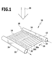
- a first exemplary embodiment of a solar radiation receiver according to the invention which is shown in FIG. 1 and denoted there by 10, comprises a fluid supply device 12. This is formed, for example, by a straight tube 14. This tube 14 serves as a manifold for distributing supplied heat transfer fluid (in particular air) to a plurality of absorber tubes 16.
- a fluid supply device 12 This is formed, for example, by a straight tube 14.
- This tube 14 serves as a manifold for distributing supplied heat transfer fluid (in particular air) to a plurality of absorber tubes 16.
- the fluid supply device 12 with its tube 14 extends in an extension direction 18.
- the absorber tubes 16 are oriented transversely and in particular perpendicular to this extension direction 18.
- the absorber tubes 16 are oriented parallel to one another, wherein adjacent absorber tubes 20a, 20b are spaced apart.
- the absorber tubes 16 have a smaller inner cross section than the tube 14 of the fluid supply device 12.
- the absorber tubes 16 are connected to the fluid supply device 12, so that heat transfer fluid divided into partial streams can be coupled via these into the absorber tubes 16.
- the absorber tubes 16 open into a fluid removal device 22, which comprises a collecting tube 24.
- This manifold 24 is spaced parallel to the tube 14.
- Via the fluid discharge device 22 can be collected and removed in the absorber tubes 16 heated heat transfer fluid; the heat transfer fluid is coupled via the fluid supply device 12 into the absorber tubes 16.
- the absorber tubes 16 In the flow in the absorber tubes 16 in a flow direction 26 (which is parallel to the extension direction of the absorber tubes 16), it is heated by solar radiation 28, and discharged via the fluid discharge device 22.
- the absorber tubes 16 may be, for example, drawn tubes without a weld. It is also possible that the tubes are made of sheet metal, for example, via a longitudinal weld.
- the absorber tubes have on their flow inside a structured surface to increase the degree of turbulence; increasing the degree of turbulence improves the heat transfer.
- the structuring can be produced for example by mechanical processing or coating.
- 16 multi-layer tubes are used for the absorber tubes, as shown in the EP 1 537 921 A1 are described.
- the absorber tubes 16 are arranged in one layer between the fluid supply device 12 and the fluid discharge device 22 and lie in particular in a plane; the center planes of the absorber tubes 16 lie on a common plane.
- the absorber tubes 16 have one or more compensation devices 30 for (length) expansion compensation.
- the temperature load of an absorber tube 16 leads to a longitudinal expansion. Different irradiation intensities can lead to different temperatures in different absorber tubes 16 and thus to different strains.
- the compensation device 30 on absorber tubes 16 such expansions can be compensated for in their effect on the solar radiation receiver 10.
- each absorber tube 16 has at least one compensation device 30.
- Each absorber tube 16 preferably has a compensation device 30 at or in the vicinity of an end facing the fluid supply device 12 and a corresponding compensation device at or in the vicinity of the opposite end (which faces the fluid removal device 22).
- a compensation device 30 is formed, for example, by providing regions 32 with different diameters (and therefore different cross-sections). Such a compensation device 30 thereby has a bellows-like shape.
- a compensation device 30 can be produced on an absorber tube 16 by mechanical processing (such as hydroforming) or welded, for example.
- a compensation device 30 it is also possible in principle for a compensation device 30 to extend over a large part of the length of an absorber tube 16 or over its entire length between the fluid supply device 12 and the fluid discharge device 22.
- an absorber tube 16 has a varying (inner) cross-section over its length. At areas with a smaller internal cross section, a higher flow velocity of the fluid and thus an increased heat transfer are obtained. By appropriate cross-sectional design, therefore, the heat transfer can be selectively increased at certain regions of an absorber tube 16. This can be done so that the total pressure loss is not too large.
- an absorber tube 16 may have an area with a widening course and in particular a conical course.
- the conical shape extends over the entire length of such absorber tube 16 between the fluid supply device 12 and the fluid removal device 22, wherein the large cross-section of the fluid supply means 12 and the small cross-section of the fluid discharge means 22. This allows the flow rate and thus increase the heat transfer in the flow direction 26. Furthermore, the temperature gradient between the fluid and a wall of the corresponding absorber tube 16 is reduced.
- a conical tube can be made from a trapezoidal sheet by welding. It is also possible, for example, to produce a conical tube from a seamless tube by forming.
- a fluid supply device 36 and a fluid discharge device 38 there is provided a fluid supply device 36 and a fluid discharge device 38.
- the fluid supply device 36 and the fluid discharge device 38 are formed on a tube 40 which extends in an extension direction 42.
- the tube 40 has, for example, a circular cross-section.
- a partition wall 44 is arranged, which separates the fluid supply means 36 and the fluid discharge means 38 from each other; the partition 44 forms a first chamber 46 and a second chamber 48, wherein the first chamber 46 serves as a distribution chamber for the fluid supply to absorber tubes 50 and the second chamber serves as a fluid collector for the discharge of fluid from the absorber tubes 50.
- an intermediate distribution tube 52 Arranged parallel to the tube 40 is an intermediate distribution tube 52 in which an intermediate distribution space 54 is formed. This is preferably arranged so that it is not exposed to solar radiation. As a result, the heat load of the intermediate distribution pipe 52 can be kept low.
- absorber tubes 56 run with an orientation perpendicular to the extension direction 42. These absorber tubes 56 open into the intermediate distribution space 54 at the intermediate distribution tube 52nd
- first layer absorber tubes 58 is provided.
- the absorber tubes 56 of the first layer 58 lie with respect to their center plane on a common plane. This plane is spaced from the partition wall 44.
- Heat transfer fluid is supplied from the first chamber 46 (and thus from the fluid supply device 36) to the intermediate distribution space 54 via the absorber tubes 56 of the first layer 58.
- absorber tubes 60 are provided, which lie in a second layer 62.
- the absorber tubes 60 of the second layer 62 lie with respect to their center plane on a common plane, which is spaced from the plane of the first layer 58 and spaced from the partition wall 44.
- the median plane of the partition lies between the plane of the first layer 58 and the plane of the second layer 62.
- Heat transfer fluid can be conducted via the absorber tubes 60 from the intermediate distribution space 54 into the second chamber 48 and thus to the fluid discharge device 38.
- the first layer 58 is located in front of the second layer 62.
- the absorber tubes 60 of the second layer 62 are arranged offset relative to the absorber tubes 56 of the first layer 58 in a direction parallel to the extension direction 42. This arrangement is preferably such that with respect to the solar radiation direction 64, the absorber tubes 60 of the second layer 62 are at least partially covered by absorber tubes 56 of the first layer 58.
- the intermediate distribution space 54 serves to bring together the partial mass flows of fluid which has been distributed to the absorber tubes 56 via the fluid supply device 36.
- fluid mixing can be performed.
- the mixture fluid is then distributed to the absorber tubes 60 of the second layer 62.
- different temperatures in the absorber tubes 56 can be at least partially compensated, or different tube temperatures do not have the same effect via the intermediate mixing in the intermediate distribution space 54.
- the heat transferring area can be increased. Furthermore, the absorber tubes 60, in which higher temperatures prevail, can be partially covered by the absorber tubes 56. This in turn allows the heat load to be reduced while at the same time increasing the efficiency of the solar radiation receiver 34.
- the absorber tubes 56, 60 may be provided with compensation devices 30, as described with reference to the first embodiment 10.
- absorber tubes 70 are arranged between a fluid supply device 66 and a fluid discharge device 68.
- About the injection can be the mass flow of the fluid in the absorber tubes 70 control or regulate.
- cooling can be achieved by blowing in a liquid or a gas. The cooling can be done by sensitive cooling and / or by evaporative cooling.
- air when air is passed through the absorber tubes 70 as heat transfer fluid, air is diverted at one or more locations (eg, ahead of a recuperator). It is also possible to inject another fluid, such as water or another gas.
- an injection takes place at an absorber tube 70 at one or more locations.
- the injection can be done on all or individual absorber tubes 70. It can take place in the direction of flow 76 or counter to the direction of flow.
- the injection nozzles 72 may be arranged on absorber tubes 16 of the radiation receiver 10 or absorber tubes 56, 60 of the radiation receiver 34.
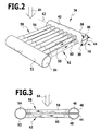
- a fluid supply device 80 and a fluid discharge device 82 are provided. These are in particular formed by corresponding tubes which are oriented parallel to one another.
- an intermediate distribution space 84 is arranged, which is formed for example by a tube 86 closed at both ends. This tube 86 is oriented in particular parallel to the fluid supply device 80 and fluid discharge device 82.
- Absorber tubes 88 are located between the fluid supply device 80 and the intermediate distribution space 84. They open into the intermediate distribution space 84. Furthermore, absorber tubes 90 are located between the intermediate distribution space 84 and the fluid discharge device 82; they open into the fluid discharge device 82.
- heat transfer fluid which is injected from different absorber tubes 88 into sub-streams, can mix.
- This mixture fluid is then divided again into partial flows, which are supplied via absorber tubes 90 of the fluid discharge device 82. Due to the intermediate mixing of fluid in the intermediate distribution space 84, temperature differences can be compensated, for example due to different irradiation of absorber tubes 88.
- the absorber tubes 90 fluid is supplied, which on a more uniform Temperature level is as if the fluid is fed directly from the fluid supply means 88 to the fluid discharge means 82.
- relatively high outlet temperatures can be achieved when the heat transfer fluid exits into the fluid discharge device 82; Due to the temperature compensation by the intermediate mixing, the irradiation power has to be adjusted so that the highest loaded absorber pipe does not get too hot; Intermediate mixing allows better distribution of the load via the fluid temperature compensation so that higher outlet temperatures can be achieved again.
- One or more intermediate distribution spaces 84 may be disposed on the solar radiation receivers 10, 34 or 65.
- an absorber tube structure 94 is arranged in a cavity 96.
- the absorber structure 94 may be formed as described above with reference to FIGS. 1 to 5.
- the cavity 96 is formed in a housing 98, which is thermally insulated from the exterior.
- the housing 98 has a passage opening 100 for solar radiation.
- the absorber structure 94 is arranged opposite this passage opening 100. For example, it is arranged on a wall 102 of the housing 98 or arranged facing away from this wall 102, which is opposite to a wall 104 (in particular parallel opposite), on which the passage opening 100 is formed. It is also possible to arrange further absorber tubes or absorber structures on other walls of the housing 98.
- the passage opening 100 is preferably closed by a glass element 106 (in particular quartz glass element or borosilicate glass element).
- a glass element 106 in particular quartz glass element or borosilicate glass element.
- the cavity 96 forms a cavity. Solar radiation enters the cavity 96 through the glass element 106.
- the envelope surface of the absorber structure 94 is preferably larger than the cross-sectional area of the passage opening 100. Then, the absorbing area is greater than the radiating area. As a result, the heat transfer in the absorber structure 94 can be lower. This in turn allows a lower pressure loss can be achieved.
- inner walls of the housing 68 which point into the cavity 96, are designed to be reflective. It can thereby be obtained in the cavity 96, a "homogenization" of radiation by reflection.
- the inner walls may be reflective with respect to solar radiation and / or infrared radiation.
- the inner walls can also be designed as a heat storage in order to provide a buffer effect.
- the cavity 96 may have a hollow cuboid shape.
- Other geometric configurations such as hollow sphere, hollow cylinder or hollow paraboloid are possible.
- a secondary concentrator for focusing the solar radiation is arranged on the passage opening 100 (not shown in the drawing).
- the passage opening 100 may be variable in shape and / or size (FIGS. 17 (a), (b), (c), (d)).
- an adjusting device 105 is arranged on the wall 104, in which the passage opening 100 is formed. By the adjustment 105, the area between the passage opening 100 and the wall 104 is covered, so that solar radiation can only pass through the passage opening 100 into the cavity 96.
- the shape and / or size of the passage opening 100 is adjustable on the adjusting device 105. The adjustability is realized, for example, by plastic deformability of the adjusting device 105.
- An absorber structure which comprises a plurality of absorber tubes, may be associated with a glass stem, for example made of quartz glass or borosilicate glass (FIGS. 7 to 9).
- a glass stem for example made of quartz glass or borosilicate glass (FIGS. 7 to 9).
- the glass stem is arranged in front of the absorber structure (with respect to the solar radiation direction).
- the glass of the glass stem allows the solar radiation to pass almost completely while at least partially absorbing infrared radiation coming from the absorber structure. This heat can (only) pass through heat conduction to the outside of the glass stem, being removed by radiation or convection.
- the thermal conductivity of glass is relatively low, the corresponding heat loss is low.
- the glass stem is provided with an anti-reflection coating to minimize reflection losses.
- a glass plate 112 of a plurality of absorber tubes 113 arranged in parallel is associated with a tube plate 110 as a glass stem.
- the solar radiation direction 114 is also marked.
- the glass plate 112 as a glass stem covers, in particular, all the absorber tubes 113 toward the solar radiation direction 114.
- each absorber tube 113 or a group of absorber tubes 113 is assigned its own glass plate.
- a glass plate may also be provided a plurality of juxtaposed flat glass strips, wherein the glass strips are separated from each other. These are indicated in Figure 7 by the reference numerals 115a, 115b, etc.
- Such a glass strip arrangement is cheaper to produce and more resistant to fracture than a one-piece design.
- absorber tubes 116 are arranged inside glass tubes 118.
- the glass tubes 118 completely surround the respective absorber tubes 116.
- glass tube parts 120 which are designed in particular in the form of glass half tubes, to surround the absorber tubes 116 only partially and / or arranged in front of them.
- the glass half pipes may be connected to each other or be separate from each other.
- a glass stem is formed by a plurality of parallel aligned glass half pipes, wherein adjacent glass half pipes are interconnected. The use of glass half pipes reduces the reflection of solar radiation and increases the mechanical stability.
- a glass stem as described above may also be arranged at the passage opening 100 instead of the glass element 106.
- the absorber tubes have a linear extension direction.
- absorber tubes have a non-linear extent through one or more bending areas. By bending different thermal expansion of absorber tubes can be compensated. Furthermore, it is possible to produce absorber structures with corresponding spatial shape by means of appropriate tube geometries.
- a plurality of such absorber tubes 122 can be positioned side by side to form an absorber structure 124.
- this makes it possible to achieve a "planar" absorber structure 124, which can be connected to a fluid supply device 126 and fluid discharge device 128, wherein the fluid supply device 126 and the fluid discharge device 128 can be formed, in particular, by linearly extending tubes lying parallel to one another.
- Figures 13 and 14 It is also possible ( Figures 13 and 14) to produce an absorber tube 130 which is bent two-dimensionally, and to assemble corresponding absorber tube 130 into a "three-dimensional" absorber structure 132.
- inlet openings 134 of the absorber tubes 130 are arranged on a circle and outlet openings 136 are arranged on a circle.
- fluid supply device 126 can then use a ring tube.
- a ring tube can be used as a fluid removal device.
- an absorber structure 140 is provided, which is not flat.
- the absorber structure 140 is designed, for example, dome-shaped. It has a curvature; Absorber tubes 142 of the absorber structure 140 are not arranged evenly.
- the geometry of the absorber structure 140 with the absorber tubes 142 can be adapted so that a uniform flux density distribution results with good expansion compensation.
- absorber tubes 144 (FIGS. 15, 16) to be bent three-dimensionally. As a result, thermal expansion can be compensated. A three-dimensional, curved absorber structure 145 can then be formed. This in turn can be used in the solar radiation receiver 138. By numerically controlled bending machines can be produced corresponding absorber tubes 142.
- the maximum possible outlet temperature can be substantially increased in the solar radiation receiver with absorber tubes (pipe receiver). It is expected that temperatures up to approx. 900 ° C can be achieved with high efficiencies and long service life of the solar radiation receiver. This makes it possible to combine a microturbine with a single solar radiation receiver into a solar small power station.
Landscapes
- Engineering & Computer Science (AREA)
- Physics & Mathematics (AREA)
- Life Sciences & Earth Sciences (AREA)
- Sustainable Development (AREA)
- Sustainable Energy (AREA)
- Thermal Sciences (AREA)
- Chemical & Material Sciences (AREA)
- Combustion & Propulsion (AREA)
- Mechanical Engineering (AREA)
- General Engineering & Computer Science (AREA)
- Heat-Pump Type And Storage Water Heaters (AREA)
- Photovoltaic Devices (AREA)
Applications Claiming Priority (1)
| Application Number | Priority Date | Filing Date | Title |
|---|---|---|---|
| DE102005035080A DE102005035080A1 (de) | 2005-07-21 | 2005-07-21 | Solarstrahlungsempfänger und Verfahren zur Steuerung und/oder Regelung der Massenstromverteilung und/oder zum Temperaturausgleich an einem Solarstrahlungsempfänger |
Publications (2)
| Publication Number | Publication Date |
|---|---|
| EP1746363A2 true EP1746363A2 (fr) | 2007-01-24 |
| EP1746363A3 EP1746363A3 (fr) | 2013-04-24 |
Family
ID=37074563
Family Applications (1)
| Application Number | Title | Priority Date | Filing Date |
|---|---|---|---|
| EP06117503.0A Withdrawn EP1746363A3 (fr) | 2005-07-21 | 2006-07-19 | Récepteur solaire et procédé de contrôle et/ou de régulation de la répartition du débit et/ou de la compensation de température dans un récepteur solaire |
Country Status (2)
| Country | Link |
|---|---|
| EP (1) | EP1746363A3 (fr) |
| DE (1) | DE102005035080A1 (fr) |
Cited By (9)
| Publication number | Priority date | Publication date | Assignee | Title |
|---|---|---|---|---|
| CN101788199A (zh) * | 2010-03-24 | 2010-07-28 | 益科博能源科技(上海)有限公司 | 太阳能接收器 |
| WO2010100992A1 (fr) | 2009-03-06 | 2010-09-10 | 三菱重工業株式会社 | Récepteur de chaleur solaire et système de génération d'énergie solaire thermique |
| US8360053B2 (en) | 2009-03-30 | 2013-01-29 | Mitsubishi Heavy Industries, Ltd. | Sunlight collecting heat receiver |
| US8378280B2 (en) | 2007-06-06 | 2013-02-19 | Areva Solar, Inc. | Integrated solar energy receiver-storage unit |
| EP2439462A4 (fr) * | 2009-06-05 | 2014-01-15 | Abengoa Solar New Tech Sa | Récepteur solaire à vapeur surchauffée |
| US8739512B2 (en) | 2007-06-06 | 2014-06-03 | Areva Solar, Inc. | Combined cycle power plant |
| US8807128B2 (en) | 2007-08-27 | 2014-08-19 | Areva Solar, Inc. | Linear fresnel solar arrays |
| US9022020B2 (en) | 2007-08-27 | 2015-05-05 | Areva Solar, Inc. | Linear Fresnel solar arrays and drives therefor |
| US10060418B2 (en) | 2011-11-25 | 2018-08-28 | Mitsubishi Heavy Industries, Ltd. | Solar heat receiver and solar heat power generation device |
Families Citing this family (5)
| Publication number | Priority date | Publication date | Assignee | Title |
|---|---|---|---|---|
| DE102009014491A1 (de) * | 2009-03-23 | 2010-09-30 | Rawema Countertrade Handelsgesellschaft Mbh | Kollektor |
| JP2011163593A (ja) * | 2010-02-05 | 2011-08-25 | Mitsubishi Heavy Ind Ltd | 太陽熱受熱器 |
| DE102011004265A1 (de) * | 2011-02-17 | 2012-08-23 | Siemens Aktiengesellschaft | Sonnenkollektorstrang für einen solarthermischen Durchlaufdampferzeuger |
| DE102016220522A1 (de) * | 2016-10-19 | 2018-04-19 | Deutsches Zentrum für Luft- und Raumfahrt e.V. | Receiver für Solarenergiegewinnungsanlagen sowie Solarenergiegewinnungsanlage |
| DE102022108479A1 (de) | 2022-04-07 | 2023-10-12 | Deutsches Zentrum für Luft- und Raumfahrt e.V. | Receiver sowie Solargewinnungsanlage mit einem Receiver |
Citations (1)
| Publication number | Priority date | Publication date | Assignee | Title |
|---|---|---|---|---|
| EP1537921A1 (fr) | 2003-12-05 | 2005-06-08 | Deutsches Zentrum für Luft- und Raumfahrt e.V. | Méthode de fabrication d'un tube multicouche pour le guidage des fluides de transfer de chaleur et tube multicouche |
Family Cites Families (25)
| Publication number | Priority date | Publication date | Assignee | Title |
|---|---|---|---|---|
| FR1179202A (fr) * | 1949-03-24 | 1959-05-21 | Centre Nat Rech Scient | Dispositif pour la transformation de l'énergie solaire en énergie mécanique |
| FR2378241A1 (fr) * | 1977-01-21 | 1978-08-18 | Teculescu Mihnea | Capteur d'energie solaire |
| US4291677A (en) * | 1977-12-27 | 1981-09-29 | Monk Robert J | Solar energy collector |
| FR2431101A1 (fr) * | 1978-06-30 | 1980-02-08 | Fives Cail Babcock | Chaudiere solaire |
| US4245618A (en) * | 1978-10-10 | 1981-01-20 | The Babcock & Wilcox Co. | Vapor generator |
| JPS55143356A (en) * | 1979-04-25 | 1980-11-08 | Sanyo Electric Co Ltd | Solar heat collector |
| US4280482A (en) * | 1979-07-16 | 1981-07-28 | Seige Corporation | Method and apparatus for collecting, intensifying and storing solar energy |
| JPS5661539A (en) * | 1979-10-22 | 1981-05-27 | Yoshikane Ito | Boiler utilizing solar heat |
| DE3010523C2 (de) * | 1980-03-19 | 1985-09-12 | Vereinigte Aluminium-Werke AG, 1000 Berlin und 5300 Bonn | Wärmetauscher für Hausdächer, Fassaden, Zäune o.dgl. |
| DE8019308U1 (de) * | 1980-07-18 | 1980-10-23 | Schaarschmidt, Lothar, 7100 Heilbronn | Waermeabsorber |
| FR2490331A1 (fr) * | 1980-09-16 | 1982-03-19 | Electricite De France | Installation de production d'energie mettant en oeuvre un fluide auxiliaire, notamment utilisant le rayonnement solaire |
| JPS6011064A (ja) * | 1983-06-29 | 1985-01-21 | Matsushita Electric Works Ltd | 強制循環式太陽熱温水器 |
| US4602614A (en) * | 1983-11-30 | 1986-07-29 | United Stirling, Inc. | Hybrid solar/combustion powered receiver |
| DE29507492U1 (de) * | 1995-05-05 | 1996-03-21 | Krüss, Hartmut, 19243 Wittenburg | Warmluftgenerator - Einrichtung zur Speicherung von Wärme, die mit Sonnenenergie erzeugt wird |
| JPH08327159A (ja) * | 1995-06-01 | 1996-12-13 | Shiroki Corp | 蒸気発生器 |
| DE19608138C1 (de) * | 1996-03-02 | 1997-06-19 | Deutsche Forsch Luft Raumfahrt | Rinnenkollektor |
| GB9613004D0 (en) * | 1996-06-20 | 1996-08-21 | Mahdjuri F | Evacuated heat pipe solar collector with limited maximum operating temperature using bimetal material |
| DE19736335C1 (de) * | 1997-08-21 | 1999-03-18 | Deutsch Zentr Luft & Raumfahrt | Blende zur Regulierung der Fluidströmung in einem Absorberrohr eines solarthermischen Kraftwerks |
| DE20121707U1 (de) * | 2000-06-19 | 2003-05-15 | Müller, Friedrich Udo, 74074 Heilbronn | Vorrichtung zum Erwärmen und Kühlen eines flüssigen Mediums, insbesondere Sonnenkollektor |
| BE1013693A3 (nl) * | 2000-09-19 | 2002-06-04 | Suria Holdings Sarl | Werkwijze en inrichting voor het vervaardigen van stoom met zonne-energie. |
| DE20102503U1 (de) * | 2001-02-13 | 2001-05-31 | Thomas Lorenz Industrietechnik, 99897 Tambach-Dietharz | Gehäuse für einen Sonnenkollektor |
| DE10152971C1 (de) * | 2001-10-19 | 2002-12-05 | Deutsch Zentr Luft & Raumfahrt | Solarthermisches Kraftwerk und Regelungsverfahren für ein solarthermisches Kraftwerk |
| DE20209222U1 (de) * | 2002-06-13 | 2002-11-07 | Wolf GmbH, 84048 Mainburg | Solarabsorber mit einem Gehäuse und aus dem Gehäuse herausragenden Sammelrohr |
| DE10248068B4 (de) * | 2002-10-11 | 2007-09-27 | Deutsches Zentrum für Luft- und Raumfahrt e.V. | Anlage zur solarthermischen Dampferzeugung und Verfahren zur solarthermischen Erzeugung von Dampf |
| US6931851B2 (en) * | 2002-12-13 | 2005-08-23 | The Boeing Company | Solar central receiver with inboard headers |
-
2005
- 2005-07-21 DE DE102005035080A patent/DE102005035080A1/de not_active Ceased
-
2006
- 2006-07-19 EP EP06117503.0A patent/EP1746363A3/fr not_active Withdrawn
Patent Citations (1)
| Publication number | Priority date | Publication date | Assignee | Title |
|---|---|---|---|---|
| EP1537921A1 (fr) | 2003-12-05 | 2005-06-08 | Deutsches Zentrum für Luft- und Raumfahrt e.V. | Méthode de fabrication d'un tube multicouche pour le guidage des fluides de transfer de chaleur et tube multicouche |
Cited By (9)
| Publication number | Priority date | Publication date | Assignee | Title |
|---|---|---|---|---|
| US8378280B2 (en) | 2007-06-06 | 2013-02-19 | Areva Solar, Inc. | Integrated solar energy receiver-storage unit |
| US8739512B2 (en) | 2007-06-06 | 2014-06-03 | Areva Solar, Inc. | Combined cycle power plant |
| US8807128B2 (en) | 2007-08-27 | 2014-08-19 | Areva Solar, Inc. | Linear fresnel solar arrays |
| US9022020B2 (en) | 2007-08-27 | 2015-05-05 | Areva Solar, Inc. | Linear Fresnel solar arrays and drives therefor |
| WO2010100992A1 (fr) | 2009-03-06 | 2010-09-10 | 三菱重工業株式会社 | Récepteur de chaleur solaire et système de génération d'énergie solaire thermique |
| US8360053B2 (en) | 2009-03-30 | 2013-01-29 | Mitsubishi Heavy Industries, Ltd. | Sunlight collecting heat receiver |
| EP2439462A4 (fr) * | 2009-06-05 | 2014-01-15 | Abengoa Solar New Tech Sa | Récepteur solaire à vapeur surchauffée |
| CN101788199A (zh) * | 2010-03-24 | 2010-07-28 | 益科博能源科技(上海)有限公司 | 太阳能接收器 |
| US10060418B2 (en) | 2011-11-25 | 2018-08-28 | Mitsubishi Heavy Industries, Ltd. | Solar heat receiver and solar heat power generation device |
Also Published As
| Publication number | Publication date |
|---|---|
| EP1746363A3 (fr) | 2013-04-24 |
| DE102005035080A1 (de) | 2007-01-25 |
Similar Documents
| Publication | Publication Date | Title |
|---|---|---|
| EP1746363A2 (fr) | Récepteur solaire et procédé de contrôle et/ou de régulation de la répartition du débit et/ou de la compensation de température dans un récepteur solaire | |
| EP3102899B1 (fr) | Appareil à écoulement permettant de guider un courant de fluide | |
| DE2008311C3 (de) | Wärmetauscher | |
| DE3710244C2 (fr) | ||
| WO1990010835A1 (fr) | Absorbeur pour un systeme d'absorption diffusion | |
| DE10239700B3 (de) | Solarempfänger für ein solarthermisches Kraftwerk | |
| DE2632238A1 (de) | Selbstregulierender kraftstoffverdampfer fuer brennkraftmaschinen mit funkenzuendung | |
| DE10113637C1 (de) | Solarempfänger | |
| DE102010046831B4 (de) | Receiver für Solarenergiegewinnungsanlagen | |
| DE2602211C2 (de) | Rohrartiger Wärmetauscher | |
| DE19707184B4 (de) | Warmwasserspeicher | |
| EP3210890B1 (fr) | Refroidissement de carburant pour un moteur | |
| DE102006021972B4 (de) | Solarthermisches Kraftwerk und Verfahren zur Umwandlung von thermischer Energie in elektrische/mechanische Energie | |
| DE2321872A1 (de) | Heissgaskolbenmaschine | |
| DE19802670C2 (de) | Wärmeübertrager | |
| DE102013221889B4 (de) | Receiver für Solarenergiegewinnungsanlagen | |
| DE3812238A1 (de) | Vorrichtung zum umsetzen von sonnenenergie in prozesswaerme | |
| EP3538823B1 (fr) | Récepteur doté de modules absorbeurs | |
| DE3117515A1 (de) | "ueberstroemgehaeuse fuer eine gasturbinenanlage" | |
| EP4015935B1 (fr) | Collecteur solaire | |
| DE3225299A1 (de) | Waermetauscher, insbesondere fuer das cargomedium eines fluessiggastankers | |
| DE10311532B4 (de) | Wärmeverteilermodul | |
| DE102016103229B4 (de) | Einspritzung in Rohre eines Rohrbündelwärmetauschers | |
| EP2350548A1 (fr) | Dispositif de transfert de chaleur et de purification d'air et procédé pour transférer de la chaleur | |
| CH706691A2 (de) | Absorberanordnung für einen Rinnenkollektor. |
Legal Events
| Date | Code | Title | Description |
|---|---|---|---|
| PUAI | Public reference made under article 153(3) epc to a published international application that has entered the european phase |
Free format text: ORIGINAL CODE: 0009012 |
|
| AK | Designated contracting states |
Kind code of ref document: A2 Designated state(s): AT BE BG CH CY CZ DE DK EE ES FI FR GB GR HU IE IS IT LI LT LU LV MC NL PL PT RO SE SI SK TR |
|
| AX | Request for extension of the european patent |
Extension state: AL BA HR MK YU |
|
| RIC1 | Information provided on ipc code assigned before grant |
Ipc: F24J 2/07 20060101AFI20121214BHEP |
|
| PUAL | Search report despatched |
Free format text: ORIGINAL CODE: 0009013 |
|
| AK | Designated contracting states |
Kind code of ref document: A3 Designated state(s): AT BE BG CH CY CZ DE DK EE ES FI FR GB GR HU IE IS IT LI LT LU LV MC NL PL PT RO SE SI SK TR |
|
| AX | Request for extension of the european patent |
Extension state: AL BA HR MK RS |
|
| RIC1 | Information provided on ipc code assigned before grant |
Ipc: F24J 2/07 20060101AFI20130315BHEP |
|
| 17P | Request for examination filed |
Effective date: 20131023 |
|
| RBV | Designated contracting states (corrected) |
Designated state(s): AT BE BG CH CY CZ DE DK EE ES FI FR GB GR HU IE IS IT LI LT LU LV MC NL PL PT RO SE SI SK TR |
|
| AKX | Designation fees paid |
Designated state(s): AT BE BG CH CY CZ DE DK EE ES FI FR GB GR HU IE IS IT LI LT LU LV MC NL PL PT RO SE SI SK TR |
|
| 17Q | First examination report despatched |
Effective date: 20170203 |
|
| STAA | Information on the status of an ep patent application or granted ep patent |
Free format text: STATUS: THE APPLICATION IS DEEMED TO BE WITHDRAWN |
|
| 18D | Application deemed to be withdrawn |
Effective date: 20170614 |