EP3538823B1 - Récepteur doté de modules absorbeurs - Google Patents
Récepteur doté de modules absorbeurs Download PDFInfo
- Publication number
- EP3538823B1 EP3538823B1 EP17798127.1A EP17798127A EP3538823B1 EP 3538823 B1 EP3538823 B1 EP 3538823B1 EP 17798127 A EP17798127 A EP 17798127A EP 3538823 B1 EP3538823 B1 EP 3538823B1
- Authority
- EP
- European Patent Office
- Prior art keywords
- receiver
- annular gap
- retaining
- orifice plate
- absorber
- Prior art date
- Legal status (The legal status is an assumption and is not a legal conclusion. Google has not performed a legal analysis and makes no representation as to the accuracy of the status listed.)
- Active
Links
Images


Classifications
-
- F—MECHANICAL ENGINEERING; LIGHTING; HEATING; WEAPONS; BLASTING
- F24—HEATING; RANGES; VENTILATING
- F24S—SOLAR HEAT COLLECTORS; SOLAR HEAT SYSTEMS
- F24S40/00—Safety or protection arrangements of solar heat collectors; Preventing malfunction of solar heat collectors
- F24S40/50—Preventing overheating or overpressure
- F24S40/55—Arrangements for cooling, e.g. by using external heat dissipating means or internal cooling circuits
-
- F—MECHANICAL ENGINEERING; LIGHTING; HEATING; WEAPONS; BLASTING
- F24—HEATING; RANGES; VENTILATING
- F24S—SOLAR HEAT COLLECTORS; SOLAR HEAT SYSTEMS
- F24S10/00—Solar heat collectors using working fluids
- F24S10/80—Solar heat collectors using working fluids comprising porous material or permeable masses directly contacting the working fluids
-
- F—MECHANICAL ENGINEERING; LIGHTING; HEATING; WEAPONS; BLASTING
- F24—HEATING; RANGES; VENTILATING
- F24S—SOLAR HEAT COLLECTORS; SOLAR HEAT SYSTEMS
- F24S20/00—Solar heat collectors specially adapted for particular uses or environments
- F24S20/20—Solar heat collectors for receiving concentrated solar energy, e.g. receivers for solar power plants
-
- F—MECHANICAL ENGINEERING; LIGHTING; HEATING; WEAPONS; BLASTING
- F24—HEATING; RANGES; VENTILATING
- F24S—SOLAR HEAT COLLECTORS; SOLAR HEAT SYSTEMS
- F24S25/00—Arrangement of stationary mountings or supports for solar heat collector modules
- F24S25/60—Fixation means, e.g. fasteners, specially adapted for supporting solar heat collector modules
- F24S2025/6004—Fixation means, e.g. fasteners, specially adapted for supporting solar heat collector modules by clipping, e.g. by using snap connectors
-
- F—MECHANICAL ENGINEERING; LIGHTING; HEATING; WEAPONS; BLASTING
- F24—HEATING; RANGES; VENTILATING
- F24S—SOLAR HEAT COLLECTORS; SOLAR HEAT SYSTEMS
- F24S25/00—Arrangement of stationary mountings or supports for solar heat collector modules
- F24S25/60—Fixation means, e.g. fasteners, specially adapted for supporting solar heat collector modules
-
- Y—GENERAL TAGGING OF NEW TECHNOLOGICAL DEVELOPMENTS; GENERAL TAGGING OF CROSS-SECTIONAL TECHNOLOGIES SPANNING OVER SEVERAL SECTIONS OF THE IPC; TECHNICAL SUBJECTS COVERED BY FORMER USPC CROSS-REFERENCE ART COLLECTIONS [XRACs] AND DIGESTS
- Y02—TECHNOLOGIES OR APPLICATIONS FOR MITIGATION OR ADAPTATION AGAINST CLIMATE CHANGE
- Y02E—REDUCTION OF GREENHOUSE GAS [GHG] EMISSIONS, RELATED TO ENERGY GENERATION, TRANSMISSION OR DISTRIBUTION
- Y02E10/00—Energy generation through renewable energy sources
- Y02E10/40—Solar thermal energy, e.g. solar towers
- Y02E10/44—Heat exchange systems
Definitions
- the present invention relates to a receiver for solar energy generation systems according to the preamble of claim 1.
- the absorber modules each contain a porous absorber body that faces the incident solar radiation. Air is sucked in through the absorber body and warms up as it flows through the absorber body.
- the receiver is suitable for large energy generation systems in which, for example, numerous heliostats are distributed over a field and reflect solar radiation onto the receiver. This creates a high concentration of radiation on the receiver, which results in temperatures in the range of up to 1100 ° C on the absorber module.
- a supporting structure is provided which carries numerous absorber modules. Each absorber module consists of an absorber head and an absorber body held by the absorber head. A hot air duct connects to the absorber body. The generated hot air is used, for example, for the operation of work machines such as Turbines used for power generators and cools down, but still contains residual heat or has a usable temperature difference compared to the ambient temperature.
- the air is returned to the solar receiver and part of the air is guided along the walls of the hot air ducts in order to cool them.
- the return air flows between the absorber modules in order to exit at the front towards the front. It is then sucked back into the absorber body together with the ambient air.
- the solar radiation concentrated on the receiver is normally not distributed homogeneously. Rather, the radiation flux density has approximately the form of a Gaussian distribution.
- Each absorber module is assigned a diaphragm which throttles the hot air mass flow and by means of which the hot air mass flow is adapted to the radiation flux density.
- the air mass flow ratio of the air mass flow of the process air flowing through the absorber module is set at each absorber module relative to the air mass flows through the other absorber modules, whereby an optimized mass flow distribution of the hot air flows flowing out of the absorber modules is achieved.
- the return air flows around the absorber modules and is therefore cooled.
- the temperature of the absorber modules therefore also depends on the temperature and the mass flow of the return air. For this reason, the mass flow of the return air is set individually for each module and thus the mass flow and temperature distribution of the absorber modules is further optimized.
- the return air flowing along the absorber not only influences the temperature of the absorber modules, but also determines the temperature distribution of the supporting structure.
- An individual setting of this mass flow ensures that areas of this structure that are subject to high thermal loads are adequately cooled, thus preventing thermal overloading and, for example, unnecessary cooling or the use of high-temperature-resistant materials.
- a receiver module of a solar energy generation system known with a support structure which comprises a cavity and supports several absorber modules.
- the absorber modules each include a hot air pipe which is surrounded by a cooling jacket within the cavity in such a way that an annular space is formed between the hot air pipe and the cooling jacket, through which return air flows to the front of the receiver.
- the invention is based on the object of creating a receiver of the type mentioned in the introduction with a structurally simple to implement possibility of setting the return mass flow.
- the receiver according to the invention for solar energy generation systems has a support structure that carries absorber modules.
- the absorber modules each contain a front absorber body to which a hot air duct is connected.
- Process air flows through the individual absorbers, which is fed to a consumer as a heat transfer medium. After the consumer, the cooled process air is at least partially fed back to the receiver as so-called return air via an air return system.
- this return air is distributed to the individual absorbers without mixing with the hot air. It flows in return air channels along the holding tube and the absorber in front of the absorber body.
- the invention is characterized in that in the return air ducts of individual or all absorber modules there is in each case at least one diaphragm which throttles the return air mass flow and which determines the mass flow of the return air of the relevant absorber, the return air diaphragm being fastened via a detachable connection in the annular gap and at least one retaining ring includes, which is fixed to the relevant guide tube and / or the relevant holding tube.
- the ratio of the mass flows in the annular gaps can be adjusted.
- the ratio of the mass flows of the return air of the absorber modules to one another can be set via the return air screens and the cooling of those modules and the receiver structure can be adapted to the distribution of the radiated power.
- the internal heat loss between the hot and return air is significantly reduced while at the same time ensuring the minimum cooling of the absorber and supporting structure.
- the return mass flow is adapted to the respective hot air mass flow of the absorber and an optimal return of the air is achieved. This ensures maximum efficiency of the solar energy generation system.
- the screens are designed based on the mainly existing radiation flux density distribution and the temperature distribution of the supporting structure in the main load case, and a significantly improved distribution is achieved for most of the operating time.
- the design of the diaphragms as simple sheet metal parts is designed in such a way that the flow area of the return air is reduced from hardly to very much, resulting in a large adjustment range.
- Another essential feature of the diaphragms described is the simple assembly and interchangeability, since the annular gap between the hot air pipe and the guide pipe is easily accessible from the outside on one side and the diaphragms are attached in this gap via an easily detachable connection.
- the good accessibility makes it possible to assemble these throttle components only after the receiver has been installed in a tower of the solar production system, and thus to significantly reduce the error-proneness of assembly, since the effort involved in reliably assigning the panels is significantly lower.
- the diaphragm according to the invention can be designed as a perforated ring which is largely positioned within the annular gap between the hot air tube and the guide tube.
- it can also be designed so that a large part of the diaphragm is located outside the guide tube in the form of a retaining ring and the return mass flow is only regulated by small interference surfaces that are positioned within the annular gap and are formed by diaphragm elements.
- these two embodiment variants described can also be designed asymmetrically.
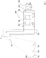
- a solar energy generation system 100 is shown schematically simplified. Sunlight is on the heliostat 110 of a heliostat field 120 on the Receiver 1 according to the invention reflected.
- the receiver 1 is designed as an open volumetric receiver, with air being sucked in from the area in front of the front side 1a of the receiver and forming the process air.
- the process air is heated by the receiver 1 and fed to a consumer via hot air lines 130.
- the consumer can be, for example, a steam generator 140 with a conventional water steam circuit 150 or a heat store 160.
- the heated process air can also be used as process heat, for example to produce hydrogen.
- the cooled process air is fed to the receiver 1 via an air return system 170. There it is used completely or only partially to cool the receiver and finally passed in front of the front side 1a and there, for the most part, is sucked in again as process air.
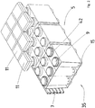
- a receiver module 5 is shown schematically simplified. Such receiver modules are both an essential part of a support structure of the receiver 1 according to the invention and a main component of the air duct inside the receiver.
- the receiver module 5 has several holes 9 on a front side, into which absorber modules 11 are inserted.
- outlets 15 for the hot air are in connection with the absorber modules 11.
- the return air 35 is fed to the side of the receiver module 5 and is blown out evenly distributed between the absorber modules 11 in front of the front of the receiver module 5.
- a receiver module of the receiver according to the invention including three absorber modules 11 is shown in section.
- an absorber module 11 consists of a cup-shaped absorber body 13 which holds an absorber head 17.
- the absorber body 13 opens into a hot air duct, the mass flows of each individual absorber module 11 being set in relation to other absorber mass flows of the receiver 1 by means of differently designed hot air baffles 39.
- the absorber body 13 is inserted into a holding tube 21 and connected to a support structure 7 via this.
- the holding tube 21 is thermally insulated from the hot air duct via insulation 37.
- the support structure 7 and the guide tubes 41 are cooled.
- some of the return air flows through flow channels 45 in the guide tubes 41 into an annular gap between the respective holding tube 21 and the respective guide tube 41.
- a return air screen 43 At the end of this annular gap there is a return air screen 43, which respective annular gap 50 throttles the amount of air flowing.
- the air After passing through the return air diaphragms 43, the air reaches an intermediate space 40 between the absorbers and from there flows on through gaps between the absorber bodies 13 in front of the front side 1a.
- the pressure loss of the return orifice 43 is significantly greater than that of the flow channels 45 in the guide tubes. Accordingly, the mass flow of the return air, which flows through the gap between the holding tube 21 and the guide tube 41 and cools the holding tubes 21 and the absorber body 13, is determined by the return air apertures 43 or by their free flow surface 42.
- FIG Fig. 6 This variant of a return air diaphragm 43 is shown in FIG Fig. 6 shown.
- the asymmetrical design is necessary if the diaphragm 43 not only has a purely throttling function, but also the profile of the flow between the holding tube 21 and the guide tube 41 is to be adjusted. This is necessary when the air is not fed into the annular gap 50 via the flow channels uniformly, but is, for example, much more pronounced from one direction. In this case the flow must come from this direction be throttled considerably more in order to achieve a uniform flow through the annular gap 50.
- the warm air does not flow out evenly.
- Such a desired asymmetrical flow can also be achieved via the in Fig. 6 shown aperture.
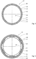
- the return air diaphragm 43 according to Figure 4 comprises a retaining ring 44 which is arranged in the annular gap 50 between the guide tube 41 and the support tube 21 and which is provided with six retaining webs 47 which each engage in a fixing slot 48 which is formed on the guide tube 41. As a result, the return air screen 43 is securely held on the guide tube 41.
- the return air screen 43 shown also comprises an inner ring 45, which is also arranged in the annular gap between the guide tube 41 and the holding tube 21 and which rests with its inner annular surface on the holding tube 21.
- the inner ring 45 is connected to the retaining ring 44 via connecting webs 46, which extend in the radial direction with respect to the axis of the retaining tube 21.
- the free flow surface 42 of the return air screen 43 is fixed by the retaining ring 44, the inner ring 45 and the connecting webs 46 or arcuate windows are defined which define the free flow surface 42.
- the retaining ring 44, the inner ring 45 and the connecting webs can be designed as a function of the desired free flow surface 42 with regard to their dimensions.
- the illustrated embodiment of a return air screen 43 comprises a retaining ring 44 which rests on the outer circumferential surface of the guide tube 41 and from which retaining webs 47 branch off in the radial direction inward, the retaining slots 48 of the guide tube 41 pass through.
- the six holding webs 47 in the present case each merge in the annular gap between the holding tube 21 and the guide tube 41 into a diaphragm element 55, which partially fills the annular gap 50 and has an arched plan Has.
- the screen elements 55 each have a support web 51, which is supported in the radial direction on the peripheral surface of the holding tube 21.
- the diaphragm elements 55 only partially cover the annular gap 50, so that a free flow surface 42 remains for the return air between adjacent diaphragm elements 55 and between the individual diaphragm elements 55 and the holding tube 21.
- the diaphragm elements 55 can have different dimensions.
- FIG. 6 An embodiment of a return air screen 43 is shown, which comprises an outer retaining ring 44, which rests on the outer circumferential surface of the guide tube 41 and from which retaining webs 47 protrude in the radial direction inward, the retaining slots 48 of the guide tube 41 extend through.
- Two of the holding webs 47 merge within the annular gap 50 between the guide tube 41 and the holding tube 21 into panel elements 55, which follow the panel elements Figure 5 correspond.
- the four other holding webs 47 merge into a partial diaphragm ring 52 which extends over an angular range of approximately 170 ° and is also supported on its inside in the radial direction via support webs 51 on the outside of the holding tube 21.
- the diaphragm part ring 52 is provided with slots 53 and / or bores 54.
- the dimensions of the diaphragm elements 55 and the diaphragm partial ring 52 define the free flow surface 42 which can be made available by the return air diaphragm 43.
Landscapes
- Engineering & Computer Science (AREA)
- Chemical & Material Sciences (AREA)
- Mechanical Engineering (AREA)
- General Engineering & Computer Science (AREA)
- Sustainable Energy (AREA)
- Thermal Sciences (AREA)
- Life Sciences & Earth Sciences (AREA)
- Combustion & Propulsion (AREA)
- Physics & Mathematics (AREA)
- Sustainable Development (AREA)
- Dispersion Chemistry (AREA)
- Engine Equipment That Uses Special Cycles (AREA)
- Air-Flow Control Members (AREA)
- Cooling Or The Like Of Electrical Apparatus (AREA)
- Duct Arrangements (AREA)
- Buildings Adapted To Withstand Abnormal External Influences (AREA)
Claims (10)
- Récepteur pour une centrale solaire (100), le récepteur comprenant une structure de support (7) portant une pluralité de modules absorbeurs (11) sur une face avant du récepteur, chaque module absorbeur (11) comprenant un tube de fixation (21) qui vient en prise avec un tube de guidage (41) de la structure de support (7) de manière qu'un interstice annulaire (50) est formé entre le tube de fixation (21) et le tube de guidage (41), de l'air de recirculation circulant jusqu'à la face avant du récepteur à travers ledit interstice annulaire (50) pour refroidir la structure de support (7) et/ou le respectif module absorbeur (11) pendant le fonctionnement, caractérisé en ce qu'au moins une plaque à orifice (43) étranglante pour l'air de recirculation est disposée dans au moins un des interstices annulaires (50), ladite plaque à orifice (43) pour l'air de recirculation définissant un débit massique de l'air de recirculation, qui circule jusqu'à la face avant du récepteur à travers le respectif interstice annulaire (50), et la plaque à orifice (43) pour l'air de recirculation étant montée dans l'interstice annulaire (50) via une liaison amovible et ayant au moins une bague de fixation (44) qui est fixée au respectif tube de guidage (41) et/ou au respectif tube de fixation (21).
- Récepteur selon la revendication 1, caractérisé en ce que la bague de fixation (44) est disposée à l'intérieur de l'interstice annulaire (50).
- Récepteur selon la revendication 1 ou 2, caractérisé en ce que la bague de fixation (44) entoure le tube de guidage (41).
- Récepteur selon l'une quelconque des revendications 1 à 3, caractérisé en ce que la plaque à orifice (43) pour l'air de recirculation a une bague intérieure (45) qui est disposée à l'intérieur de l'interstice annulaire (50) entre le tube de fixation (21) et le tube de guidage (41) et est reliée à la bague de fixation (44) via au moins une traverse de liaison (46).
- Récepteur selon l'une quelconque des revendications 1 à 4, caractérisé en ce qu'au moins une traverse de fixation (47), qui vient en prise avec une fente de fixation (48) du tube de guidage (41), fait saillie de la bague de fixation (44) dans la direction radiale.
- Récepteur selon l'une quelconque des revendications 1 à 5, caractérisé en ce que la plaque à orifice (43) pour l'air de recirculation comprend au moins un élément de plaque à orifice (55) qui remplit partiellement l'interstice annulaire (50).
- Récepteur selon la revendication 6, caractérisé en ce que l'élément de plaque à orifice (55) a un plan en forme d'arc.
- Récepteur selon la revendication 6 ou 7 en combinaison avec l'une quelconque des revendications 2 à 6, caractérisé en ce que l'élément de plaque à orifice (55) est relié à la bague de fixation (44) via la traverse de fixation (47).
- Récepteur selon l'une quelconque des revendications 6 à 8, caractérisé en ce que l'élément de plaque à orifice (55) a au moins une traverse de support (51) qui s'appuie au tube de fixation (21) dans la direction radiale.
- Récepteur selon l'une quelconque des revendications 1 à 9, caractérisé en ce qu'au moins deux plaques à orifice (43) pour l'air de recirculation, qui sont de préférence de construction identique et qui sont tournées l'une par rapport à l'autre dans la direction circonférentielle, sont disposées dans l'interstice annulaire (50).
Applications Claiming Priority (2)
| Application Number | Priority Date | Filing Date | Title |
|---|---|---|---|
| DE102016121654.2A DE102016121654B3 (de) | 2016-11-11 | 2016-11-11 | Receiver mit Absorbermodulen |
| PCT/EP2017/077509 WO2018086910A1 (fr) | 2016-11-11 | 2017-10-26 | Récepteur doté de modules absorbeurs |
Publications (2)
| Publication Number | Publication Date |
|---|---|
| EP3538823A1 EP3538823A1 (fr) | 2019-09-18 |
| EP3538823B1 true EP3538823B1 (fr) | 2020-12-02 |
Family
ID=60269376
Family Applications (1)
| Application Number | Title | Priority Date | Filing Date |
|---|---|---|---|
| EP17798127.1A Active EP3538823B1 (fr) | 2016-11-11 | 2017-10-26 | Récepteur doté de modules absorbeurs |
Country Status (8)
| Country | Link |
|---|---|
| EP (1) | EP3538823B1 (fr) |
| CN (1) | CN208139605U (fr) |
| AU (1) | AU2017356608A1 (fr) |
| CY (1) | CY1123923T1 (fr) |
| DE (1) | DE102016121654B3 (fr) |
| ES (1) | ES2859491T3 (fr) |
| PT (1) | PT3538823T (fr) |
| WO (1) | WO2018086910A1 (fr) |
Families Citing this family (1)
| Publication number | Priority date | Publication date | Assignee | Title |
|---|---|---|---|---|
| CA3199975A1 (fr) * | 2020-11-25 | 2022-06-02 | Edward H. Sargent | Conversion amelioree de co2 fixe par chimisorption dans des systemes electrochimiques a base d'amine |
Family Cites Families (8)
| Publication number | Priority date | Publication date | Assignee | Title |
|---|---|---|---|---|
| DE19744541C2 (de) * | 1997-10-09 | 2001-05-03 | Deutsch Zentr Luft & Raumfahrt | Solarempfänger |
| DE10113637C1 (de) * | 2001-03-21 | 2002-11-07 | Deutsch Zentr Luft & Raumfahrt | Solarempfänger |
| DE102009006952A1 (de) * | 2009-01-30 | 2010-08-05 | Saint-Gobain Industriekeramik Rödental GmbH | Gehäuse für ein Solarabsorbermodul, Solarabsorbermodul und Solarabsorberanordnung sowie Verfahren zur Herstellung |
| DE102010037206A1 (de) * | 2010-08-27 | 2012-03-01 | Solarhybrid Ag | Wärmetauscher |
| DE102010046831B4 (de) * | 2010-09-29 | 2015-04-09 | Deutsches Zentrum für Luft- und Raumfahrt e.V. | Receiver für Solarenergiegewinnungsanlagen |
| ITFI20110076A1 (it) * | 2011-04-19 | 2012-10-20 | Unitech Textile Machinery S P A | "macchina per il trattamento di tessuti con recupero di calore" |
| DE102013221887B3 (de) * | 2013-10-28 | 2015-03-19 | Deutsches Zentrum für Luft- und Raumfahrt e.V. | Receiver für Solarenergiegewinnungsanlagen |
| DE102013221889B4 (de) * | 2013-10-28 | 2019-08-01 | Kraftanlagen München Gmbh | Receiver für Solarenergiegewinnungsanlagen |
-
2016
- 2016-11-11 DE DE102016121654.2A patent/DE102016121654B3/de active Active
-
2017
- 2017-10-26 WO PCT/EP2017/077509 patent/WO2018086910A1/fr not_active Ceased
- 2017-10-26 EP EP17798127.1A patent/EP3538823B1/fr active Active
- 2017-10-26 AU AU2017356608A patent/AU2017356608A1/en not_active Abandoned
- 2017-10-26 ES ES17798127T patent/ES2859491T3/es active Active
- 2017-10-26 PT PT177981271T patent/PT3538823T/pt unknown
- 2017-11-10 CN CN201721503155.2U patent/CN208139605U/zh active Active
-
2021
- 2021-02-18 CY CY20211100135T patent/CY1123923T1/el unknown
Non-Patent Citations (1)
| Title |
|---|
| None * |
Also Published As
| Publication number | Publication date |
|---|---|
| EP3538823A1 (fr) | 2019-09-18 |
| WO2018086910A1 (fr) | 2018-05-17 |
| AU2017356608A1 (en) | 2019-05-30 |
| PT3538823T (pt) | 2021-03-01 |
| DE102016121654B3 (de) | 2017-11-30 |
| CN208139605U (zh) | 2018-11-23 |
| CY1123923T1 (el) | 2022-05-27 |
| ES2859491T3 (es) | 2021-10-04 |
Similar Documents
| Publication | Publication Date | Title |
|---|---|---|
| EP2049840B1 (fr) | Chambre de combustion d'une installation de combustion | |
| CH642428A5 (de) | Abdeckanordnung in einer turbine. | |
| DE3346809A1 (de) | Axialsymmetrische schubduese mit veraenderbarer querschnittsflaeche | |
| EP2384415A2 (fr) | Module absorbeur solaire et agencement d'absorbeurs solaires | |
| DE10239700B3 (de) | Solarempfänger für ein solarthermisches Kraftwerk | |
| DE1583424A1 (de) | Haerteofen mit Kuehlung durch Gaskreislauf | |
| DE2742877C3 (de) | Wärmeübertrager, insbesondere Rekuperator für Hochtemperaturreaktoren | |
| DE102010014643A1 (de) | Rohrbündelreaktor | |
| EP2622282B1 (fr) | Récepteur pour des installations d'énergie solaire | |
| EP1431662B1 (fr) | Chambre de combustion de turbine avec système de refroidissement à circuit fermé | |
| DE69104925T2 (de) | Vorrichtung für schwingungsneutralisierendes Festsetzen von Wärmetauscherrohren. | |
| DE112017001907T5 (de) | Energiewiedergewinnungseinheit für den Fahrzeuggebrauch | |
| EP1746363A2 (fr) | Récepteur solaire et procédé de contrôle et/ou de régulation de la répartition du débit et/ou de la compensation de température dans un récepteur solaire | |
| DE102016121654B3 (de) | Receiver mit Absorbermodulen | |
| DE19936077A1 (de) | Temperierwalze | |
| DE102013221889B4 (de) | Receiver für Solarenergiegewinnungsanlagen | |
| DE2308317C3 (de) | Wärmetauscher großer Abmessung für den Betrieb bei hohen Temperaturen und Drücken | |
| DE102016110320A1 (de) | Wendelförmige Mischvorrichtung, insbesondere für ein Abgassystem eines Kraftfahrzeuges | |
| EP1983273A2 (fr) | Dispositif d'écoulement de fluide caloporteur dans un radiateur | |
| DE3117515C2 (de) | Überströmgehäuse | |
| EP1146285A2 (fr) | Procédé et dispositif pour introduire les gaz d'échappement d'une turbine à gaz dans une chaudière de récupération | |
| DE102013221885B4 (de) | Receiver für Solarenergiegewinnungsanlagen mit Windabweiser | |
| DE102013221887B3 (de) | Receiver für Solarenergiegewinnungsanlagen | |
| DE102009026546B4 (de) | Sonnenkollektor | |
| DE102015215457A1 (de) | Receiver für Solarenergiegewinnungsanlagen |
Legal Events
| Date | Code | Title | Description |
|---|---|---|---|
| STAA | Information on the status of an ep patent application or granted ep patent |
Free format text: STATUS: UNKNOWN |
|
| STAA | Information on the status of an ep patent application or granted ep patent |
Free format text: STATUS: THE INTERNATIONAL PUBLICATION HAS BEEN MADE |
|
| PUAI | Public reference made under article 153(3) epc to a published international application that has entered the european phase |
Free format text: ORIGINAL CODE: 0009012 |
|
| STAA | Information on the status of an ep patent application or granted ep patent |
Free format text: STATUS: REQUEST FOR EXAMINATION WAS MADE |
|
| 17P | Request for examination filed |
Effective date: 20190529 |
|
| AK | Designated contracting states |
Kind code of ref document: A1 Designated state(s): AL AT BE BG CH CY CZ DE DK EE ES FI FR GB GR HR HU IE IS IT LI LT LU LV MC MK MT NL NO PL PT RO RS SE SI SK SM TR |
|
| AX | Request for extension of the european patent |
Extension state: BA ME |
|
| DAV | Request for validation of the european patent (deleted) | ||
| DAX | Request for extension of the european patent (deleted) | ||
| GRAP | Despatch of communication of intention to grant a patent |
Free format text: ORIGINAL CODE: EPIDOSNIGR1 |
|
| STAA | Information on the status of an ep patent application or granted ep patent |
Free format text: STATUS: GRANT OF PATENT IS INTENDED |
|
| INTG | Intention to grant announced |
Effective date: 20200527 |
|
| GRAS | Grant fee paid |
Free format text: ORIGINAL CODE: EPIDOSNIGR3 |
|
| GRAA | (expected) grant |
Free format text: ORIGINAL CODE: 0009210 |
|
| STAA | Information on the status of an ep patent application or granted ep patent |
Free format text: STATUS: THE PATENT HAS BEEN GRANTED |
|
| AK | Designated contracting states |
Kind code of ref document: B1 Designated state(s): AL AT BE BG CH CY CZ DE DK EE ES FI FR GB GR HR HU IE IS IT LI LT LU LV MC MK MT NL NO PL PT RO RS SE SI SK SM TR |
|
| REG | Reference to a national code |
Ref country code: GB Ref legal event code: FG4D Free format text: NOT ENGLISH |
|
| REG | Reference to a national code |
Ref country code: AT Ref legal event code: REF Ref document number: 1341370 Country of ref document: AT Kind code of ref document: T Effective date: 20201215 Ref country code: CH Ref legal event code: EP |
|
| REG | Reference to a national code |
Ref country code: IE Ref legal event code: FG4D Free format text: LANGUAGE OF EP DOCUMENT: GERMAN |
|
| REG | Reference to a national code |
Ref country code: DE Ref legal event code: R096 Ref document number: 502017008514 Country of ref document: DE |
|
| REG | Reference to a national code |
Ref country code: PT Ref legal event code: SC4A Ref document number: 3538823 Country of ref document: PT Date of ref document: 20210301 Kind code of ref document: T Free format text: AVAILABILITY OF NATIONAL TRANSLATION Effective date: 20210222 |
|
| REG | Reference to a national code |
Ref country code: GR Ref legal event code: EP Ref document number: 20210400553 Country of ref document: GR Effective date: 20210416 |
|
| PG25 | Lapsed in a contracting state [announced via postgrant information from national office to epo] |
Ref country code: NO Free format text: LAPSE BECAUSE OF FAILURE TO SUBMIT A TRANSLATION OF THE DESCRIPTION OR TO PAY THE FEE WITHIN THE PRESCRIBED TIME-LIMIT Effective date: 20210302 Ref country code: FI Free format text: LAPSE BECAUSE OF FAILURE TO SUBMIT A TRANSLATION OF THE DESCRIPTION OR TO PAY THE FEE WITHIN THE PRESCRIBED TIME-LIMIT Effective date: 20201202 Ref country code: RS Free format text: LAPSE BECAUSE OF FAILURE TO SUBMIT A TRANSLATION OF THE DESCRIPTION OR TO PAY THE FEE WITHIN THE PRESCRIBED TIME-LIMIT Effective date: 20201202 |
|
| REG | Reference to a national code |
Ref country code: NL Ref legal event code: MP Effective date: 20201202 |
|
| PG25 | Lapsed in a contracting state [announced via postgrant information from national office to epo] |
Ref country code: LV Free format text: LAPSE BECAUSE OF FAILURE TO SUBMIT A TRANSLATION OF THE DESCRIPTION OR TO PAY THE FEE WITHIN THE PRESCRIBED TIME-LIMIT Effective date: 20201202 Ref country code: PL Free format text: LAPSE BECAUSE OF FAILURE TO SUBMIT A TRANSLATION OF THE DESCRIPTION OR TO PAY THE FEE WITHIN THE PRESCRIBED TIME-LIMIT Effective date: 20201202 Ref country code: SE Free format text: LAPSE BECAUSE OF FAILURE TO SUBMIT A TRANSLATION OF THE DESCRIPTION OR TO PAY THE FEE WITHIN THE PRESCRIBED TIME-LIMIT Effective date: 20201202 Ref country code: BG Free format text: LAPSE BECAUSE OF FAILURE TO SUBMIT A TRANSLATION OF THE DESCRIPTION OR TO PAY THE FEE WITHIN THE PRESCRIBED TIME-LIMIT Effective date: 20210302 |
|
| PG25 | Lapsed in a contracting state [announced via postgrant information from national office to epo] |
Ref country code: NL Free format text: LAPSE BECAUSE OF FAILURE TO SUBMIT A TRANSLATION OF THE DESCRIPTION OR TO PAY THE FEE WITHIN THE PRESCRIBED TIME-LIMIT Effective date: 20201202 Ref country code: HR Free format text: LAPSE BECAUSE OF FAILURE TO SUBMIT A TRANSLATION OF THE DESCRIPTION OR TO PAY THE FEE WITHIN THE PRESCRIBED TIME-LIMIT Effective date: 20201202 |
|
| REG | Reference to a national code |
Ref country code: LT Ref legal event code: MG9D |
|
| PG25 | Lapsed in a contracting state [announced via postgrant information from national office to epo] |
Ref country code: EE Free format text: LAPSE BECAUSE OF FAILURE TO SUBMIT A TRANSLATION OF THE DESCRIPTION OR TO PAY THE FEE WITHIN THE PRESCRIBED TIME-LIMIT Effective date: 20201202 Ref country code: CZ Free format text: LAPSE BECAUSE OF FAILURE TO SUBMIT A TRANSLATION OF THE DESCRIPTION OR TO PAY THE FEE WITHIN THE PRESCRIBED TIME-LIMIT Effective date: 20201202 Ref country code: LT Free format text: LAPSE BECAUSE OF FAILURE TO SUBMIT A TRANSLATION OF THE DESCRIPTION OR TO PAY THE FEE WITHIN THE PRESCRIBED TIME-LIMIT Effective date: 20201202 Ref country code: SM Free format text: LAPSE BECAUSE OF FAILURE TO SUBMIT A TRANSLATION OF THE DESCRIPTION OR TO PAY THE FEE WITHIN THE PRESCRIBED TIME-LIMIT Effective date: 20201202 Ref country code: SK Free format text: LAPSE BECAUSE OF FAILURE TO SUBMIT A TRANSLATION OF THE DESCRIPTION OR TO PAY THE FEE WITHIN THE PRESCRIBED TIME-LIMIT Effective date: 20201202 Ref country code: RO Free format text: LAPSE BECAUSE OF FAILURE TO SUBMIT A TRANSLATION OF THE DESCRIPTION OR TO PAY THE FEE WITHIN THE PRESCRIBED TIME-LIMIT Effective date: 20201202 |
|
| REG | Reference to a national code |
Ref country code: DE Ref legal event code: R097 Ref document number: 502017008514 Country of ref document: DE |
|
| PG25 | Lapsed in a contracting state [announced via postgrant information from national office to epo] |
Ref country code: IS Free format text: LAPSE BECAUSE OF FAILURE TO SUBMIT A TRANSLATION OF THE DESCRIPTION OR TO PAY THE FEE WITHIN THE PRESCRIBED TIME-LIMIT Effective date: 20210402 |
|
| REG | Reference to a national code |
Ref country code: ES Ref legal event code: FG2A Ref document number: 2859491 Country of ref document: ES Kind code of ref document: T3 Effective date: 20211004 |
|
| PLBE | No opposition filed within time limit |
Free format text: ORIGINAL CODE: 0009261 |
|
| STAA | Information on the status of an ep patent application or granted ep patent |
Free format text: STATUS: NO OPPOSITION FILED WITHIN TIME LIMIT |
|
| PG25 | Lapsed in a contracting state [announced via postgrant information from national office to epo] |
Ref country code: AL Free format text: LAPSE BECAUSE OF FAILURE TO SUBMIT A TRANSLATION OF THE DESCRIPTION OR TO PAY THE FEE WITHIN THE PRESCRIBED TIME-LIMIT Effective date: 20201202 |
|
| 26N | No opposition filed |
Effective date: 20210903 |
|
| PG25 | Lapsed in a contracting state [announced via postgrant information from national office to epo] |
Ref country code: DK Free format text: LAPSE BECAUSE OF FAILURE TO SUBMIT A TRANSLATION OF THE DESCRIPTION OR TO PAY THE FEE WITHIN THE PRESCRIBED TIME-LIMIT Effective date: 20201202 Ref country code: SI Free format text: LAPSE BECAUSE OF FAILURE TO SUBMIT A TRANSLATION OF THE DESCRIPTION OR TO PAY THE FEE WITHIN THE PRESCRIBED TIME-LIMIT Effective date: 20201202 |
|
| REG | Reference to a national code |
Ref country code: CH Ref legal event code: PL |
|
| PG25 | Lapsed in a contracting state [announced via postgrant information from national office to epo] |
Ref country code: IS Free format text: LAPSE BECAUSE OF FAILURE TO SUBMIT A TRANSLATION OF THE DESCRIPTION OR TO PAY THE FEE WITHIN THE PRESCRIBED TIME-LIMIT Effective date: 20210402 |
|
| REG | Reference to a national code |
Ref country code: BE Ref legal event code: MM Effective date: 20211031 |
|
| GBPC | Gb: european patent ceased through non-payment of renewal fee |
Effective date: 20211026 |
|
| PG25 | Lapsed in a contracting state [announced via postgrant information from national office to epo] |
Ref country code: MC Free format text: LAPSE BECAUSE OF FAILURE TO SUBMIT A TRANSLATION OF THE DESCRIPTION OR TO PAY THE FEE WITHIN THE PRESCRIBED TIME-LIMIT Effective date: 20201202 |
|
| PG25 | Lapsed in a contracting state [announced via postgrant information from national office to epo] |
Ref country code: LU Free format text: LAPSE BECAUSE OF NON-PAYMENT OF DUE FEES Effective date: 20211026 Ref country code: GB Free format text: LAPSE BECAUSE OF NON-PAYMENT OF DUE FEES Effective date: 20211026 Ref country code: BE Free format text: LAPSE BECAUSE OF NON-PAYMENT OF DUE FEES Effective date: 20211031 |
|
| PG25 | Lapsed in a contracting state [announced via postgrant information from national office to epo] |
Ref country code: LI Free format text: LAPSE BECAUSE OF NON-PAYMENT OF DUE FEES Effective date: 20211031 Ref country code: CH Free format text: LAPSE BECAUSE OF NON-PAYMENT OF DUE FEES Effective date: 20211031 |
|
| PG25 | Lapsed in a contracting state [announced via postgrant information from national office to epo] |
Ref country code: IE Free format text: LAPSE BECAUSE OF NON-PAYMENT OF DUE FEES Effective date: 20211026 |
|
| PG25 | Lapsed in a contracting state [announced via postgrant information from national office to epo] |
Ref country code: HU Free format text: LAPSE BECAUSE OF FAILURE TO SUBMIT A TRANSLATION OF THE DESCRIPTION OR TO PAY THE FEE WITHIN THE PRESCRIBED TIME-LIMIT; INVALID AB INITIO Effective date: 20171026 |
|
| PGFP | Annual fee paid to national office [announced via postgrant information from national office to epo] |
Ref country code: DE Payment date: 20230428 Year of fee payment: 6 |
|
| REG | Reference to a national code |
Ref country code: AT Ref legal event code: MM01 Ref document number: 1341370 Country of ref document: AT Kind code of ref document: T Effective date: 20221026 |
|
| PG25 | Lapsed in a contracting state [announced via postgrant information from national office to epo] |
Ref country code: AT Free format text: LAPSE BECAUSE OF NON-PAYMENT OF DUE FEES Effective date: 20221026 |
|
| PG25 | Lapsed in a contracting state [announced via postgrant information from national office to epo] |
Ref country code: MK Free format text: LAPSE BECAUSE OF FAILURE TO SUBMIT A TRANSLATION OF THE DESCRIPTION OR TO PAY THE FEE WITHIN THE PRESCRIBED TIME-LIMIT Effective date: 20201202 |
|
| REG | Reference to a national code |
Ref country code: DE Ref legal event code: R119 Ref document number: 502017008514 Country of ref document: DE |
|
| PG25 | Lapsed in a contracting state [announced via postgrant information from national office to epo] |
Ref country code: DE Free format text: LAPSE BECAUSE OF NON-PAYMENT OF DUE FEES Effective date: 20240501 |
|
| PG25 | Lapsed in a contracting state [announced via postgrant information from national office to epo] |
Ref country code: MT Free format text: LAPSE BECAUSE OF FAILURE TO SUBMIT A TRANSLATION OF THE DESCRIPTION OR TO PAY THE FEE WITHIN THE PRESCRIBED TIME-LIMIT Effective date: 20201202 |
|
| PGFP | Annual fee paid to national office [announced via postgrant information from national office to epo] |
Ref country code: PT Payment date: 20251014 Year of fee payment: 9 |
|
| PG25 | Lapsed in a contracting state [announced via postgrant information from national office to epo] |
Ref country code: TR Free format text: LAPSE BECAUSE OF FAILURE TO SUBMIT A TRANSLATION OF THE DESCRIPTION OR TO PAY THE FEE WITHIN THE PRESCRIBED TIME-LIMIT Effective date: 20201202 |
|
| PGFP | Annual fee paid to national office [announced via postgrant information from national office to epo] |
Ref country code: IT Payment date: 20251031 Year of fee payment: 9 |
|
| PGFP | Annual fee paid to national office [announced via postgrant information from national office to epo] |
Ref country code: FR Payment date: 20251024 Year of fee payment: 9 |
|
| PGFP | Annual fee paid to national office [announced via postgrant information from national office to epo] |
Ref country code: GR Payment date: 20251021 Year of fee payment: 9 |
|
| PGFP | Annual fee paid to national office [announced via postgrant information from national office to epo] |
Ref country code: CY Payment date: 20250930 Year of fee payment: 9 |
|
| PGFP | Annual fee paid to national office [announced via postgrant information from national office to epo] |
Ref country code: ES Payment date: 20251114 Year of fee payment: 9 |