EP1746668A2 - Dispositif d'entraînement pour deplacer linéairement des corps oblongs - Google Patents
Dispositif d'entraînement pour deplacer linéairement des corps oblongs Download PDFInfo
- Publication number
- EP1746668A2 EP1746668A2 EP06014772A EP06014772A EP1746668A2 EP 1746668 A2 EP1746668 A2 EP 1746668A2 EP 06014772 A EP06014772 A EP 06014772A EP 06014772 A EP06014772 A EP 06014772A EP 1746668 A2 EP1746668 A2 EP 1746668A2
- Authority
- EP
- European Patent Office
- Prior art keywords
- holding
- elongated body
- piezo elements
- teeth
- drive
- Prior art date
- Legal status (The legal status is an assumption and is not a legal conclusion. Google has not performed a legal analysis and makes no representation as to the accuracy of the status listed.)
- Granted
Links
Images


Classifications
-
- H—ELECTRICITY
- H02—GENERATION; CONVERSION OR DISTRIBUTION OF ELECTRIC POWER
- H02N—ELECTRIC MACHINES NOT OTHERWISE PROVIDED FOR
- H02N2/00—Electric machines in general using piezoelectric effect, electrostriction or magnetostriction
- H02N2/02—Electric machines in general using piezoelectric effect, electrostriction or magnetostriction producing linear motion, e.g. actuators; Linear positioners ; Linear motors
- H02N2/021—Electric machines in general using piezoelectric effect, electrostriction or magnetostriction producing linear motion, e.g. actuators; Linear positioners ; Linear motors using intermittent driving, e.g. step motors, piezoleg motors
- H02N2/023—Inchworm motors
Definitions
- the invention relates to a drive device for linearly moving elongate bodies, such as valve tappets for various valves, such as seat, diaphragm and special valves, cylinders for actuating devices or slides.
- a drive device for linearly moving elongate bodies such as valve tappets for various valves, such as seat, diaphragm and special valves, cylinders for actuating devices or slides.
- the drive device is designed in particular as a piezo drive. It has a holding device for holding the elongated body at its periphery during a resting state and / or during a movement state and a movement device.
- the moving means causes movement of the elongated body in its longitudinal axis direction.
- the holding device and the movement device each have piezo elements.
- the holding means comprises a first holding means formed as a clamping piezoelectric elements in a first plane for holding the elongate body at its periphery during a resting state and a second holding means designed as a clamping piezoelectric elements in a second plane for holding the elongate body at its Circumference during a movement state, wherein the first holding device is provided in an axially disposed around the elongated body and fixed to the drive device receiving means and the second holding means is provided in a along the axis of the elongate body and arranged around this movable receiving device, wherein the acting piezoelectric elements formed in a longitudinal direction on the circumference of the elongated body between the fixed receiving device and the movable receiving device so provided and attached thereto Tigt is that it can move upon activation of the acting piezoelectric elements, the movable receiving device along the axis of the elongated body.
- first retainer retains the elongate body
- second drive phase both the first retainer and the second retainer hold the elongate body
- third drive phase only the second retainer retains the elongate body
- the moving means retains the elongated body Moves body via the movable receiving device and the second holding device, and holds after moving the elongated body in a fourth drive phase, the second holding device, the elongated body no longer and holds only the first holding device, the elongated body.
- each case at least two clamping piezo elements of the first and the second holding device are provided, each radially inwardly into Direction to the elongated body attached to the fixed receiving device and the movable receiving device and are arranged from the elongated body at a respective same angle in a plane.
- the clamping piezo elements of the first holding device and the clamping piezo elements of the second holding device are preferably arranged offset with respect to each other with respect to their angle.
- At least two acting piezo elements of the movement device are provided, which extend in the longitudinal direction of the elongated body between the fixed receiving device and the movable receiving device.
- the holding device and the movement device have a toothing formed on the elongate body and within a frame fixed to the drive device, in which the elongate body extends, mounted individual provided on respective piezoelectric elements teeth which face the toothing, wherein the toothing one tooth less than piezo elements are provided with teeth.
- the teeth and gearing do not contact each other in a rest position, and in an initial position, a first tooth engages an opposing tooth space of the gearing by being extended by the associated piezo element from the frame so as to retain the elongate body the teeth are sequentially extended from the frame by the respective associated piezo elements and engaged with respective ones Tooth gaps of the toothing brought so that due to the different number of teeth and teeth of the toothing and the resulting difference in pitch between the teeth and the teeth movement of the elongated body takes place.
- a plurality of frames having piezo elements and associated teeth may be arranged around the elongated body to reduce the pitch intervals so as to be slightly offset along its longitudinal axis, wherein actuation of piezo elements to bring teeth into engagement with tooth spaces of the toothing of frames to frame.
- the drive device also has a control and switching device for the desired activation and deactivation of the piezoelectric elements.
- the elongate body may in particular be a valve tappet for various valves, such as seat, diaphragm and special valves, a cylinder for actuating a device or a slide.
- the drive device can be made relatively small. A very accurate positioning of the elongated body is made possible. Furthermore, electroless holding and / or moving is also enabled, whereby power consumption can be reduced.
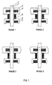
- Fig. 1 shows a schematic diagram of a first preferred embodiment of the drive device according to the invention.
- the drive device is shown as a piezo-linear step drive, wherein an elongated body 1 a on a housing (not shown) of the drive device fixed receiving device 2 in a first plane perpendicular to the elongated body 1 and a movable with respect to the housing receiving device 3 in a second Plane are arranged perpendicular to the elongated body 1.
- the receiving devices 2 and 3 respectively holding devices 4 and 5 are provided, which are designed as clamping piezo elements.
- Axially to the elongated body 1 and between the receiving devices 2 and 3 and in each case connected to these is designed as acting piezoelectric elements moving means 6 is provided.
- PHASE 1 to PHASE 4 the drive device are shown.
- PHASE 1 If only the first holding device 4 holds the elongate body 1, in a second drive phase, the PHASE 2, both the first holding device 4 and the second holding device 5 hold the elongate body 1; in a third drive phase, the PHASE 3 holds only the second holding device 5, the elongate body 1, while the moving means 6 moves the elongate body 1 via the movable receiving means 3 and the second holding means 5, and in a fourth driving phase, the PHASE 4, holding the elongated body 1, the second holding means 5 holds the elongated body Body 1 is no longer and again holds only the first holding device 4, the elongated body 1.
- a movement of the elongated body 1 in the direction of the movable receiving device 3, as in Fig. 1 by a mark 7 on the elongated body 1 is displayed.
- the holding devices 4 and 5 are clamping piezoelectric elements according to this first embodiment, wherein it is possible that the clamping piezoelectric elements reach their maximum length without current, so that no holding current is necessary. It is also possible that the clamping piezoelectric elements reach their minimum length without current, so that no current is necessary if the clamping piezo elements do not hold the elongated body.
- the piezoelectric elements 4, 5, 6 provided according to FIG. 1 are preferably arranged, as will be described in more detail below with reference to FIGS. 2A and 2B.
- Fig. 2A at least two clamping piezo elements of the first and second holding means 4 and 5 are respectively disposed so as to be fixed radially inwardly toward the elongate body 1 to the fixed receiving means 2 and the movable receiving means 3 and from the elongated body 1 arranged from under a respective same angle in a plane are.
- the clamping piezo elements of the first holding device 2 and the clamping piezo elements of the second holding device 3 are preferably arranged offset with respect to each other with respect to their angle.
- At least two clamping piezo elements of the first and the second holding device 2 'and 3' may be arranged such that they are each parallel to one another at an intermediate piece 8 provided in the direction of the elongated body 1 ' 'are arranged on the fixed receiving device 2' and the movable receiving device 3 '.
- At least two acting piezo elements of the moving means 6 or 6 ' are arranged to extend in the longitudinal direction of the elongate body 1 or 1' between the fixed receiving means 2 or 2 'and the movable receiving means 3 or 3' ,
- a compact design of the drive device can be achieved.
- FIG. 3 shows a schematic representation of a drive device according to the present invention, wherein an elongate body 11, of which only one (right) longitudinal side is shown, is provided with a toothing 13.
- the elongated body 11 extends within a fixed to the drive frame 12.
- individual teeth 14 are provided, which are attached to respective attached to the frame 12 piezo elements 20, 21, ..., 29 and the teeth 13 of the elongated Body 11 are opposite.
- the toothing 13 has one tooth less than piezo elements 20, 21,..., 29 with teeth 14 are provided.
- the holding device and the movement device of the invention thus correspond to the toothing 13 and the teeth 14 on the piezo elements 20, 21,..., 29 of the drive device shown in FIG.
- FIG. 3 different drive phases, PHASE 0 to 9, of the drive device are shown by way of example.
- the teeth 14 and the teeth 13 do not touch each other in a rest position.
- PHASE 0 a first tooth 14 engages an opposing tooth space of the toothing 13 by being extended by the associated piezo element 20 from the frame 12, so that the elongated body 11 is held.
- the teeth 14 are extended by respectively associated piezoelectric elements 21, ..., 29 consecutively from the frame 12 and brought into engagement with respective tooth gaps of the teeth 13, so that the elongate body 11 due to the different numbers of teeth 14 and Teeth of the toothing 13 and the resulting gradient difference between the teeth 14 and the teeth 13, a movement of the elongated body 11 takes place.
- the drive phases PHASE 1, PHASE 5 and PHASE 9 are shown, wherein the mark 17 indicates that the elongated body 11 is here moved towards the tooth 14 with the associated piezoelectric element 20.
- At least one tooth 14 must always be in engagement with a tooth gap of the toothing. It may therefore only be withdrawn during driving when a next tooth 14 is already almost completely in engagement with the toothing 13.
- the teeth 14 need not be formed as individual elements, as shown in Fig. 3, but they can also be formed as a deformable rack, from which then the respective tooth elements through the piezo elements 20, 21, ..., 29 toward the teeth 13 are brought.
- a plurality of frames 12 with piezo elements 20, 21,..., 29 and associated teeth 14 may be arranged around the elongated body 11 so as to be slightly along its longitudinal axis are offset, wherein an actuation of piezo elements 20, 21, ..., 29 takes place around the teeth 14 in engagement with tooth gaps of the toothing 13 of the frame 12 to frame 12.
- moving and / or holding by a piezoelectric element can be carried out without current.
- high switching speeds and high spatial resolution can be achieved.
- the elongated body may be a valve lifter for various valves, such as seat, diaphragm and special valves, a cylinder for actuating a device or a slider.
- the drive device according to the invention using piezoelectric elements pressure generator stations can be saved. Furthermore, it is possible that advantages in terms of movement speeds, i. in the case of use of the elongated body as a valve tappet adjustment and closing speeds can be achieved.
- the drive device can be made relatively small. In particular, according to the second embodiment, a very accurate positioning is made possible. Furthermore, an electroless holding and / or moving is also possible. This can reduce power consumption and power consumption.
- the present invention provides a drive device of simple construction which can accurately and quickly move and position elongated bodies.
Landscapes
- General Electrical Machinery Utilizing Piezoelectricity, Electrostriction Or Magnetostriction (AREA)
- Advancing Webs (AREA)
- Vehicle Body Suspensions (AREA)
- Transmission Devices (AREA)
- Electrically Driven Valve-Operating Means (AREA)
Applications Claiming Priority (1)
| Application Number | Priority Date | Filing Date | Title |
|---|---|---|---|
| DE102005033455A DE102005033455A1 (de) | 2005-07-18 | 2005-07-18 | Antriebsvorrichtung zum linearen Bewegen von länglichen Körpern |
Publications (3)
| Publication Number | Publication Date |
|---|---|
| EP1746668A2 true EP1746668A2 (fr) | 2007-01-24 |
| EP1746668A3 EP1746668A3 (fr) | 2009-01-28 |
| EP1746668B1 EP1746668B1 (fr) | 2009-11-11 |
Family
ID=37397511
Family Applications (1)
| Application Number | Title | Priority Date | Filing Date |
|---|---|---|---|
| EP06014772A Not-in-force EP1746668B1 (fr) | 2005-07-18 | 2006-07-15 | Dispositif d'entraînement pour deplacer linéairement des corps oblongs |
Country Status (4)
| Country | Link |
|---|---|
| US (1) | US20080001498A1 (fr) |
| EP (1) | EP1746668B1 (fr) |
| AT (1) | ATE448574T1 (fr) |
| DE (2) | DE102005033455A1 (fr) |
Cited By (2)
| Publication number | Priority date | Publication date | Assignee | Title |
|---|---|---|---|---|
| EP2112759A3 (fr) * | 2008-04-21 | 2011-09-07 | Helmut Wurm | Moteur piézoélectrique |
| WO2012022443A1 (fr) * | 2010-08-20 | 2012-02-23 | Aspre Ag | Moteur piézoélectrique |
Families Citing this family (25)
| Publication number | Priority date | Publication date | Assignee | Title |
|---|---|---|---|---|
| US8274039B2 (en) | 2008-11-13 | 2012-09-25 | Zena Technologies, Inc. | Vertical waveguides with various functionality on integrated circuits |
| US9000353B2 (en) | 2010-06-22 | 2015-04-07 | President And Fellows Of Harvard College | Light absorption and filtering properties of vertically oriented semiconductor nano wires |
| US8519379B2 (en) | 2009-12-08 | 2013-08-27 | Zena Technologies, Inc. | Nanowire structured photodiode with a surrounding epitaxially grown P or N layer |
| US8890271B2 (en) | 2010-06-30 | 2014-11-18 | Zena Technologies, Inc. | Silicon nitride light pipes for image sensors |
| US8299472B2 (en) | 2009-12-08 | 2012-10-30 | Young-June Yu | Active pixel sensor with nanowire structured photodetectors |
| US8269985B2 (en) | 2009-05-26 | 2012-09-18 | Zena Technologies, Inc. | Determination of optimal diameters for nanowires |
| US8866065B2 (en) | 2010-12-13 | 2014-10-21 | Zena Technologies, Inc. | Nanowire arrays comprising fluorescent nanowires |
| US9082673B2 (en) | 2009-10-05 | 2015-07-14 | Zena Technologies, Inc. | Passivated upstanding nanostructures and methods of making the same |
| US9478685B2 (en) | 2014-06-23 | 2016-10-25 | Zena Technologies, Inc. | Vertical pillar structured infrared detector and fabrication method for the same |
| US8889455B2 (en) | 2009-12-08 | 2014-11-18 | Zena Technologies, Inc. | Manufacturing nanowire photo-detector grown on a back-side illuminated image sensor |
| US8384007B2 (en) | 2009-10-07 | 2013-02-26 | Zena Technologies, Inc. | Nano wire based passive pixel image sensor |
| US9406709B2 (en) | 2010-06-22 | 2016-08-02 | President And Fellows Of Harvard College | Methods for fabricating and using nanowires |
| US8507840B2 (en) | 2010-12-21 | 2013-08-13 | Zena Technologies, Inc. | Vertically structured passive pixel arrays and methods for fabricating the same |
| US8735797B2 (en) | 2009-12-08 | 2014-05-27 | Zena Technologies, Inc. | Nanowire photo-detector grown on a back-side illuminated image sensor |
| US8791470B2 (en) | 2009-10-05 | 2014-07-29 | Zena Technologies, Inc. | Nano structured LEDs |
| US8229255B2 (en) | 2008-09-04 | 2012-07-24 | Zena Technologies, Inc. | Optical waveguides in image sensors |
| US9343490B2 (en) | 2013-08-09 | 2016-05-17 | Zena Technologies, Inc. | Nanowire structured color filter arrays and fabrication method of the same |
| US8835831B2 (en) | 2010-06-22 | 2014-09-16 | Zena Technologies, Inc. | Polarized light detecting device and fabrication methods of the same |
| US9299866B2 (en) | 2010-12-30 | 2016-03-29 | Zena Technologies, Inc. | Nanowire array based solar energy harvesting device |
| US8546742B2 (en) | 2009-06-04 | 2013-10-01 | Zena Technologies, Inc. | Array of nanowires in a single cavity with anti-reflective coating on substrate |
| US8748799B2 (en) | 2010-12-14 | 2014-06-10 | Zena Technologies, Inc. | Full color single pixel including doublet or quadruplet si nanowires for image sensors |
| US9515218B2 (en) | 2008-09-04 | 2016-12-06 | Zena Technologies, Inc. | Vertical pillar structured photovoltaic devices with mirrors and optical claddings |
| NL1038896C2 (en) * | 2011-06-24 | 2013-01-02 | Janssen Prec Engineering B V | Inertial drive system with friction release. |
| EP2853106A4 (fr) | 2012-05-23 | 2015-12-23 | Nokia Technologies Oy | Procédé et appareil de dérivation de clé pour un accès local sous la commande d'un réseau cellulaire |
| CN103701359B (zh) * | 2013-12-09 | 2015-09-16 | 浙江大学 | 一种基于压电堆的压电振动冲击的旋转电机 |
Citations (1)
| Publication number | Priority date | Publication date | Assignee | Title |
|---|---|---|---|---|
| JPH0538165A (ja) | 1991-07-25 | 1993-02-12 | Matsushita Electric Works Ltd | 直線駆動型圧電モータ |
Family Cites Families (13)
| Publication number | Priority date | Publication date | Assignee | Title |
|---|---|---|---|---|
| US3644764A (en) * | 1967-08-30 | 1972-02-22 | Mesur Matic Electronics Corp | Harmonic drive for digital step motor |
| DE3040563A1 (de) * | 1980-10-28 | 1982-05-27 | Siemens AG, 1000 Berlin und 8000 München | Elektrisch zu betaetigendes stellglied |
| JPS6348168A (ja) * | 1986-08-14 | 1988-02-29 | Fuji Elelctrochem Co Ltd | 圧電アクチユエ−タ |
| US4971106A (en) * | 1987-09-30 | 1990-11-20 | Toto, Ltd. | Automatically operating valve for regulating water flow and faucet provided with said valve |
| DE3937020A1 (de) * | 1989-11-07 | 1991-05-08 | Du Pont Deutschland | Verfahren und vorrichtung fuer den linearen transport bahn- und blattfoermiger materialien |
| JPH04372324A (ja) * | 1991-06-21 | 1992-12-25 | Toyoda Mach Works Ltd | 送り装置 |
| JP2880837B2 (ja) * | 1991-11-15 | 1999-04-12 | 松下電工株式会社 | 平面駆動型圧電モータ |
| CA2081094A1 (fr) * | 1992-02-18 | 1993-08-19 | Gordon Walter Culp | Actionneur dente |
| DE4315238A1 (de) * | 1993-05-07 | 1994-11-17 | Physik Instr Pi Gmbh & Co | Verstelleinrichtung mit Piezoantrieb |
| DE4329163A1 (de) * | 1993-08-30 | 1995-03-02 | Stm Medtech Starnberg | Piezoelektrische Antriebseinheit |
| DE19746609A1 (de) * | 1997-06-23 | 1999-03-11 | Koenig Wilhelm | Rotatorischer, translatorischer Piezoantrieb |
| US6882084B2 (en) * | 2003-06-13 | 2005-04-19 | Piezomotor Uppsala Ab | Electromagnetic drive unit |
| US7161278B2 (en) * | 2003-10-31 | 2007-01-09 | Piezomotor Uppsala Ab | Peristaltic electromechanical actuator |
-
2005
- 2005-07-18 DE DE102005033455A patent/DE102005033455A1/de not_active Withdrawn
-
2006
- 2006-07-15 DE DE502006005318T patent/DE502006005318D1/de active Active
- 2006-07-15 AT AT06014772T patent/ATE448574T1/de active
- 2006-07-15 EP EP06014772A patent/EP1746668B1/fr not_active Not-in-force
- 2006-07-18 US US11/458,127 patent/US20080001498A1/en not_active Abandoned
Patent Citations (1)
| Publication number | Priority date | Publication date | Assignee | Title |
|---|---|---|---|---|
| JPH0538165A (ja) | 1991-07-25 | 1993-02-12 | Matsushita Electric Works Ltd | 直線駆動型圧電モータ |
Cited By (4)
| Publication number | Priority date | Publication date | Assignee | Title |
|---|---|---|---|---|
| EP2112759A3 (fr) * | 2008-04-21 | 2011-09-07 | Helmut Wurm | Moteur piézoélectrique |
| WO2012022443A1 (fr) * | 2010-08-20 | 2012-02-23 | Aspre Ag | Moteur piézoélectrique |
| RU2556027C2 (ru) * | 2010-08-20 | 2015-07-10 | Аспре Аг | Пьезомотор |
| US9118263B2 (en) | 2010-08-20 | 2015-08-25 | Aspre Ag | Piezo motor |
Also Published As
| Publication number | Publication date |
|---|---|
| DE502006005318D1 (de) | 2009-12-24 |
| EP1746668A3 (fr) | 2009-01-28 |
| EP1746668B1 (fr) | 2009-11-11 |
| US20080001498A1 (en) | 2008-01-03 |
| DE102005033455A1 (de) | 2007-01-25 |
| ATE448574T1 (de) | 2009-11-15 |
Similar Documents
| Publication | Publication Date | Title |
|---|---|---|
| EP1746668A2 (fr) | Dispositif d'entraînement pour deplacer linéairement des corps oblongs | |
| DE102007061353A1 (de) | Ventiltrieb für Gaswechselventile einer Brennkraftmaschine mit einem verschiebbarem Nockenträger mit Endlosnut | |
| DE202015009047U1 (de) | Ventiltrieb für eine Brennkraftmaschine | |
| DE102013010330B4 (de) | Nockenwelle und Verfahren zur Montage einer solchen Nockenwelle | |
| DE102007037358A1 (de) | Schaltvorrichtung | |
| DE202017003037U1 (de) | Präzisionsspannfutter mit bogenförmigen Schienen | |
| DE112013007022T5 (de) | Bewegungsmechanismus und Außenspiegel für ein Fahrzeug, der mit einem solchen Bewegungsmechanismus ausgestattet ist | |
| EP2739830A1 (fr) | Commande de soupape d'un moteur à combustion interne, moteur à combustion interne et procédé de fabrication d'une commande de soupape correspondante | |
| DE60032350T2 (de) | Verstellbare ventilsteurungseinrichtung und verfahren | |
| DE19930434B4 (de) | Stellglied | |
| DE102016210976A1 (de) | Ventiltrieb für eine Brennkraftmaschine | |
| EP3332099B1 (fr) | Distribution pour un moteur à combustion interne | |
| DE102014217584B4 (de) | Ventiltriebvorrichtung sowie Schaltkulisse | |
| DE2821635A1 (de) | Hubvorrichtung | |
| DE102007036336A1 (de) | Getriebesteller zum Betätigen einer Schalteinrichtung eines Getriebes | |
| WO2018087242A1 (fr) | Mécanisme de distribution pour un moteur à combustion interne | |
| DE2709592C2 (de) | Vorrichtung zum Drehen und Transportieren der Muttern mehrerer auf einem Lochkreis angeordneter Schraubenbolzen | |
| DE102017113751A1 (de) | Greifvorrichtung und Klemmeinheit | |
| DE2622744B2 (de) | Einrichtung zur Einstellung des Zahnflankenspiels in druckmittelbetriebenen Schwenkmotoren | |
| DE2260533B2 (de) | Regelgestänge zur Fördermengenverstellung mehrerer in Reihe hintereinander angeordneter Kraftstoffeinspritzpumpen | |
| DE102013104642A1 (de) | Elektromagnetische Stellvorrichtung, Verwendung einer solchen elektromagnetischen Stellvorrichtung und System aufweisend eine solche elektromagnetische Stellvorrichtung | |
| DE102013204655A1 (de) | Ventiltrieb eines Verbrennungsmotors | |
| DE102018209397A1 (de) | Ventilantriebsvorrichtung mit Umschalteinrichtung | |
| DE102019110715A1 (de) | Ventiltrieb einer Brennkraftmaschine und Verfahren zum Vermeiden von Fehlschaltungen an einem schaltbaren Ventiltrieb | |
| DE765144C (de) | Nockenschaltwalze |
Legal Events
| Date | Code | Title | Description |
|---|---|---|---|
| PUAI | Public reference made under article 153(3) epc to a published international application that has entered the european phase |
Free format text: ORIGINAL CODE: 0009012 |
|
| AK | Designated contracting states |
Kind code of ref document: A2 Designated state(s): AT BE BG CH CY CZ DE DK EE ES FI FR GB GR HU IE IS IT LI LT LU LV MC NL PL PT RO SE SI SK TR |
|
| AX | Request for extension of the european patent |
Extension state: AL BA HR MK YU |
|
| PUAL | Search report despatched |
Free format text: ORIGINAL CODE: 0009013 |
|
| AK | Designated contracting states |
Kind code of ref document: A3 Designated state(s): AT BE BG CH CY CZ DE DK EE ES FI FR GB GR HU IE IS IT LI LT LU LV MC NL PL PT RO SE SI SK TR |
|
| AX | Request for extension of the european patent |
Extension state: AL BA HR MK RS |
|
| 17P | Request for examination filed |
Effective date: 20090213 |
|
| 17Q | First examination report despatched |
Effective date: 20090331 |
|
| GRAP | Despatch of communication of intention to grant a patent |
Free format text: ORIGINAL CODE: EPIDOSNIGR1 |
|
| AKX | Designation fees paid |
Designated state(s): AT BE BG CH CY CZ DE DK EE ES FI FR GB GR HU IE IS IT LI LT LU LV MC NL PL PT RO SE SI SK TR |
|
| GRAS | Grant fee paid |
Free format text: ORIGINAL CODE: EPIDOSNIGR3 |
|
| GRAA | (expected) grant |
Free format text: ORIGINAL CODE: 0009210 |
|
| AK | Designated contracting states |
Kind code of ref document: B1 Designated state(s): AT BE BG CH CY CZ DE DK EE ES FI FR GB GR HU IE IS IT LI LT LU LV MC NL PL PT RO SE SI SK TR |
|
| REG | Reference to a national code |
Ref country code: GB Ref legal event code: FG4D Free format text: NOT ENGLISH |
|
| REG | Reference to a national code |
Ref country code: CH Ref legal event code: EP |
|
| REG | Reference to a national code |
Ref country code: IE Ref legal event code: FG4D |
|
| REF | Corresponds to: |
Ref document number: 502006005318 Country of ref document: DE Date of ref document: 20091224 Kind code of ref document: P |
|
| NLV1 | Nl: lapsed or annulled due to failure to fulfill the requirements of art. 29p and 29m of the patents act | ||
| LTIE | Lt: invalidation of european patent or patent extension |
Effective date: 20091111 |
|
| PG25 | Lapsed in a contracting state [announced via postgrant information from national office to epo] |
Ref country code: FI Free format text: LAPSE BECAUSE OF FAILURE TO SUBMIT A TRANSLATION OF THE DESCRIPTION OR TO PAY THE FEE WITHIN THE PRESCRIBED TIME-LIMIT Effective date: 20091111 Ref country code: LT Free format text: LAPSE BECAUSE OF FAILURE TO SUBMIT A TRANSLATION OF THE DESCRIPTION OR TO PAY THE FEE WITHIN THE PRESCRIBED TIME-LIMIT Effective date: 20091111 Ref country code: SE Free format text: LAPSE BECAUSE OF FAILURE TO SUBMIT A TRANSLATION OF THE DESCRIPTION OR TO PAY THE FEE WITHIN THE PRESCRIBED TIME-LIMIT Effective date: 20091111 Ref country code: PT Free format text: LAPSE BECAUSE OF FAILURE TO SUBMIT A TRANSLATION OF THE DESCRIPTION OR TO PAY THE FEE WITHIN THE PRESCRIBED TIME-LIMIT Effective date: 20100311 Ref country code: ES Free format text: LAPSE BECAUSE OF FAILURE TO SUBMIT A TRANSLATION OF THE DESCRIPTION OR TO PAY THE FEE WITHIN THE PRESCRIBED TIME-LIMIT Effective date: 20100222 Ref country code: IS Free format text: LAPSE BECAUSE OF FAILURE TO SUBMIT A TRANSLATION OF THE DESCRIPTION OR TO PAY THE FEE WITHIN THE PRESCRIBED TIME-LIMIT Effective date: 20100311 |
|
| PG25 | Lapsed in a contracting state [announced via postgrant information from national office to epo] |
Ref country code: LV Free format text: LAPSE BECAUSE OF FAILURE TO SUBMIT A TRANSLATION OF THE DESCRIPTION OR TO PAY THE FEE WITHIN THE PRESCRIBED TIME-LIMIT Effective date: 20091111 Ref country code: CY Free format text: LAPSE BECAUSE OF FAILURE TO SUBMIT A TRANSLATION OF THE DESCRIPTION OR TO PAY THE FEE WITHIN THE PRESCRIBED TIME-LIMIT Effective date: 20091111 Ref country code: SI Free format text: LAPSE BECAUSE OF FAILURE TO SUBMIT A TRANSLATION OF THE DESCRIPTION OR TO PAY THE FEE WITHIN THE PRESCRIBED TIME-LIMIT Effective date: 20091111 Ref country code: PL Free format text: LAPSE BECAUSE OF FAILURE TO SUBMIT A TRANSLATION OF THE DESCRIPTION OR TO PAY THE FEE WITHIN THE PRESCRIBED TIME-LIMIT Effective date: 20091111 |
|
| REG | Reference to a national code |
Ref country code: IE Ref legal event code: FD4D |
|
| PG25 | Lapsed in a contracting state [announced via postgrant information from national office to epo] |
Ref country code: RO Free format text: LAPSE BECAUSE OF FAILURE TO SUBMIT A TRANSLATION OF THE DESCRIPTION OR TO PAY THE FEE WITHIN THE PRESCRIBED TIME-LIMIT Effective date: 20091111 Ref country code: BG Free format text: LAPSE BECAUSE OF FAILURE TO SUBMIT A TRANSLATION OF THE DESCRIPTION OR TO PAY THE FEE WITHIN THE PRESCRIBED TIME-LIMIT Effective date: 20100211 Ref country code: DK Free format text: LAPSE BECAUSE OF FAILURE TO SUBMIT A TRANSLATION OF THE DESCRIPTION OR TO PAY THE FEE WITHIN THE PRESCRIBED TIME-LIMIT Effective date: 20091111 Ref country code: EE Free format text: LAPSE BECAUSE OF FAILURE TO SUBMIT A TRANSLATION OF THE DESCRIPTION OR TO PAY THE FEE WITHIN THE PRESCRIBED TIME-LIMIT Effective date: 20091111 Ref country code: IE Free format text: LAPSE BECAUSE OF FAILURE TO SUBMIT A TRANSLATION OF THE DESCRIPTION OR TO PAY THE FEE WITHIN THE PRESCRIBED TIME-LIMIT Effective date: 20091111 |
|
| PG25 | Lapsed in a contracting state [announced via postgrant information from national office to epo] |
Ref country code: CZ Free format text: LAPSE BECAUSE OF FAILURE TO SUBMIT A TRANSLATION OF THE DESCRIPTION OR TO PAY THE FEE WITHIN THE PRESCRIBED TIME-LIMIT Effective date: 20091111 Ref country code: SK Free format text: LAPSE BECAUSE OF FAILURE TO SUBMIT A TRANSLATION OF THE DESCRIPTION OR TO PAY THE FEE WITHIN THE PRESCRIBED TIME-LIMIT Effective date: 20091111 |
|
| PLBE | No opposition filed within time limit |
Free format text: ORIGINAL CODE: 0009261 |
|
| STAA | Information on the status of an ep patent application or granted ep patent |
Free format text: STATUS: NO OPPOSITION FILED WITHIN TIME LIMIT |
|
| 26N | No opposition filed |
Effective date: 20100812 |
|
| PG25 | Lapsed in a contracting state [announced via postgrant information from national office to epo] |
Ref country code: GR Free format text: LAPSE BECAUSE OF FAILURE TO SUBMIT A TRANSLATION OF THE DESCRIPTION OR TO PAY THE FEE WITHIN THE PRESCRIBED TIME-LIMIT Effective date: 20100212 |
|
| BERE | Be: lapsed |
Owner name: GEMU GEBRUDER MULLER APPARATEBAU G.M.B.H. & CO. KG Effective date: 20100731 |
|
| PG25 | Lapsed in a contracting state [announced via postgrant information from national office to epo] |
Ref country code: MC Free format text: LAPSE BECAUSE OF NON-PAYMENT OF DUE FEES Effective date: 20100731 |
|
| REG | Reference to a national code |
Ref country code: CH Ref legal event code: PL |
|
| GBPC | Gb: european patent ceased through non-payment of renewal fee |
Effective date: 20100715 |
|
| PG25 | Lapsed in a contracting state [announced via postgrant information from national office to epo] |
Ref country code: IT Free format text: LAPSE BECAUSE OF FAILURE TO SUBMIT A TRANSLATION OF THE DESCRIPTION OR TO PAY THE FEE WITHIN THE PRESCRIBED TIME-LIMIT Effective date: 20091111 |
|
| REG | Reference to a national code |
Ref country code: FR Ref legal event code: ST Effective date: 20110331 |
|
| PG25 | Lapsed in a contracting state [announced via postgrant information from national office to epo] |
Ref country code: LI Free format text: LAPSE BECAUSE OF NON-PAYMENT OF DUE FEES Effective date: 20100731 Ref country code: CH Free format text: LAPSE BECAUSE OF NON-PAYMENT OF DUE FEES Effective date: 20100731 |
|
| PG25 | Lapsed in a contracting state [announced via postgrant information from national office to epo] |
Ref country code: FR Free format text: LAPSE BECAUSE OF NON-PAYMENT OF DUE FEES Effective date: 20100802 |
|
| PG25 | Lapsed in a contracting state [announced via postgrant information from national office to epo] |
Ref country code: BE Free format text: LAPSE BECAUSE OF NON-PAYMENT OF DUE FEES Effective date: 20100731 |
|
| PG25 | Lapsed in a contracting state [announced via postgrant information from national office to epo] |
Ref country code: GB Free format text: LAPSE BECAUSE OF NON-PAYMENT OF DUE FEES Effective date: 20100715 |
|
| PG25 | Lapsed in a contracting state [announced via postgrant information from national office to epo] |
Ref country code: HU Free format text: LAPSE BECAUSE OF FAILURE TO SUBMIT A TRANSLATION OF THE DESCRIPTION OR TO PAY THE FEE WITHIN THE PRESCRIBED TIME-LIMIT Effective date: 20100512 Ref country code: LU Free format text: LAPSE BECAUSE OF NON-PAYMENT OF DUE FEES Effective date: 20100715 Ref country code: NL Free format text: LAPSE BECAUSE OF FAILURE TO SUBMIT A TRANSLATION OF THE DESCRIPTION OR TO PAY THE FEE WITHIN THE PRESCRIBED TIME-LIMIT Effective date: 20091111 |
|
| PG25 | Lapsed in a contracting state [announced via postgrant information from national office to epo] |
Ref country code: TR Free format text: LAPSE BECAUSE OF FAILURE TO SUBMIT A TRANSLATION OF THE DESCRIPTION OR TO PAY THE FEE WITHIN THE PRESCRIBED TIME-LIMIT Effective date: 20091111 |
|
| REG | Reference to a national code |
Ref country code: AT Ref legal event code: MM01 Ref document number: 448574 Country of ref document: AT Kind code of ref document: T Effective date: 20110715 |
|
| PG25 | Lapsed in a contracting state [announced via postgrant information from national office to epo] |
Ref country code: AT Free format text: LAPSE BECAUSE OF NON-PAYMENT OF DUE FEES Effective date: 20110715 |
|
| PGFP | Annual fee paid to national office [announced via postgrant information from national office to epo] |
Ref country code: DE Payment date: 20140919 Year of fee payment: 9 |
|
| REG | Reference to a national code |
Ref country code: DE Ref legal event code: R119 Ref document number: 502006005318 Country of ref document: DE |
|
| PG25 | Lapsed in a contracting state [announced via postgrant information from national office to epo] |
Ref country code: DE Free format text: LAPSE BECAUSE OF NON-PAYMENT OF DUE FEES Effective date: 20160202 |