EP1746668B1 - Antriebsvorrichtung zum linearen Bewegen von länglichen Körpern - Google Patents
Antriebsvorrichtung zum linearen Bewegen von länglichen Körpern Download PDFInfo
- Publication number
- EP1746668B1 EP1746668B1 EP06014772A EP06014772A EP1746668B1 EP 1746668 B1 EP1746668 B1 EP 1746668B1 EP 06014772 A EP06014772 A EP 06014772A EP 06014772 A EP06014772 A EP 06014772A EP 1746668 B1 EP1746668 B1 EP 1746668B1
- Authority
- EP
- European Patent Office
- Prior art keywords
- elongated body
- gear tooth
- teeth
- tooth system
- individual teeth
- Prior art date
- Legal status (The legal status is an assumption and is not a legal conclusion. Google has not performed a legal analysis and makes no representation as to the accuracy of the status listed.)
- Not-in-force
Links
Images
Classifications
-
- H—ELECTRICITY
- H02—GENERATION; CONVERSION OR DISTRIBUTION OF ELECTRIC POWER
- H02N—ELECTRIC MACHINES NOT OTHERWISE PROVIDED FOR
- H02N2/00—Electric machines in general using piezoelectric effect, electrostriction or magnetostriction
- H02N2/02—Electric machines in general using piezoelectric effect, electrostriction or magnetostriction producing linear motion, e.g. actuators; Linear positioners ; Linear motors
- H02N2/021—Electric machines in general using piezoelectric effect, electrostriction or magnetostriction producing linear motion, e.g. actuators; Linear positioners ; Linear motors using intermittent driving, e.g. step motors, piezoleg motors
- H02N2/023—Inchworm motors
Definitions
- the invention relates to a drive device for linearly moving elongate bodies, such as valve tappets for various valves, such as seat, diaphragm and special valves, cylinders for actuating devices or slides, according to the features of the preamble of claim 1.
- the drive device is designed as a piezo drive. It has a holding device for holding the elongate body at its periphery during a resting state and / or during a movement state and a movement device.
- the movement means causes a movement of the elongated body in his Longitudinal axis.
- the holding device and the movement device each have piezo elements.
- the holding device and the movement device have a toothing formed on the elongate body and within a frame fixed to the drive device, in which the elongate body extends, mounted individual provided on respective piezoelectric elements teeth which are opposite to the toothing, wherein the toothing has a tooth less , as piezo elements are provided with teeth.
- a plurality of frames having piezo elements and associated teeth are disposed around the elongate body for reducing the pitch intervals so as to be slightly offset along its longitudinal axis, wherein actuation of piezo elements to bring teeth into engagement with tooth spaces of the teeth of the frame Frame is done.
- the teeth and the teeth do not touch each other in a rest position, and in an initial position, a first tooth engages an opposing tooth space of the teeth by being extended by the associated piezo element from the respective frame so as to hold the elongate body, and further the teeth are sequentially extended by the respective associated piezoelectric elements from the frame and brought into engagement with respective tooth gaps of the toothing, so that due to the different number of teeth and teeth of the teeth and the resulting difference in pitch between the teeth and the teeth movement of the elongated body takes place.
- the drive device also has a control and switching device for the desired activation and deactivation of the piezoelectric elements.
- the elongated body In particular, it may be a valve lifter for various valves, such as seat, diaphragm and special valves, a cylinder for actuating a device or a slider.
- the drive device can be made relatively small. A very accurate positioning of the elongated body is made possible. Furthermore, electroless holding and / or moving is also enabled, whereby power consumption can be reduced.
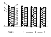
- the drawing shows a schematic diagram of a drive device according to the present invention, wherein an elongate body 11, of which only one (right) longitudinal side is shown, is provided with a toothing 13.
- the elongated body 11 extends within a fixed to the drive frame 12.
- individual teeth 14 are provided, which are attached to respective attached to the frame 12 piezo elements 20, 21, ..., 29 and the teeth 13 of the elongated Body 11 are opposite.
- the toothing 13 has one tooth less than piezo elements 20, 21,..., 29 with teeth 14 are provided.
- the holding device and the movement device of the invention thus correspond to the toothing 13 and the teeth 14 on the piezo elements 20, 21,..., 29 of the illustrated drive device.
- PHASE 0 to 9 Different drive phases, PHASE 0 to 9, of the drive device are shown by way of example in the drawing.
- the teeth 14 and the teeth 13 do not touch each other in a rest position.
- PHASE 0 a first tooth 14 engages an opposing tooth space of the toothing 13 by being extended by the associated piezo element 20 from the frame 12, so that the elongated body 11 is held.
- the teeth 14 are extended by respectively associated piezoelectric elements 21, ..., 29 consecutively from the frame 12 and brought into engagement with respective tooth gaps of the teeth 13, so that the elongate body 11 due to the different numbers of teeth 14 and Teeth of the toothing 13 and the resulting gradient difference between the teeth 14 and the teeth 13, a movement of the elongated body 11 takes place.
- the drive phases PHASE 1, PHASE 5 and PHASE 9 are shown, wherein the mark 17 indicates that the elongated body 11 is here moved towards the tooth 14 with the associated piezoelectric element 20.
- At least one tooth 14 must always be in engagement with a tooth gap of the toothing. It may therefore only be withdrawn during driving when a next tooth 14 is already almost completely in engagement with the toothing 13.
- the teeth 14 need not be formed as individual elements, as shown in the drawing, but they can also be formed as a deformable rack, from which then the respective tooth elements through the piezo elements 20, 21, ..., 29 toward the Teeth 13 are brought.
- a plurality of frames 12 with piezo elements 20, 21, ..., 29 and associated teeth 14 about the elongated body 11 are arranged so that they are slightly offset along its longitudinal axis, wherein an actuation of piezoelectric elements 20, 21,. .., 29 takes place to the teeth 14 in engagement with tooth gaps of the teeth 13 of the frame 12 to frame 12 takes place.
- moving and / or holding by a piezoelectric element can be carried out without current. According to this embodiment, high switching speeds and high spatial resolution can be achieved.
- the elongated body may be a valve lifter for various valves, such as seat, diaphragm and special valves, a cylinder for actuating a device or a slider.
- the Drive device using piezoelectric elements pressure generator stations can be saved. Furthermore, it is possible that advantages in terms of movement speeds, ie in the case of use of the elongated body as a valve tappet adjusting and closing speeds, can be achieved.
- the Drive device can be made relatively small. In particular, a very accurate positioning is possible. Furthermore, an electroless holding and / or moving is also possible. This can reduce power consumption and power consumption.
- the present invention provides a drive device of simple construction which can accurately and quickly move and position elongated bodies.
Landscapes
- General Electrical Machinery Utilizing Piezoelectricity, Electrostriction Or Magnetostriction (AREA)
- Electrically Driven Valve-Operating Means (AREA)
- Advancing Webs (AREA)
- Vehicle Body Suspensions (AREA)
- Transmission Devices (AREA)
Description
- Die Erfindung betrifft eine Antriebsvorrichtung zum linearen Bewegen von länglichen Körpern, wie beispielsweise Ventilstößel für verschiedene Ventile, wie Sitz-, Membran- und Sonderventile, Zylinder zur Betätigung von Vorrichtungen oder Schieber, gemäß den Merkmalen des Oberbegriffs des Anspruchs 1.
- Herkömmlich werden längliche Körper hauptsächlich pneumatisch betrieben. In Zusammenhang mit möglichen Einsparungen von Druckerzeugerstationen stellt sich aber die Frage nach alternativen Antriebskonzepten. Aus der
JP 05 038165 - Es ist somit eine Aufgabe der Erfindung, eine Antriebsvorrichtung zum linearen Bewegen von länglichen Körpern zur Verfügung zu stellen, die kleine Verstellintervalle aufweist.
- Diese Aufgabe wird erfindungsgemäß durch die im Anspruch 1 angegebene Antriebsvorrichtung gelöst. Die abhängigen Ansprüche 2 bis 4 zeigen spezielle Ausführungsformen der Antriebsvorrichtung gemäß Anspruch 1.
- Die erfindungsgemäße Antriebsvorrichtung ist als Piezoantrieb ausgebildet. Sie weist eine Halteeinrichtung zum Halten des länglichen Körpers an seinem Umfang während eines Ruhezustands und/oder während eines Bewegungszustands und eine Bewegungseinrichtung auf. Die Bewegungseinrichtung veranlasst eine Bewegung des länglichen Körpers in seiner Längsachsenrichtung. Insbesondere weisen die Halteeinrichtung und die Bewegungseinrichtung jeweils Piezoelemente auf.
- Dabei weisen die Halteeinrichtung und die Bewegungseinrichtung eine am länglichen Körper ausgebildete Verzahnung und innerhalb eines an der Antriebsvorrichtung fixierten Rahmens, in welchem der längliche Körper verläuft, gelagerte einzelne an jeweiligen Piezoelementen vorgesehene Zähne auf, die der Verzahnung gegenüberliegen, wobei die Verzahnung einen Zahn weniger aufweist, als Piezoelemente mit Zähnen vorgesehen sind. Um den länglichen Körper sind mehrere Rahmen mit Piezoelementen und zugehörigen Zähnen um den länglichen Körper zur Verkleinerung der Verstellintervalle so angeordnet, dass sie entlang seiner Längsachse geringfügig versetzt sind, wobei eine Betätigung von Piezoelementen zum Bringen von Zähnen in Eingriff mit Zahnlücken der Verzahnung von Rahmen zu Rahmen erfolgt.
- Die Zähne und die Verzahnung berühren sich in einer Ruheposition nicht und in einer Anfangsposition greift ein erster Zahn in eine gegenüberliegende Zahnlücke der Verzahnung ein, indem er durch das zugehörige Piezoelement vom jeweiligen Rahmen aus ausgestreckt wird, so dass der längliche Körper gehalten wird, und weiterhin werden die Zähne durch die jeweils zugehörigen Piezoelemente aufeinander folgend vom Rahmen aus ausgestreckt und in Eingriff mit jeweiligen Zahnlücken der Verzahnung gebracht, so dass aufgrund der unterschiedlichen Anzahl von Zähnen und Zähnen der Verzahnung und der daraus resultierenden Steigungsdifferenz zwischen den Zähnen und der Verzahnung eine Bewegung des länglichen Körpers erfolgt.
- Insbesondere weist die Antriebsvorrichtung auch eine Steuerungs- und Schalteinrichtung zur gewünschten Aktivierung und Deaktivierung der Piezoelemente auf. Der längliche Körper kann insbesondere ein Ventilstößel für verschiedene Ventile, wie Sitz-, Membran- und Sonderventile, ein Zylinder zur Betätigung einer Vorrichtung oder eine Schieber sein.
- Durch die Ausgestaltung der Antriebsvorrichtung unter Verwendung von Piezoelementen können nicht nur Druckerzeugerstationen eingespart werden. Es können auch Vorteile in Bezug auf Bewegungsgeschwindigkeiten und im Falle von Ventilstößeln in Bezug auf Verstell- und Schließgeschwindigkeiten erreicht werden. Die Antriebseinrichtung kann relativ klein ausgebildet werden. Eine sehr genaue Positionierung des länglichen Körpers wird ermöglicht. Weiterhin wird auch ein stromloses Halten und/oder Bewegen ermöglicht, wodurch ein Energieverbrauch verringert werden kann.
- Weitere Einzelheiten, Merkmale und Vorteile der Erfindung ergeben sich aus der folgenden detaillierten Beschreibung einer bevorzugten Ausführungsform unter Bezugnahme auf die beigefügte Zeichnung, die eine Prinzipdarstellung einer Antriebsvorrichtung gemäß der bevorzugten Ausführungsform der Erfindung bei verschiedenen Antriebsphasen zeigt.
- Die Zeichnung zeigt eine Prinzipdarstellung einer Antriebsvorrichtung gemäß der vorliegenden Erfindung, wobei ein länglicher Körper 11, von welchem nur eine (rechte) Längsseite gezeigt ist, mit einer Verzahnung 13 versehen ist. Der längliche Körper 11 verläuft innerhalb eines an der Antriebsvorrichtung fixierten Rahmens 12. In diesem Rahmen 12 sind einzelne Zähne 14 vorgesehen, die an jeweiligen am Rahmen 12 befestigten Piezoelementen 20, 21, ..., 29 angebracht sind und die der Verzahnung 13 des länglichen Körpers 11 gegenüberliegen. Die Verzahnung 13 weist einen Zahn weniger auf, als Piezoelemente 20, 21, ..., 29 mit Zähnen 14 vorgesehen sind. Die Halteeinrichtung und die Bewegungseinrichtung der Erfindung entsprechen somit der Verzahnung 13 und den Zähnen 14 an den Piezoelementen 20, 21, ..., 29 der dargestellten Antriebsvorrichtung.
- In der Zeichnung sind beispielhaft verschieden Antriebsphasen, PHASE 0 bis 9, der Antriebsvorrichtung gezeigt. Die Zähne 14 und die Verzahnung 13 berühren sich in einer Ruheposition nicht. In einer mit PHASE 0 bezeichneten Anfangsposition greift ein erster Zahn 14 in eine gegenüberliegende Zahnlücke der Verzahnung 13 ein, indem er durch das zugehörige Piezoelement 20 vom Rahmen 12 aus ausgestreckt wird, so dass der längliche Körper 11 gehalten wird. In weiteren Antriebsphasen werden die Zähne 14 durch jeweils zugehörige Piezoelemente 21, ..., 29 aufeinander folgend vom Rahmen 12 aus ausgestreckt und in Eingriff mit jeweiligen Zahnlücken der Verzahnung 13 gebracht, so dass der längliche Körper 11 aufgrund der unterschiedlichen Anzahl von Zähnen 14 und Zähnen der Verzahnung 13 und der daraus resultierenden Steigungsdifferenz zwischen den Zähnen 14 und der Verzahnung 13 eine Bewegung des länglichen Körpers 11 erfolgt. Als Beispiele sind die Antriebsphasen PHASE 1, PHASE 5 und PHASE 9 gezeigt, wobei die Markierung 17 anzeigt, dass der längliche Körper 11 hier in Richtung zu dem Zahn 14 mit dem zugehörigen Piezoelement 20 bewegt wird.
- Damit der längliche Körper 11 innerhalb des Rahmens 12 nicht rutscht, muss immer wenigstens ein Zahn 14 in Eingriff mit einer Zahnlücke der Verzahnung stehen. Er darf während des Antreibens also erst dann zurückgezogen werden, wenn ein nächster Zahn 14 schon fast vollständig in Eingriff mit der Verzahnung 13 ist.
- Die Zähne 14 müssen nicht als Einzelelemente ausgebildet sein, wie es in der Zeichnung gezeigt ist, sondern sie können auch als verformbare Zahnstange ausgebildet sein, von der dann die jeweiligen Zahnelemente durch die Piezoelemente 20, 21, ..., 29 in Richtung zu der Verzahnung 13 gebracht werden.
- Zur Verkleinerung der Verstellintervalle sind mehrere Rahmen 12 mit Piezoelementen 20, 21, ..., 29 und zugehörigen Zähnen 14 um den länglichen Körper 11 so angeordnet, dass sie entlang seiner Längsachse geringfügig versetzt sind, wobei eine Betätigung von Piezoelementen 20, 21, ..., 29 erfolgt, um die Zähne 14 in Eingriff mit Zahnlücken der Verzahnung 13 von Rahmen 12 zu Rahmen 12 erfolgt.
- Bei dieser Ausführungsform gemäß der vorliegenden Erfindung kann ein Bewegen und/oder Halten durch ein Piezoelement stromlos erfolgen. Gemäß dieser Ausführungsform können hohe Umstellgeschwindigkeiten und eine hohe Ortsauflösung erreicht werden.
- Es ist klar, dass bei der Ausführungsform der Erfindung eine Steuerungs- und Schalteinrichtung zur gewünschten Aktivierung und Deaktivierung der Piezoelemente vorgesehen sein muss. Der längliche Körper kann ein Ventilstößel für verschiedene Ventile, wie Sitz-, Membran- und Sonderventile, ein Zylinder zur Betätigung einer Vorrichtung oder eine Schieber sein.
- Mit der erfindungsgemäßen Antriebsvorrichtung unter Verwendung von Piezoelementen können Druckerzeugerstationen eingespart werden. Weiterhin ist es möglich, dass Vorteile in Bezug auf Bewegungsgeschwindigkeiten, d.h. im Falle eines Einsatzes des länglichen Körpers als Ventilstößel Verstell- und Schließgeschwindigkeiten, erreicht werden. Die Antriebseinrichtung kann relativ klein ausgebildet werden. Insbesondere wird eine sehr genaue Positionierung ermöglicht. Weiterhin wird auch ein stromloses Halten und/oder Bewegen ermöglicht. Dadurch können eine Leistungsaufnahme und ein Energieverbrauch verringert werden.
- Durch die vorliegende Erfindung wird eine Antriebsvorrichtung mit einfachem Aufbau zur Verfügung gestellt, welche längliche Körper genau und schnell bewegen und positionieren kann.
Claims (4)
- Antriebsvorrichtung zum linearen Bewegen von länglichen Körpern (11) mit einer Halteeinrichtung und einer Bewegungseinrichtung (13, 14 und 20, 21, ..., oder 29) zum Halten des länglichen Körpers (11) an seinem Umfang während eines Ruhezustands und/oder während eines Bewegungszustands und zum Veranlassen, dass sich der längliche Körper (11) in seiner Längsachsenrichtung bewegt, wobei die Halteeinrichtung und die Bewegungseinrichtung (13, 14 und 20, 21, ..., oder 29) jeweils Piezoelemente aufweisen und die Halteeinrichtung und die Bewegungseinrichtung (13, 14 und 20, 21, ..., oder 29) eine am länglichen Körper (11) ausgebildete Verzahnung (13) und innerhalb eines an der Antriebsvorrichtung fixierten Rahmens (12), in welchem der längliche Körper (11) verläuft, gelagerte einzelne an jeweiligen Piezoelementen (20, 21, ..., und 29) vorgesehene Zähne (14) aufweisen, die der Verzahnung (13) gegenüberliegen, wobei die Verzahnung (13) einen Zahn weniger aufweist, als Piezoelemente (20, 21, ...., und 29) mit Zähnen (14) vorgesehen sind, dadurch gekennzeichnet, dass mehrere Rahmen (12) mit Piezoelementen (20, 21, ..., 29) und zugehörigen Zähnen (14) um den länglichen Körper (11) zur Verkleinerung der Verstellintervalle so angeordnet sind, dass sie entlang seiner Längsachse geringfügig versetzt sind, wobei eine Betätigung von Piezoelementen (20, 21, ...,29) zum Bringen von Zähnen (14) in Eingriff mit Zahnlücken der Verzahnung (13) von Rahmen zu Rahmen erfolgt.
- Antriebsvorrichtung nach Anspruch 1, dadurch gekennzeichnet, dass sich die Zähne (14) und die Verzahnung (13) in einer Ruheposition nicht berühren, dass in einer Anfangsposition (PHASE 0) ein erster Zahn (14) in eine gegenüberliegende Zahnlücke der Verzahnung (13) eingreift, indem er durch das zugehörige Piezoelement (20) vom jeweiligen Rahmen (12) aus ausgestreckt wird, so dass der längliche Körper (11) gehalten wird, und weiterhin die Zähne (14) durch die jeweils zugehörigen Piezoelemente (21, 22, ..., 29) aufeinander folgend vom Rahmen (12) aus ausgestreckt und in Eingriff mit jeweiligen Zahnlücken der Verzahnung (13) gebracht werden, so dass aufgrund der unterschiedlichen Anzahl von Zähnen (14) und Zähnen der Verzahnung (13) und der daraus resultierenden Steigungsdifferenz zwischen den Zähnen (14) und der Verzahnung (13) eine Bewegung des länglichen Körpers (11) erfolgt.
- Antriebsvorrichtung nach einem der vorangehenden Ansprüche, dadurch gekennzeichnet, dass sie eine Steuerungs- und Schalteinrichtung zur gewünschten Aktivierung und Deaktivierung der Piezoelemente (20, 21, ..., 29) aufweist.
- Antriebseinrichtung nach einem der vorangehenden Ansprüche, dadurch gekennzeichnet, dass der längliche Körper (11) ein Ventilstößel für verschiedene Ventile, wie Sitz-, Membran- und Sonderventile, ein Zylinder zur Betätigung einer Vorrichtung oder ein Schieber ist.
Applications Claiming Priority (1)
| Application Number | Priority Date | Filing Date | Title |
|---|---|---|---|
| DE102005033455A DE102005033455A1 (de) | 2005-07-18 | 2005-07-18 | Antriebsvorrichtung zum linearen Bewegen von länglichen Körpern |
Publications (3)
| Publication Number | Publication Date |
|---|---|
| EP1746668A2 EP1746668A2 (de) | 2007-01-24 |
| EP1746668A3 EP1746668A3 (de) | 2009-01-28 |
| EP1746668B1 true EP1746668B1 (de) | 2009-11-11 |
Family
ID=37397511
Family Applications (1)
| Application Number | Title | Priority Date | Filing Date |
|---|---|---|---|
| EP06014772A Not-in-force EP1746668B1 (de) | 2005-07-18 | 2006-07-15 | Antriebsvorrichtung zum linearen Bewegen von länglichen Körpern |
Country Status (4)
| Country | Link |
|---|---|
| US (1) | US20080001498A1 (de) |
| EP (1) | EP1746668B1 (de) |
| AT (1) | ATE448574T1 (de) |
| DE (2) | DE102005033455A1 (de) |
Families Citing this family (27)
| Publication number | Priority date | Publication date | Assignee | Title |
|---|---|---|---|---|
| EP2112759A3 (de) * | 2008-04-21 | 2011-09-07 | Helmut Wurm | Piezoelektrischer Motor |
| US8546742B2 (en) | 2009-06-04 | 2013-10-01 | Zena Technologies, Inc. | Array of nanowires in a single cavity with anti-reflective coating on substrate |
| US8299472B2 (en) | 2009-12-08 | 2012-10-30 | Young-June Yu | Active pixel sensor with nanowire structured photodetectors |
| US9000353B2 (en) | 2010-06-22 | 2015-04-07 | President And Fellows Of Harvard College | Light absorption and filtering properties of vertically oriented semiconductor nano wires |
| US8835831B2 (en) | 2010-06-22 | 2014-09-16 | Zena Technologies, Inc. | Polarized light detecting device and fabrication methods of the same |
| US8519379B2 (en) * | 2009-12-08 | 2013-08-27 | Zena Technologies, Inc. | Nanowire structured photodiode with a surrounding epitaxially grown P or N layer |
| US8889455B2 (en) | 2009-12-08 | 2014-11-18 | Zena Technologies, Inc. | Manufacturing nanowire photo-detector grown on a back-side illuminated image sensor |
| US8791470B2 (en) | 2009-10-05 | 2014-07-29 | Zena Technologies, Inc. | Nano structured LEDs |
| US8229255B2 (en) | 2008-09-04 | 2012-07-24 | Zena Technologies, Inc. | Optical waveguides in image sensors |
| US9299866B2 (en) | 2010-12-30 | 2016-03-29 | Zena Technologies, Inc. | Nanowire array based solar energy harvesting device |
| US8274039B2 (en) | 2008-11-13 | 2012-09-25 | Zena Technologies, Inc. | Vertical waveguides with various functionality on integrated circuits |
| US9406709B2 (en) | 2010-06-22 | 2016-08-02 | President And Fellows Of Harvard College | Methods for fabricating and using nanowires |
| US8748799B2 (en) | 2010-12-14 | 2014-06-10 | Zena Technologies, Inc. | Full color single pixel including doublet or quadruplet si nanowires for image sensors |
| US8269985B2 (en) | 2009-05-26 | 2012-09-18 | Zena Technologies, Inc. | Determination of optimal diameters for nanowires |
| US9478685B2 (en) | 2014-06-23 | 2016-10-25 | Zena Technologies, Inc. | Vertical pillar structured infrared detector and fabrication method for the same |
| US8890271B2 (en) | 2010-06-30 | 2014-11-18 | Zena Technologies, Inc. | Silicon nitride light pipes for image sensors |
| US8384007B2 (en) | 2009-10-07 | 2013-02-26 | Zena Technologies, Inc. | Nano wire based passive pixel image sensor |
| US8507840B2 (en) | 2010-12-21 | 2013-08-13 | Zena Technologies, Inc. | Vertically structured passive pixel arrays and methods for fabricating the same |
| US8866065B2 (en) | 2010-12-13 | 2014-10-21 | Zena Technologies, Inc. | Nanowire arrays comprising fluorescent nanowires |
| US8735797B2 (en) | 2009-12-08 | 2014-05-27 | Zena Technologies, Inc. | Nanowire photo-detector grown on a back-side illuminated image sensor |
| US9082673B2 (en) | 2009-10-05 | 2015-07-14 | Zena Technologies, Inc. | Passivated upstanding nanostructures and methods of making the same |
| US9343490B2 (en) | 2013-08-09 | 2016-05-17 | Zena Technologies, Inc. | Nanowire structured color filter arrays and fabrication method of the same |
| US9515218B2 (en) | 2008-09-04 | 2016-12-06 | Zena Technologies, Inc. | Vertical pillar structured photovoltaic devices with mirrors and optical claddings |
| DE102010035045A1 (de) * | 2010-08-20 | 2012-02-23 | Aspre Ag | Piezomotor |
| NL1038896C2 (en) * | 2011-06-24 | 2013-01-02 | Janssen Prec Engineering B V | Inertial drive system with friction release. |
| WO2013173988A1 (en) | 2012-05-23 | 2013-11-28 | Nokia Corporation | A key derivation method and apparatus for local access under control of a cellular network |
| CN103701359B (zh) * | 2013-12-09 | 2015-09-16 | 浙江大学 | 一种基于压电堆的压电振动冲击的旋转电机 |
Family Cites Families (14)
| Publication number | Priority date | Publication date | Assignee | Title |
|---|---|---|---|---|
| US3644764A (en) * | 1967-08-30 | 1972-02-22 | Mesur Matic Electronics Corp | Harmonic drive for digital step motor |
| DE3040563A1 (de) * | 1980-10-28 | 1982-05-27 | Siemens AG, 1000 Berlin und 8000 München | Elektrisch zu betaetigendes stellglied |
| JPS6348168A (ja) * | 1986-08-14 | 1988-02-29 | Fuji Elelctrochem Co Ltd | 圧電アクチユエ−タ |
| US4971106A (en) * | 1987-09-30 | 1990-11-20 | Toto, Ltd. | Automatically operating valve for regulating water flow and faucet provided with said valve |
| DE3937020A1 (de) * | 1989-11-07 | 1991-05-08 | Du Pont Deutschland | Verfahren und vorrichtung fuer den linearen transport bahn- und blattfoermiger materialien |
| JPH04372324A (ja) * | 1991-06-21 | 1992-12-25 | Toyoda Mach Works Ltd | 送り装置 |
| JP2966590B2 (ja) | 1991-07-25 | 1999-10-25 | 松下電工株式会社 | 直線駆動型圧電モータ |
| JP2880837B2 (ja) * | 1991-11-15 | 1999-04-12 | 松下電工株式会社 | 平面駆動型圧電モータ |
| CA2081094A1 (en) * | 1992-02-18 | 1993-08-19 | Gordon Walter Culp | Walking toothed actuator |
| DE4315238A1 (de) * | 1993-05-07 | 1994-11-17 | Physik Instr Pi Gmbh & Co | Verstelleinrichtung mit Piezoantrieb |
| DE4329163A1 (de) * | 1993-08-30 | 1995-03-02 | Stm Medtech Starnberg | Piezoelektrische Antriebseinheit |
| DE19746609A1 (de) * | 1997-06-23 | 1999-03-11 | Koenig Wilhelm | Rotatorischer, translatorischer Piezoantrieb |
| US6882084B2 (en) * | 2003-06-13 | 2005-04-19 | Piezomotor Uppsala Ab | Electromagnetic drive unit |
| US7161278B2 (en) * | 2003-10-31 | 2007-01-09 | Piezomotor Uppsala Ab | Peristaltic electromechanical actuator |
-
2005
- 2005-07-18 DE DE102005033455A patent/DE102005033455A1/de not_active Withdrawn
-
2006
- 2006-07-15 EP EP06014772A patent/EP1746668B1/de not_active Not-in-force
- 2006-07-15 AT AT06014772T patent/ATE448574T1/de active
- 2006-07-15 DE DE502006005318T patent/DE502006005318D1/de active Active
- 2006-07-18 US US11/458,127 patent/US20080001498A1/en not_active Abandoned
Also Published As
| Publication number | Publication date |
|---|---|
| ATE448574T1 (de) | 2009-11-15 |
| EP1746668A3 (de) | 2009-01-28 |
| US20080001498A1 (en) | 2008-01-03 |
| DE502006005318D1 (de) | 2009-12-24 |
| EP1746668A2 (de) | 2007-01-24 |
| DE102005033455A1 (de) | 2007-01-25 |
Similar Documents
| Publication | Publication Date | Title |
|---|---|---|
| EP1746668A2 (de) | Antriebsvorrichtung zum linearen Bewegen von länglichen Körpern | |
| EP3332100B1 (de) | Ventiltrieb für eine brennkraftmaschine | |
| DE102011052246B4 (de) | Variables-Ventil-Aktuator-Vorrichtung integral mit einer Ventilbrücke | |
| EP2191107B1 (de) | Elektromagnetische stellvorrichtung | |
| EP3025358B1 (de) | Elektromagnetische stellvorrichtung und system zur verstellung einer funktionalität eines kraftfahrzeugaggregats | |
| AT404288B (de) | Motorbremse bei einer brennkraftmaschine für kraftfahrzeuge | |
| DE102007061353A1 (de) | Ventiltrieb für Gaswechselventile einer Brennkraftmaschine mit einem verschiebbarem Nockenträger mit Endlosnut | |
| DE102009060350A1 (de) | Montagevorrichtung und Haltemodul | |
| DE102012003574A1 (de) | Stelleinrichtung zum Verstellen der Nadelventile einer Heißkanal-Spritzgießvorrichtung | |
| DE102007037358A1 (de) | Schaltvorrichtung | |
| DE102009059126A1 (de) | Längsverstelleinrichtung für eine Sitzanlage | |
| EP3332099B1 (de) | Ventiltrieb für eine brennkraftmaschine | |
| DE102012001962A1 (de) | Einrichtung zum gleichzeitigen Handhaben mehrerer Komponenten | |
| DE102009012694A1 (de) | Ausbuchtungsbildungsverfahren und Ausbuchtungsbildungsvorrichtung | |
| DE102016210976A1 (de) | Ventiltrieb für eine Brennkraftmaschine | |
| DE3820085C1 (en) | Microtome, especially ultramicrotome | |
| DE102022102742A1 (de) | Hubvorrichtung zum Absenken eines Substrats | |
| DE102008021548A1 (de) | Rundstrickmaschine mit einer drehbar gelagerten Rippscheibe | |
| DE2821635A1 (de) | Hubvorrichtung | |
| EP0741024A2 (de) | Vorrichtung zum An- und Abstellen von Walzen | |
| WO2018087242A1 (de) | Ventiltrieb für eine brennkraftmaschine | |
| DE102017113751A1 (de) | Greifvorrichtung und Klemmeinheit | |
| DE19858758C1 (de) | Vorrichtung und Verfahren zur Hubübertragung | |
| DE765144C (de) | Nockenschaltwalze | |
| DE2314596B2 (de) | Kraftstoffeinspritzpumpe für Brennkraftmaschinen |
Legal Events
| Date | Code | Title | Description |
|---|---|---|---|
| PUAI | Public reference made under article 153(3) epc to a published international application that has entered the european phase |
Free format text: ORIGINAL CODE: 0009012 |
|
| AK | Designated contracting states |
Kind code of ref document: A2 Designated state(s): AT BE BG CH CY CZ DE DK EE ES FI FR GB GR HU IE IS IT LI LT LU LV MC NL PL PT RO SE SI SK TR |
|
| AX | Request for extension of the european patent |
Extension state: AL BA HR MK YU |
|
| PUAL | Search report despatched |
Free format text: ORIGINAL CODE: 0009013 |
|
| AK | Designated contracting states |
Kind code of ref document: A3 Designated state(s): AT BE BG CH CY CZ DE DK EE ES FI FR GB GR HU IE IS IT LI LT LU LV MC NL PL PT RO SE SI SK TR |
|
| AX | Request for extension of the european patent |
Extension state: AL BA HR MK RS |
|
| 17P | Request for examination filed |
Effective date: 20090213 |
|
| 17Q | First examination report despatched |
Effective date: 20090331 |
|
| GRAP | Despatch of communication of intention to grant a patent |
Free format text: ORIGINAL CODE: EPIDOSNIGR1 |
|
| AKX | Designation fees paid |
Designated state(s): AT BE BG CH CY CZ DE DK EE ES FI FR GB GR HU IE IS IT LI LT LU LV MC NL PL PT RO SE SI SK TR |
|
| GRAS | Grant fee paid |
Free format text: ORIGINAL CODE: EPIDOSNIGR3 |
|
| GRAA | (expected) grant |
Free format text: ORIGINAL CODE: 0009210 |
|
| AK | Designated contracting states |
Kind code of ref document: B1 Designated state(s): AT BE BG CH CY CZ DE DK EE ES FI FR GB GR HU IE IS IT LI LT LU LV MC NL PL PT RO SE SI SK TR |
|
| REG | Reference to a national code |
Ref country code: GB Ref legal event code: FG4D Free format text: NOT ENGLISH |
|
| REG | Reference to a national code |
Ref country code: CH Ref legal event code: EP |
|
| REG | Reference to a national code |
Ref country code: IE Ref legal event code: FG4D |
|
| REF | Corresponds to: |
Ref document number: 502006005318 Country of ref document: DE Date of ref document: 20091224 Kind code of ref document: P |
|
| NLV1 | Nl: lapsed or annulled due to failure to fulfill the requirements of art. 29p and 29m of the patents act | ||
| LTIE | Lt: invalidation of european patent or patent extension |
Effective date: 20091111 |
|
| PG25 | Lapsed in a contracting state [announced via postgrant information from national office to epo] |
Ref country code: FI Free format text: LAPSE BECAUSE OF FAILURE TO SUBMIT A TRANSLATION OF THE DESCRIPTION OR TO PAY THE FEE WITHIN THE PRESCRIBED TIME-LIMIT Effective date: 20091111 Ref country code: LT Free format text: LAPSE BECAUSE OF FAILURE TO SUBMIT A TRANSLATION OF THE DESCRIPTION OR TO PAY THE FEE WITHIN THE PRESCRIBED TIME-LIMIT Effective date: 20091111 Ref country code: SE Free format text: LAPSE BECAUSE OF FAILURE TO SUBMIT A TRANSLATION OF THE DESCRIPTION OR TO PAY THE FEE WITHIN THE PRESCRIBED TIME-LIMIT Effective date: 20091111 Ref country code: PT Free format text: LAPSE BECAUSE OF FAILURE TO SUBMIT A TRANSLATION OF THE DESCRIPTION OR TO PAY THE FEE WITHIN THE PRESCRIBED TIME-LIMIT Effective date: 20100311 Ref country code: ES Free format text: LAPSE BECAUSE OF FAILURE TO SUBMIT A TRANSLATION OF THE DESCRIPTION OR TO PAY THE FEE WITHIN THE PRESCRIBED TIME-LIMIT Effective date: 20100222 Ref country code: IS Free format text: LAPSE BECAUSE OF FAILURE TO SUBMIT A TRANSLATION OF THE DESCRIPTION OR TO PAY THE FEE WITHIN THE PRESCRIBED TIME-LIMIT Effective date: 20100311 |
|
| PG25 | Lapsed in a contracting state [announced via postgrant information from national office to epo] |
Ref country code: LV Free format text: LAPSE BECAUSE OF FAILURE TO SUBMIT A TRANSLATION OF THE DESCRIPTION OR TO PAY THE FEE WITHIN THE PRESCRIBED TIME-LIMIT Effective date: 20091111 Ref country code: CY Free format text: LAPSE BECAUSE OF FAILURE TO SUBMIT A TRANSLATION OF THE DESCRIPTION OR TO PAY THE FEE WITHIN THE PRESCRIBED TIME-LIMIT Effective date: 20091111 Ref country code: SI Free format text: LAPSE BECAUSE OF FAILURE TO SUBMIT A TRANSLATION OF THE DESCRIPTION OR TO PAY THE FEE WITHIN THE PRESCRIBED TIME-LIMIT Effective date: 20091111 Ref country code: PL Free format text: LAPSE BECAUSE OF FAILURE TO SUBMIT A TRANSLATION OF THE DESCRIPTION OR TO PAY THE FEE WITHIN THE PRESCRIBED TIME-LIMIT Effective date: 20091111 |
|
| REG | Reference to a national code |
Ref country code: IE Ref legal event code: FD4D |
|
| PG25 | Lapsed in a contracting state [announced via postgrant information from national office to epo] |
Ref country code: RO Free format text: LAPSE BECAUSE OF FAILURE TO SUBMIT A TRANSLATION OF THE DESCRIPTION OR TO PAY THE FEE WITHIN THE PRESCRIBED TIME-LIMIT Effective date: 20091111 Ref country code: BG Free format text: LAPSE BECAUSE OF FAILURE TO SUBMIT A TRANSLATION OF THE DESCRIPTION OR TO PAY THE FEE WITHIN THE PRESCRIBED TIME-LIMIT Effective date: 20100211 Ref country code: DK Free format text: LAPSE BECAUSE OF FAILURE TO SUBMIT A TRANSLATION OF THE DESCRIPTION OR TO PAY THE FEE WITHIN THE PRESCRIBED TIME-LIMIT Effective date: 20091111 Ref country code: EE Free format text: LAPSE BECAUSE OF FAILURE TO SUBMIT A TRANSLATION OF THE DESCRIPTION OR TO PAY THE FEE WITHIN THE PRESCRIBED TIME-LIMIT Effective date: 20091111 Ref country code: IE Free format text: LAPSE BECAUSE OF FAILURE TO SUBMIT A TRANSLATION OF THE DESCRIPTION OR TO PAY THE FEE WITHIN THE PRESCRIBED TIME-LIMIT Effective date: 20091111 |
|
| PG25 | Lapsed in a contracting state [announced via postgrant information from national office to epo] |
Ref country code: CZ Free format text: LAPSE BECAUSE OF FAILURE TO SUBMIT A TRANSLATION OF THE DESCRIPTION OR TO PAY THE FEE WITHIN THE PRESCRIBED TIME-LIMIT Effective date: 20091111 Ref country code: SK Free format text: LAPSE BECAUSE OF FAILURE TO SUBMIT A TRANSLATION OF THE DESCRIPTION OR TO PAY THE FEE WITHIN THE PRESCRIBED TIME-LIMIT Effective date: 20091111 |
|
| PLBE | No opposition filed within time limit |
Free format text: ORIGINAL CODE: 0009261 |
|
| STAA | Information on the status of an ep patent application or granted ep patent |
Free format text: STATUS: NO OPPOSITION FILED WITHIN TIME LIMIT |
|
| 26N | No opposition filed |
Effective date: 20100812 |
|
| PG25 | Lapsed in a contracting state [announced via postgrant information from national office to epo] |
Ref country code: GR Free format text: LAPSE BECAUSE OF FAILURE TO SUBMIT A TRANSLATION OF THE DESCRIPTION OR TO PAY THE FEE WITHIN THE PRESCRIBED TIME-LIMIT Effective date: 20100212 |
|
| BERE | Be: lapsed |
Owner name: GEMU GEBRUDER MULLER APPARATEBAU G.M.B.H. & CO. KG Effective date: 20100731 |
|
| PG25 | Lapsed in a contracting state [announced via postgrant information from national office to epo] |
Ref country code: MC Free format text: LAPSE BECAUSE OF NON-PAYMENT OF DUE FEES Effective date: 20100731 |
|
| REG | Reference to a national code |
Ref country code: CH Ref legal event code: PL |
|
| GBPC | Gb: european patent ceased through non-payment of renewal fee |
Effective date: 20100715 |
|
| PG25 | Lapsed in a contracting state [announced via postgrant information from national office to epo] |
Ref country code: IT Free format text: LAPSE BECAUSE OF FAILURE TO SUBMIT A TRANSLATION OF THE DESCRIPTION OR TO PAY THE FEE WITHIN THE PRESCRIBED TIME-LIMIT Effective date: 20091111 |
|
| REG | Reference to a national code |
Ref country code: FR Ref legal event code: ST Effective date: 20110331 |
|
| PG25 | Lapsed in a contracting state [announced via postgrant information from national office to epo] |
Ref country code: LI Free format text: LAPSE BECAUSE OF NON-PAYMENT OF DUE FEES Effective date: 20100731 Ref country code: CH Free format text: LAPSE BECAUSE OF NON-PAYMENT OF DUE FEES Effective date: 20100731 |
|
| PG25 | Lapsed in a contracting state [announced via postgrant information from national office to epo] |
Ref country code: FR Free format text: LAPSE BECAUSE OF NON-PAYMENT OF DUE FEES Effective date: 20100802 |
|
| PG25 | Lapsed in a contracting state [announced via postgrant information from national office to epo] |
Ref country code: BE Free format text: LAPSE BECAUSE OF NON-PAYMENT OF DUE FEES Effective date: 20100731 |
|
| PG25 | Lapsed in a contracting state [announced via postgrant information from national office to epo] |
Ref country code: GB Free format text: LAPSE BECAUSE OF NON-PAYMENT OF DUE FEES Effective date: 20100715 |
|
| PG25 | Lapsed in a contracting state [announced via postgrant information from national office to epo] |
Ref country code: HU Free format text: LAPSE BECAUSE OF FAILURE TO SUBMIT A TRANSLATION OF THE DESCRIPTION OR TO PAY THE FEE WITHIN THE PRESCRIBED TIME-LIMIT Effective date: 20100512 Ref country code: LU Free format text: LAPSE BECAUSE OF NON-PAYMENT OF DUE FEES Effective date: 20100715 Ref country code: NL Free format text: LAPSE BECAUSE OF FAILURE TO SUBMIT A TRANSLATION OF THE DESCRIPTION OR TO PAY THE FEE WITHIN THE PRESCRIBED TIME-LIMIT Effective date: 20091111 |
|
| PG25 | Lapsed in a contracting state [announced via postgrant information from national office to epo] |
Ref country code: TR Free format text: LAPSE BECAUSE OF FAILURE TO SUBMIT A TRANSLATION OF THE DESCRIPTION OR TO PAY THE FEE WITHIN THE PRESCRIBED TIME-LIMIT Effective date: 20091111 |
|
| REG | Reference to a national code |
Ref country code: AT Ref legal event code: MM01 Ref document number: 448574 Country of ref document: AT Kind code of ref document: T Effective date: 20110715 |
|
| PG25 | Lapsed in a contracting state [announced via postgrant information from national office to epo] |
Ref country code: AT Free format text: LAPSE BECAUSE OF NON-PAYMENT OF DUE FEES Effective date: 20110715 |
|
| PGFP | Annual fee paid to national office [announced via postgrant information from national office to epo] |
Ref country code: DE Payment date: 20140919 Year of fee payment: 9 |
|
| REG | Reference to a national code |
Ref country code: DE Ref legal event code: R119 Ref document number: 502006005318 Country of ref document: DE |
|
| PG25 | Lapsed in a contracting state [announced via postgrant information from national office to epo] |
Ref country code: DE Free format text: LAPSE BECAUSE OF NON-PAYMENT OF DUE FEES Effective date: 20160202 |