EP1746703A2 - Machine électrique tournante et fauteuil roulant électrique équipé d'une machine électrique tournante - Google Patents
Machine électrique tournante et fauteuil roulant électrique équipé d'une machine électrique tournante Download PDFInfo
- Publication number
- EP1746703A2 EP1746703A2 EP06014617A EP06014617A EP1746703A2 EP 1746703 A2 EP1746703 A2 EP 1746703A2 EP 06014617 A EP06014617 A EP 06014617A EP 06014617 A EP06014617 A EP 06014617A EP 1746703 A2 EP1746703 A2 EP 1746703A2
- Authority
- EP
- European Patent Office
- Prior art keywords
- teeth
- electric machine
- steel plates
- rotary electric
- fitting
- Prior art date
- Legal status (The legal status is an assumption and is not a legal conclusion. Google has not performed a legal analysis and makes no representation as to the accuracy of the status listed.)
- Withdrawn
Links
- 229910000831 Steel Inorganic materials 0.000 claims abstract description 54
- 239000010959 steel Substances 0.000 claims abstract description 54
- 238000010030 laminating Methods 0.000 claims abstract description 7
- 230000004907 flux Effects 0.000 description 18
- 238000000465 moulding Methods 0.000 description 10
- 239000011347 resin Substances 0.000 description 10
- 229920005989 resin Polymers 0.000 description 10
- 230000006698 induction Effects 0.000 description 9
- 238000003475 lamination Methods 0.000 description 5
- 238000000034 method Methods 0.000 description 5
- 230000008569 process Effects 0.000 description 4
- 230000009467 reduction Effects 0.000 description 4
- 230000015572 biosynthetic process Effects 0.000 description 3
- 230000008859 change Effects 0.000 description 2
- 230000004048 modification Effects 0.000 description 2
- 238000012986 modification Methods 0.000 description 2
- 238000003825 pressing Methods 0.000 description 2
- 230000008878 coupling Effects 0.000 description 1
- 238000010168 coupling process Methods 0.000 description 1
- 238000005859 coupling reaction Methods 0.000 description 1
- 239000011810 insulating material Substances 0.000 description 1
- 230000007935 neutral effect Effects 0.000 description 1
- 230000002093 peripheral effect Effects 0.000 description 1
- 230000002265 prevention Effects 0.000 description 1
- 238000004080 punching Methods 0.000 description 1
Images







Classifications
-
- A—HUMAN NECESSITIES
- A61—MEDICAL OR VETERINARY SCIENCE; HYGIENE
- A61G—TRANSPORT, PERSONAL CONVEYANCES, OR ACCOMMODATION SPECIALLY ADAPTED FOR PATIENTS OR DISABLED PERSONS; OPERATING TABLES OR CHAIRS; CHAIRS FOR DENTISTRY; FUNERAL DEVICES
- A61G5/00—Chairs or personal conveyances specially adapted for patients or disabled persons, e.g. wheelchairs
- A61G5/04—Chairs or personal conveyances specially adapted for patients or disabled persons, e.g. wheelchairs motor-driven
- A61G5/041—Chairs or personal conveyances specially adapted for patients or disabled persons, e.g. wheelchairs motor-driven having a specific drive-type
- A61G5/045—Rear wheel drive
-
- A—HUMAN NECESSITIES
- A61—MEDICAL OR VETERINARY SCIENCE; HYGIENE
- A61G—TRANSPORT, PERSONAL CONVEYANCES, OR ACCOMMODATION SPECIALLY ADAPTED FOR PATIENTS OR DISABLED PERSONS; OPERATING TABLES OR CHAIRS; CHAIRS FOR DENTISTRY; FUNERAL DEVICES
- A61G5/00—Chairs or personal conveyances specially adapted for patients or disabled persons, e.g. wheelchairs
- A61G5/10—Parts, details or accessories
- A61G5/1054—Large wheels, e.g. higher than the seat portion
-
- B—PERFORMING OPERATIONS; TRANSPORTING
- B60—VEHICLES IN GENERAL
- B60L—PROPULSION OF ELECTRICALLY-PROPELLED VEHICLES; SUPPLYING ELECTRIC POWER FOR AUXILIARY EQUIPMENT OF ELECTRICALLY-PROPELLED VEHICLES; ELECTRODYNAMIC BRAKE SYSTEMS FOR VEHICLES IN GENERAL; MAGNETIC SUSPENSION OR LEVITATION FOR VEHICLES; MONITORING OPERATING VARIABLES OF ELECTRICALLY-PROPELLED VEHICLES; ELECTRIC SAFETY DEVICES FOR ELECTRICALLY-PROPELLED VEHICLES
- B60L15/00—Methods, circuits, or devices for controlling the traction-motor speed of electrically-propelled vehicles
- B60L15/20—Methods, circuits, or devices for controlling the traction-motor speed of electrically-propelled vehicles for control of the vehicle or its driving motor to achieve a desired performance, e.g. speed, torque, programmed variation of speed
-
- H—ELECTRICITY
- H02—GENERATION; CONVERSION OR DISTRIBUTION OF ELECTRIC POWER
- H02K—DYNAMO-ELECTRIC MACHINES
- H02K1/00—Details of the magnetic circuit
- H02K1/06—Details of the magnetic circuit characterised by the shape, form or construction
- H02K1/12—Stationary parts of the magnetic circuit
- H02K1/14—Stator cores with salient poles
- H02K1/146—Stator cores with salient poles consisting of a generally annular yoke with salient poles
- H02K1/148—Sectional cores
-
- H—ELECTRICITY
- H02—GENERATION; CONVERSION OR DISTRIBUTION OF ELECTRIC POWER
- H02K—DYNAMO-ELECTRIC MACHINES
- H02K1/00—Details of the magnetic circuit
- H02K1/06—Details of the magnetic circuit characterised by the shape, form or construction
- H02K1/22—Rotating parts of the magnetic circuit
- H02K1/27—Rotor cores with permanent magnets
- H02K1/2793—Rotors axially facing stators
- H02K1/2795—Rotors axially facing stators the rotor consisting of two or more circumferentially positioned magnets
-
- H—ELECTRICITY
- H02—GENERATION; CONVERSION OR DISTRIBUTION OF ELECTRIC POWER
- H02K—DYNAMO-ELECTRIC MACHINES
- H02K7/00—Arrangements for handling mechanical energy structurally associated with dynamo-electric machines, e.g. structural association with mechanical driving motors or auxiliary dynamo-electric machines
- H02K7/14—Structural association with mechanical loads, e.g. with hand-held machine tools or fans
-
- A—HUMAN NECESSITIES
- A61—MEDICAL OR VETERINARY SCIENCE; HYGIENE
- A61G—TRANSPORT, PERSONAL CONVEYANCES, OR ACCOMMODATION SPECIALLY ADAPTED FOR PATIENTS OR DISABLED PERSONS; OPERATING TABLES OR CHAIRS; CHAIRS FOR DENTISTRY; FUNERAL DEVICES
- A61G2203/00—General characteristics of devices
- A61G2203/10—General characteristics of devices characterised by specific control means, e.g. for adjustment or steering
- A61G2203/14—Joysticks
-
- A—HUMAN NECESSITIES
- A61—MEDICAL OR VETERINARY SCIENCE; HYGIENE
- A61G—TRANSPORT, PERSONAL CONVEYANCES, OR ACCOMMODATION SPECIALLY ADAPTED FOR PATIENTS OR DISABLED PERSONS; OPERATING TABLES OR CHAIRS; CHAIRS FOR DENTISTRY; FUNERAL DEVICES
- A61G5/00—Chairs or personal conveyances specially adapted for patients or disabled persons, e.g. wheelchairs
- A61G5/10—Parts, details or accessories
- A61G5/1005—Wheelchairs having brakes
- A61G5/1032—Wheelchairs having brakes engaging an element of the drive or transmission, e.g. drive belt, electrodynamic brake
-
- B—PERFORMING OPERATIONS; TRANSPORTING
- B60—VEHICLES IN GENERAL
- B60L—PROPULSION OF ELECTRICALLY-PROPELLED VEHICLES; SUPPLYING ELECTRIC POWER FOR AUXILIARY EQUIPMENT OF ELECTRICALLY-PROPELLED VEHICLES; ELECTRODYNAMIC BRAKE SYSTEMS FOR VEHICLES IN GENERAL; MAGNETIC SUSPENSION OR LEVITATION FOR VEHICLES; MONITORING OPERATING VARIABLES OF ELECTRICALLY-PROPELLED VEHICLES; ELECTRIC SAFETY DEVICES FOR ELECTRICALLY-PROPELLED VEHICLES
- B60L2200/00—Type of vehicles
- B60L2200/34—Wheel chairs
-
- B—PERFORMING OPERATIONS; TRANSPORTING
- B60—VEHICLES IN GENERAL
- B60L—PROPULSION OF ELECTRICALLY-PROPELLED VEHICLES; SUPPLYING ELECTRIC POWER FOR AUXILIARY EQUIPMENT OF ELECTRICALLY-PROPELLED VEHICLES; ELECTRODYNAMIC BRAKE SYSTEMS FOR VEHICLES IN GENERAL; MAGNETIC SUSPENSION OR LEVITATION FOR VEHICLES; MONITORING OPERATING VARIABLES OF ELECTRICALLY-PROPELLED VEHICLES; ELECTRIC SAFETY DEVICES FOR ELECTRICALLY-PROPELLED VEHICLES
- B60L2220/00—Electrical machine types; Structures or applications thereof
- B60L2220/40—Electrical machine applications
- B60L2220/44—Wheel Hub motors, i.e. integrated in the wheel hub
-
- B—PERFORMING OPERATIONS; TRANSPORTING
- B60—VEHICLES IN GENERAL
- B60L—PROPULSION OF ELECTRICALLY-PROPELLED VEHICLES; SUPPLYING ELECTRIC POWER FOR AUXILIARY EQUIPMENT OF ELECTRICALLY-PROPELLED VEHICLES; ELECTRODYNAMIC BRAKE SYSTEMS FOR VEHICLES IN GENERAL; MAGNETIC SUSPENSION OR LEVITATION FOR VEHICLES; MONITORING OPERATING VARIABLES OF ELECTRICALLY-PROPELLED VEHICLES; ELECTRIC SAFETY DEVICES FOR ELECTRICALLY-PROPELLED VEHICLES
- B60L2240/00—Control parameters of input or output; Target parameters
- B60L2240/40—Drive Train control parameters
- B60L2240/42—Drive Train control parameters related to electric machines
- B60L2240/421—Speed
-
- B—PERFORMING OPERATIONS; TRANSPORTING
- B60—VEHICLES IN GENERAL
- B60L—PROPULSION OF ELECTRICALLY-PROPELLED VEHICLES; SUPPLYING ELECTRIC POWER FOR AUXILIARY EQUIPMENT OF ELECTRICALLY-PROPELLED VEHICLES; ELECTRODYNAMIC BRAKE SYSTEMS FOR VEHICLES IN GENERAL; MAGNETIC SUSPENSION OR LEVITATION FOR VEHICLES; MONITORING OPERATING VARIABLES OF ELECTRICALLY-PROPELLED VEHICLES; ELECTRIC SAFETY DEVICES FOR ELECTRICALLY-PROPELLED VEHICLES
- B60L2250/00—Driver interactions
- B60L2250/24—Driver interactions by lever actuation
-
- Y—GENERAL TAGGING OF NEW TECHNOLOGICAL DEVELOPMENTS; GENERAL TAGGING OF CROSS-SECTIONAL TECHNOLOGIES SPANNING OVER SEVERAL SECTIONS OF THE IPC; TECHNICAL SUBJECTS COVERED BY FORMER USPC CROSS-REFERENCE ART COLLECTIONS [XRACs] AND DIGESTS
- Y02—TECHNOLOGIES OR APPLICATIONS FOR MITIGATION OR ADAPTATION AGAINST CLIMATE CHANGE
- Y02T—CLIMATE CHANGE MITIGATION TECHNOLOGIES RELATED TO TRANSPORTATION
- Y02T10/00—Road transport of goods or passengers
- Y02T10/60—Other road transportation technologies with climate change mitigation effect
- Y02T10/64—Electric machine technologies in electromobility
-
- Y—GENERAL TAGGING OF NEW TECHNOLOGICAL DEVELOPMENTS; GENERAL TAGGING OF CROSS-SECTIONAL TECHNOLOGIES SPANNING OVER SEVERAL SECTIONS OF THE IPC; TECHNICAL SUBJECTS COVERED BY FORMER USPC CROSS-REFERENCE ART COLLECTIONS [XRACs] AND DIGESTS
- Y02—TECHNOLOGIES OR APPLICATIONS FOR MITIGATION OR ADAPTATION AGAINST CLIMATE CHANGE
- Y02T—CLIMATE CHANGE MITIGATION TECHNOLOGIES RELATED TO TRANSPORTATION
- Y02T10/00—Road transport of goods or passengers
- Y02T10/60—Other road transportation technologies with climate change mitigation effect
- Y02T10/72—Electric energy management in electromobility
Definitions
- the present invention relates to a rotary electric machine capable of suppressing an energy loss due to induction or induced current by improving teeth of a stator and also relates to an electric wheelchair (or electrically powered wheelchair) mounted with such rotary electric machine.
- the rotary electric machine is provided with a stator 3 formed with teeth 2 and a rotor provided with a plurality of magnets (permanent magnets), not shown, in which the stator and the rotor are arranged with a gap in a rotation axis direction.
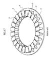
- each tooth 2 is composed of a plurality of steel plates 2a laminated in a radial direction thereof for a countermeasure to core loss, and a plurality of such teeth 2 are arranged and fixed side by side with a predetermined distance in the circumferential direction of a disc, i.e., substantially ring-shaped, stator yoke core 6. Coils are wound up around these teeth 2 through insulating material as bobbins, not shown. Further, as shown in Fig. 17, the teeth 2, the stator yoke core 6 and the coils are integrally fixed by means of molding resin 7 as shown in Fig. 16 such that surfaces 2b of the teeth 2 opposing to the rotor are exposed.
- the steel plates 2a of the teeth 2 are assembled to the stator yoke core 6 in a separated state and then molded and fixed together by means of molding resin 7.
- This publication shows salient-pole type core lamination plates corresponding to the steel plates of the teeth mentioned above, the core lamination plates being laminated and fixed by means of a hole formed to the respective plates.
- the holes are formed by punching process, and at the paragraph [0014], the punched-out plates are figured at a portion above the figure of a rolled steel plate in the respective pressing stage in Fig. 2. According to such description, it is apparent that the holes formed to the core lamination plates are through holes.
- these steel plates 2a are insulated by insulating films, such insulating films may be broken by the formation of the half pierce member, which may result in short-circuiting, and the respective steel plates 2a become electrically connected state. Accordingly, if such half pierce members are located at several portions, a closed circuit will be presented through these half pierce members, and a magnetic flux crosses this closed circuit and then the induction current passes, resulting in the cause of energy loss, thus being inconvenient and disadvantageous.
- the holes for fixing the respective core lamination plates corresponding to the steel plates of the teeth (tooth) are formed in the above prior art publication, but these holes are through holes, which are not for causing the induction current.
- the present invention was conceived in consideration of the above prior art, and an object of the present invention is to provide a rotary electric machine capable of minimally suppressing the induction current loss even if teeth are fixed through fitting portions and also to provide an electric wheelchair mounted with such rotary electric machine.
- a rotary electric machine comprising:
- the fitting portion is formed in an area apart from the head portion and the insert portion by not less than a 1/2 length of a width of the coil wind-up portion.
- the teeth and the magnets may be arranged so as to oppose to each other with a space in a rotation axis direction.
- the magnetic steel plates have both side surfaces on which insulating film is formed other than the fitting portion so that a closed circuit is formed between the magnetic steel plates through the fitting portions.
- the insulating film formed on the side surfaces of the magnetic steel plates is broken at the fitting portion when the fitting portions are formed and fitted to the steel plates.
- the fitting portions may be formed to the respective steel plates so as to have protruded portions and recessed portions such that the protruded portion of the fitting portion of one magnetic steel plate is fitted and fixed to the recessed portion of the fitting portion of an adjacent magnetic steel plate when the magnetic steel plates are laminated together.
- fitting portions are formed in parallel with or on the center line of the coil wind-up portion.
- fitting portions are each formed as a half pierce portion having a half protruded portion and half recessed portion or each formed as a V-shaped calking portion.
- a plurality of fitting portions formed to the coil wind-up portions, each having substantially the constant width, of the teeth are arranged along the center line of this wind-up portion. Therefore, at the time of high flux density in the coil wind-up portion, the magnetic flux flows in the same direction as that of the center line thereof, and by arranging the plural fitting portions in alignment with the same direction as that of the center line, the variation in the magnetic flux flowing the closed circuit formed between the fitting portions can be significantly suppressed, and hence, the loss of energy can be also reduced.
- the formation of the plural fitting portions can contribute to the assembling performance of the rotary electric machine with improved strength against conveyance, transportation or like.
- the fitting portions are formed at portions apart from the head portion or insert portion of the tooth by not less than 1/2 width of the wind-up portion thereof, the disturbance of the magnetic flux at the portions near the head portion, the stator yoke core or yoke insert portion can be significantly suppressed and the loss of energy can be also suppressed.
- the rotary electric machine formed according to the present invention has a compact, flat and lightweight structure with the small loss of energy can be provided.
- each of the fitting portions formed to the magnetic steel plates has protruded and recessed portions, and the protruded portion of one steel plate is fitted to the recessed portion of the other adjacent steel plate to thereby easily laminate and fix the respective steel plates together.
- an electric wheelchair comprising:
- the electric wheelchair mounted with the improved rotary electric machine having compact structure and high output performance can be provided.
- the first embodiment of the present invention is represented by Figs. 1 to 12.
- reference numeral 11 denotes an electric wheelchair or electrically powered wheelchair mounted with an electric motor 12 as a “rotary electric machine” according to the present invention, and the electric wheelchair is driven and traveled by the driving force of the electric motor 12.
- the electric wheelchair 11 is provided with a frame 13 as a framework of a vehicle (electric wheelchair body), a seat 14 on which a user sits and a pair of driving wheel units 15 in which the electric motors 12 are mounted.
- the paired driving wheel units 15 are driven so as to drive driven wheels 16 by predetermined amount (distance).
- the driven wheels 16 are operated independently, and by the operation of the operation unit 17, the driven wheels 16 are changed in their rotating directions and driven speed, respectively.
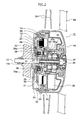
- the driving wheel unit 15 is composed, as unit, of the electric motor 12, the driving unit, the driven unit 16 and so on, and as shown in Fig. 2, the driving wheel unit 15 is fixed to the frame 13 by means of bolt 19 and nut 19a.
- the electric motor 12 is of an axial gap type composed of a stator 21 and a rotor 22, which are accommodated in a space defined by a case 23 and a cover 24.
- the bolt 19 is planted to the cover 24.
- the stator 21 is fastened to the case 23 by means of bolt 51, and on the other hand, the rotor 22 is fitted to a rotor shaft 30, through serration fitting, provided for the case 23 to be rotatable through bearings 27, 27 and fixed thereto.
- the rotor 22 has, as shown in Figs. 3 and 4, a disc shaped rotor yoke 33, which has a central portion fitted to the rotor shaft 30 through the serration fitting.
- a plurality of magnets 34 are arranged and bonded to be fixed to the peripheral edge portion of the rotor yoke 33 at a predetermined constant interval in the circumferential direction thereof. These magnets 34 are disposed so as to oppose to the stator 21 with a gap C (Fig. 2) in the rotation axis direction.
- These magnets 34 are arranged so that N and S poles are adjacently alternated and bonded and fixed to the rotor yoke 33 in the shape of circle.
- the rotor yoke 33 is press worked as shown in Figs. 2 and 3 so as to provide a central recessed shape 33a, and in this recessed portion 33a, an electromagnetic brake 36 fixed to the cover 24 is accommodated.
- An annular rotary body 36a and the rotor 22, of which rotations are stopped by the electromagnetic brake 36, are made stationary in the rotating direction through a pin 37.
- a sensor magnet 38 is bonded and fixed to the opposite side of the recessed portion 33a, and a pole position sensor (hole IC) 40 opposing to the sensor magnet 38 is fixed to the case 23.
- the pole position sensor 40 is electrically connected to a controller 39, and the pole position of the rotor 22 is detected by the pole position sensor 40.
- a sun-gear 30a is mounted to the rotor shaft 30 so as to be meshed with a two-staged planetary gear 42a of a planetary reduction gear 42.
- the planetary reduction gear 42 reduces the rotation of the rotor 22, which is then transmitted to a hub 44, and the rotation of the hub 44 rotates the driving wheel 16.
- the stator 21 is provided with a substantially disc (ring) shaped stator yoke core 47, a plurality of teeth 48 arranged in the circumferential direction of the stator yoke core 47 with a predetermined interval and a coil 50 wound up around each of the teeth (i.e., tooth) 48 through bobbins 49.
- These stator yoke core 47, the teeth 48 and the coils 50 are integrally molded and fixed together.
- a plurality of collars 53 are inserted around the stator 21 to thereby simultaneously form mount flanges 52a.
- the coil 50 is coupled with each of U, V and W-phases, and one end of each coupling coil is electrically connected (neutral point) and the other end thereof is derived out of the mold so as to be connected to a driver.
- stator yoke core 47 is formed from a plurality of steel plates 54, having the same shape, which are laminated as shown in Fig. 8, and formed with fitting holes 47a into which teeth 48 are inserted.
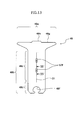
- the tooth 48 is formed by laminating a plurality of magnetic steel plates 57 so as to provide a T-shape, and is composed of a wider head portion 48a, which is opposed to the magnet 34 of the T-shaped tooth 48, and a leg portion 48b thereof.
- the leg portion 48b includes a coil wind-up portion 48c having a constant width around which the coil 50 is wound up and an insert portion 48d to be inserted into the fitting hole 47a of the stator yoke core 47.
- the wind-up portion 48c is formed with a plurality of half pierce portions 57a (two portions in the illustration) as fitting portions for fixing a plurality of laminated magnetic steel plates 57. Further, the half pierce portion 57a is in the form of half blind hole shape (having concave-convex portion), so that this portion is called as "half pierce portion" 57a herein.
- the half pierce portions 57a are arranged in the direction parallel with the center line O1 of the wind-up portion 48c, and in the illustration, they are arranged on the center line O1 which is substantially parallel to the longitudinal direction of T-shaped tooth (or vertical direction in Fig. 9).
- These two half pierce portions 57a is positioned in an area A apart from the head portion 48a and the insert portion 48d by 1/2 distance of the width W of the wind-up portion 48c as shown in the hatched portion of Fig. 11.
- each of the half pierce portions 57a of one magnetic steel plate 57 has a substantially rectangular, in section, protruded portion 57b which is fitted into a recessed portion 57c of the half pierce portion 57a of the adjacent one magnetic steel plate 57.
- the magnetic steel plate 57 is coated, at its both side surfaces, with an insulating film 57d entirely to be insulated.
- the side surface portion 57e of the fitting protruded portion 57b and the side surface portion 57f of the fitted recessed portion 57c are not coated with the insulating film because of the formation of the half pierced portion 57a, so that the adjacent magnetic steel plates 57 are electrically short-circuited as shown with arrows in Fig. 10, thus constituting a closed circuit.
- the insert portion 48d of the tooth 48 is formed with a resin filling groove 48f in which a molding resin 52 is filled up so as to prevent the tooth 48 from coming off.
- the head portion 48a thereof is also formed with an opposing surface 48g opposing to the magnet 34 of the rotor 22, and a protruded portion 48h is formed to the opposing surface 48g at substantially a central portion in the stator circumferential direction so as to extend radially.
- the protruded portion 48h has the same height and width in the entire length direction thereof.
- the opposing side surfaces 48g except the protruded portion 48h are embedded with the molding resin 52 as shown in Fig. 5.
- the opposing surface 48g of the tooth 48 and the magnet 34 of the rotor 22 are arranged so as to oppose to each other through a gap C in the rotation axis direction.
- reference numeral 59 denotes a spork of the wheel and 60 denotes a hand rim.
- the first embodiment will be operated in the manner mentioned hereunder.
- the magnetic flux flows through the rotor yoke 33, the magnet 34, the teeth 48 and the stator yoke core 47, and the magnetic flux flows in parallel with the center line O1 (see Fig. 11) at the wind-up portion 48c of the tooth leg portion, but the flux flow directions in other portions such as head portion 48a and the insert portion 48d are not constant.
- the closed circuit constituted by the structure of the half pierce portions 57a is also formed along the center line O1, whereby the change in the magnetic flux flowing across the closed circuit can be reduced, and as a result, the induction current passing the closed circuit is also reduced to thereby suppress the energy loss.
- Fig. 12A shows the magnetic flux flow in an arrangement in which the center line O1 of the wind-up portion 48c and a center line 02 of the magnet 34 are coincident with each other
- Fig. 12B shows the magnetic flux flow in an arrangement in which the center lines O1 and O2 are not coincident and slightly shifted from each other.
- the flow of the magnetic flux is disturbed at the portion near the head portion 48a and the insert portion 48d, by providing the two half pierce portions 57a in the hatched area A apart from the head portion 48a and the insert portion 48d by the distance of not less than 1/2 width of the wind-up portion 48c as shown in Fig. 11, the magnetic flux flows along the center line O1 in this area A, so that the generation of the induction current can be further suppressed, thus reducing the energy loss.
- the tooth 48 shown in Fig. 8 is formed by laminating a plurality of magnetic steel plates 57 of the same kind, working cost and molding cost can be suppressed minimally, and in addition, these magnetic steel plates 57 are caulked and fixed by the half pierce portions 57a, so that these steel plates can be easily laminated and assembled as the tooth.
- the teeth 48 are formed with the resin filling grooves 48f each having a wide inner space in which the molding resin 52 is filled up, so that the teeth 48 can be firmly fixed to the stator yoke core 47 to thereby preventing then from coming off.
- the coming-off prevention structure against the attractive force of the magnet 34 can be also formed by covering, with the molding resin 52, portions other than the protruded portion 48h of the opposing surface 48g of the tooth 48.
- the energy loss can be suppressed minimally, so that an electric wheelchair 11 provided with such electric motor 12 can be also preferably provided.
- Figs. 13 and 14 represent the second embodiment of the present invention.
- the structure of the fitting portion differs from that of the first embodiment.
- the half pierce portion 57a has substantially the circular shape as a front view, but in this second embodiment, this portion has a rectangular shape in the direction along the center line O1 of the wind-up portion 48c as shown in Fig. 13, and the respective magnetic plates 57 are caulked and fixed together by V-shaped caulking portions 57f each showing V-shape as shown in Fig. 14 in cross-section.
- V-shaped caulking portions 57f each showing V-shape as shown in Fig. 14 in cross-section.
- These two caulking portions 57f are arranged along or on the center line O1 of the wind-up portion 48c as like as the half pierce portions 57a of the first embodiment.
- the "fixing portion” such as half pierce portions in the first embodiment or V-shaped caulking portions in the second embodiment are formed simultaneously in the pressing process of the steel plates 57, and in the subsequent process, when the plural steel plates are laminated and pressed, the "fitting portions" are fitted and fixed together.
- the present invention is not limited to the described lamination method.
- fitting portions is also not limited to the described embodiment and many other changes may be made as far as the steel plates can be laminated and fixed together.
- two half pierce portions or calking portions are formed, three or more ones may be formed or a plurality of rows of them may be also formed along the center line.
- the portion of the tooth 48 other than the protruded portions 48h of the opposing surface 48a of the tooth is covered by the molding resin 52, these portions may be partially covered by the molding resin as shown in Fig. 15.
Landscapes
- Engineering & Computer Science (AREA)
- Power Engineering (AREA)
- Health & Medical Sciences (AREA)
- Life Sciences & Earth Sciences (AREA)
- Animal Behavior & Ethology (AREA)
- General Health & Medical Sciences (AREA)
- Public Health (AREA)
- Veterinary Medicine (AREA)
- Transportation (AREA)
- Mechanical Engineering (AREA)
- Iron Core Of Rotating Electric Machines (AREA)
- Connection Of Motors, Electrical Generators, Mechanical Devices, And The Like (AREA)
Applications Claiming Priority (1)
| Application Number | Priority Date | Filing Date | Title |
|---|---|---|---|
| JP2005210497A JP4993883B2 (ja) | 2005-07-20 | 2005-07-20 | 回転電機及び電動車椅子 |
Publications (2)
| Publication Number | Publication Date |
|---|---|
| EP1746703A2 true EP1746703A2 (fr) | 2007-01-24 |
| EP1746703A3 EP1746703A3 (fr) | 2015-01-21 |
Family
ID=37075634
Family Applications (1)
| Application Number | Title | Priority Date | Filing Date |
|---|---|---|---|
| EP06014617.2A Withdrawn EP1746703A3 (fr) | 2005-07-20 | 2006-07-13 | Machine électrique tournante et fauteuil roulant électrique équipé d'une machine électrique tournante |
Country Status (4)
| Country | Link |
|---|---|
| US (1) | US7528521B2 (fr) |
| EP (1) | EP1746703A3 (fr) |
| JP (1) | JP4993883B2 (fr) |
| CN (1) | CN100541974C (fr) |
Cited By (4)
| Publication number | Priority date | Publication date | Assignee | Title |
|---|---|---|---|---|
| US7528521B2 (en) * | 2005-07-20 | 2009-05-05 | Yamaha Hatsudoki Kabushiki Kaisha | Rotary electric machine and electric wheelchair mounted with rotary electric machine |
| US7592733B2 (en) | 2005-07-20 | 2009-09-22 | Yamaha Hatsudoki Kabushiki Kaisha | Rotary electric machine and electric wheelchair mounted with rotary electric machine |
| US7642686B2 (en) | 2005-07-20 | 2010-01-05 | Yamaha Hatsudoki Kabushiki Kaisha | Rotary electric machine and electric wheelchair mounted with rotary electric machine |
| CN118907972A (zh) * | 2024-10-10 | 2024-11-08 | 天津大桥金属焊丝有限公司 | 一种埋弧焊丝生产用收卷装置 |
Families Citing this family (32)
| Publication number | Priority date | Publication date | Assignee | Title |
|---|---|---|---|---|
| JP5019967B2 (ja) * | 2007-06-20 | 2012-09-05 | パナソニック株式会社 | モータ用の積層コアとこれを用いるモータ |
| WO2009057674A1 (fr) * | 2007-11-01 | 2009-05-07 | Daikin Industries, Ltd. | Noyau magnétique pour induit, procédé de fabrication de celui-ci, induit, machine électrique tournante et compresseur |
| JP5365109B2 (ja) * | 2007-11-15 | 2013-12-11 | ダイキン工業株式会社 | ティース、電機子用磁芯 |
| EP2061136A1 (fr) * | 2007-11-19 | 2009-05-20 | Siemens Aktiengesellschaft | Engrenage direct électrique pour un cylindre |
| JP2010017072A (ja) | 2008-06-06 | 2010-01-21 | Daikin Ind Ltd | 電機子コア、電機子、電機子コアの製造方法及び電機子の製造方法 |
| JP5256007B2 (ja) * | 2008-12-02 | 2013-08-07 | アスモ株式会社 | 電機子並びにアキシャルギャップ型回転電機 |
| JP4710993B2 (ja) | 2009-02-26 | 2011-06-29 | ダイキン工業株式会社 | 電機子用コア |
| US8496080B2 (en) | 2010-09-30 | 2013-07-30 | National Taiwan University | Wheel driven mechanism |
| JP5266355B2 (ja) * | 2011-03-30 | 2013-08-21 | パナソニック株式会社 | モータおよびポンプならびにポンプ駆動機器 |
| ES2901153T3 (es) | 2011-07-06 | 2022-03-21 | Max Mobility Llc | Sistema de asistencia de accionamiento energético basado en el movimiento para sillas de ruedas |
| JP6126479B2 (ja) * | 2012-09-14 | 2017-05-10 | ヤマハ発動機株式会社 | 車椅子用車輪、車椅子 |
| US20140175931A1 (en) * | 2012-12-21 | 2014-06-26 | Samsung Electro-Mechanics Co., Ltd. | Axial flux permanent magnet motor |
| US9144525B2 (en) * | 2013-03-14 | 2015-09-29 | Max Mobility, Llc. | Motion assistance system for wheelchairs |
| US20150091410A1 (en) * | 2013-10-02 | 2015-04-02 | Regal Beloit Australia Pty Ltd. | Axial flux electrical machines and methods of manufacturing the same. |
| CN106415992B (zh) * | 2014-06-09 | 2019-02-05 | 株式会社安川电机 | 旋转电机、旋转电机的控制装置、旋转电机的控制方法 |
| US9795524B2 (en) | 2015-02-24 | 2017-10-24 | Max Mobility, Llc | Assistive driving system for a wheelchair |
| US11394252B2 (en) | 2017-10-24 | 2022-07-19 | Stryker Corporation | Power transfer system with patient support apparatus and power transfer device to transfer power to the patient support apparatus |
| US11139666B2 (en) | 2017-10-24 | 2021-10-05 | Stryker Corporation | Energy harvesting and propulsion assistance techniques for a patient support apparatus |
| US10797524B2 (en) | 2017-10-24 | 2020-10-06 | Stryker Corporation | Techniques for power transfer through wheels of a patient support apparatus |
| US10910888B2 (en) | 2017-10-24 | 2021-02-02 | Stryker Corporation | Power transfer system with patient transport apparatus and power transfer device to transfer power to the patient transport apparatus |
| US11389357B2 (en) | 2017-10-24 | 2022-07-19 | Stryker Corporation | Energy storage device management for a patient support apparatus |
| US10167051B1 (en) | 2017-12-12 | 2019-01-01 | Max Mobility, Llc | Assistive driving system for a wheelchair and method for controlling assistive driving system |
| WO2019142290A1 (fr) * | 2018-01-18 | 2019-07-25 | 三菱電機株式会社 | Stator, moteur, ventilateur, aspirateur électrique et sèche-mains |
| US10916976B2 (en) * | 2018-08-24 | 2021-02-09 | Regal Beloit America, Inc. | Axial flux electric machine and methods of assembling the same |
| JP7153403B2 (ja) * | 2018-08-31 | 2022-10-14 | チェジャン パングット パワー テクノロジー カンパニー リミテッド | セグメントコア及びディスクモータ |
| TWI676472B (zh) * | 2018-10-05 | 2019-11-11 | 財團法人工業技術研究院 | 助力輪 |
| WO2020088488A1 (fr) | 2018-10-31 | 2020-05-07 | 淮安威灵电机制造有限公司 | Moteur à flux transversal |
| CN112889202A (zh) * | 2018-12-18 | 2021-06-01 | 住友电气工业株式会社 | 铁芯、定子及旋转电机 |
| FR3100399B1 (fr) * | 2019-08-27 | 2021-09-24 | Moving Magnet Tech | Machine à bobinage toroïdal |
| JP2021141746A (ja) * | 2020-03-06 | 2021-09-16 | セイコーエプソン株式会社 | アキシャルギャップモーター |
| CN115398777A (zh) * | 2020-05-08 | 2022-11-25 | 住友电气工业株式会社 | 铁芯片、定子铁芯、定子、旋转电机及铁芯片的制造方法 |
| DE102021108957A1 (de) | 2021-04-10 | 2022-10-13 | Schaeffler Technologies AG & Co. KG | Elektrische Maschine |
Citations (1)
| Publication number | Priority date | Publication date | Assignee | Title |
|---|---|---|---|---|
| JPH11318059A (ja) | 1998-05-01 | 1999-11-16 | Harmonic Drive Syst Ind Co Ltd | モータステータの積層鉄心の製造方法 |
Family Cites Families (42)
| Publication number | Priority date | Publication date | Assignee | Title |
|---|---|---|---|---|
| US4551645A (en) | 1981-06-04 | 1985-11-05 | Fuji Photo Film Co., Ltd. | Disc type brushless motor |
| JPS60152240A (ja) | 1984-01-18 | 1985-08-10 | Sankyo Seiki Mfg Co Ltd | 回転電機 |
| DE3574311D1 (en) | 1984-09-29 | 1989-12-21 | Toshiba Kk | Armature annular core |
| DE3700774C2 (de) | 1986-01-13 | 1998-11-12 | Papst Motoren Gmbh & Co Kg | Kollektorlose Gleichstrommaschine |
| US5234066A (en) | 1990-11-13 | 1993-08-10 | Staodyn, Inc. | Power-assisted wheelchair |
| US5142178A (en) | 1991-04-12 | 1992-08-25 | Emerson Electric Co. | Apparatus for aligning stacked laminations of a dynamoelectric machine |
| US5489811A (en) * | 1992-06-11 | 1996-02-06 | Generac Corporation | Permanent magnet alternator |
| JP2932883B2 (ja) * | 1993-02-22 | 1999-08-09 | 三菱電機株式会社 | 電動機用ステータ鉄心および電動機用ステータ鉄心の製造方法 |
| JP2764236B2 (ja) * | 1993-03-24 | 1998-06-11 | 株式会社三井ハイテック | 積層鉄心の製造方法及び装置 |
| JP3171304B2 (ja) * | 1995-01-26 | 2001-05-28 | 株式会社三井ハイテック | 回転電機用固定子の製造方法 |
| JPH09131004A (ja) * | 1995-10-30 | 1997-05-16 | Asmo Co Ltd | 電気機器用鉄心素板及び鉄心 |
| JP3703554B2 (ja) | 1996-02-14 | 2005-10-05 | ヤマハ発動機株式会社 | 補助動力付き車椅子 |
| JPH10126982A (ja) | 1996-10-24 | 1998-05-15 | Matsushita Electric Ind Co Ltd | 永久磁石モータ |
| JPH10322944A (ja) | 1997-05-19 | 1998-12-04 | Minebea Co Ltd | モータ構造及びその製造方法 |
| JPH1118326A (ja) | 1997-06-18 | 1999-01-22 | Yaskawa Electric Corp | 永久磁石形電動機 |
| JPH11113195A (ja) * | 1997-10-01 | 1999-04-23 | Denyo Co Ltd | 電機子鉄心片の積層構造 |
| JP3460938B2 (ja) | 1997-11-10 | 2003-10-27 | ミネベア株式会社 | ブラシレスdcモータ構造 |
| DE19757136A1 (de) * | 1997-12-20 | 1999-06-24 | Temic Auto Electr Motors Gmbh | Bürstenloser, elektrisch kommutierter Motor |
| US6445105B1 (en) | 1999-04-06 | 2002-09-03 | General Electric Company | Axial flux machine and method of fabrication |
| NL1011876C2 (nl) | 1999-04-23 | 2000-10-24 | Aerpac Holding B V | Generator. |
| US6278217B1 (en) | 1999-12-09 | 2001-08-21 | General Electric Company | High voltage generator stator with radially inserted cable windings and assembly method |
| JP2000334001A (ja) * | 2000-01-01 | 2000-12-05 | Yamaha Motor Co Ltd | 電動式車椅子 |
| IT1320322B1 (it) | 2000-04-28 | 2003-11-26 | Filippis Pietro De | Motore brushless a magneti permanenti. |
| JP2002262496A (ja) * | 2001-03-05 | 2002-09-13 | Hitachi Ltd | 回転電機のコア構造 |
| TW553555U (en) * | 2001-09-26 | 2003-09-11 | Jia-Hau Fan | Modular stator structure |
| US6717324B2 (en) | 2001-10-15 | 2004-04-06 | Ming Yan Chen | Magnet motor device |
| CN1285154C (zh) | 2001-11-29 | 2006-11-15 | 雅马哈发动机株式会社 | 轴隙式旋转电机 |
| KR100678983B1 (ko) | 2001-11-29 | 2007-02-06 | 야마하하쓰도키 가부시키가이샤 | 축방향 간극형 회전전기기기 및 그 회전전기기기를 이용하는 전동이륜차 |
| JP3749490B2 (ja) * | 2002-01-28 | 2006-03-01 | 三菱電機株式会社 | 積層鉄心およびその製造方法 |
| JP4003058B2 (ja) | 2002-07-17 | 2007-11-07 | 株式会社富士通ゼネラル | 誘導電動機 |
| US20060103263A1 (en) | 2002-08-16 | 2006-05-18 | Shinya Naito | Rotating electric machine |
| JP2004080944A (ja) | 2002-08-20 | 2004-03-11 | Toyota Motor Corp | 電動機用ステータコア |
| AU2003264970A1 (en) | 2002-09-27 | 2004-04-19 | Yun-Hyun Cho | A flat board type brushless dc motor |
| JP2004194497A (ja) * | 2002-11-29 | 2004-07-08 | Denso Corp | 回転電機の組み合わせ固定子コア |
| JP2004236386A (ja) * | 2003-01-28 | 2004-08-19 | Suzuki Motor Corp | 電動車両の駆動装置 |
| JP3987027B2 (ja) | 2003-03-31 | 2007-10-03 | 三菱電機株式会社 | 回転電機の電機子 |
| US7271519B2 (en) * | 2003-10-02 | 2007-09-18 | Lg Electronics Inc. | Laminated body of motor and manufacturing method thereof |
| CN1627596A (zh) | 2003-12-12 | 2005-06-15 | 乐金电子(天津)电器有限公司 | 外齿型螺旋线定子铁芯 |
| US7262540B2 (en) * | 2004-02-26 | 2007-08-28 | Lg Electronics Inc. | Stator of outer rotor type motor for drum type washing machine |
| JP4712465B2 (ja) * | 2005-07-20 | 2011-06-29 | ヤマハ発動機株式会社 | 回転電機及び電動車椅子 |
| JP4993883B2 (ja) * | 2005-07-20 | 2012-08-08 | ヤマハ発動機株式会社 | 回転電機及び電動車椅子 |
| JP4726564B2 (ja) * | 2005-07-20 | 2011-07-20 | ヤマハ発動機株式会社 | 回転電機及び電動車椅子 |
-
2005
- 2005-07-20 JP JP2005210497A patent/JP4993883B2/ja not_active Expired - Fee Related
-
2006
- 2006-07-13 EP EP06014617.2A patent/EP1746703A3/fr not_active Withdrawn
- 2006-07-18 CN CNB2006101033332A patent/CN100541974C/zh not_active Expired - Fee Related
- 2006-07-19 US US11/488,976 patent/US7528521B2/en not_active Expired - Fee Related
Patent Citations (1)
| Publication number | Priority date | Publication date | Assignee | Title |
|---|---|---|---|---|
| JPH11318059A (ja) | 1998-05-01 | 1999-11-16 | Harmonic Drive Syst Ind Co Ltd | モータステータの積層鉄心の製造方法 |
Cited By (4)
| Publication number | Priority date | Publication date | Assignee | Title |
|---|---|---|---|---|
| US7528521B2 (en) * | 2005-07-20 | 2009-05-05 | Yamaha Hatsudoki Kabushiki Kaisha | Rotary electric machine and electric wheelchair mounted with rotary electric machine |
| US7592733B2 (en) | 2005-07-20 | 2009-09-22 | Yamaha Hatsudoki Kabushiki Kaisha | Rotary electric machine and electric wheelchair mounted with rotary electric machine |
| US7642686B2 (en) | 2005-07-20 | 2010-01-05 | Yamaha Hatsudoki Kabushiki Kaisha | Rotary electric machine and electric wheelchair mounted with rotary electric machine |
| CN118907972A (zh) * | 2024-10-10 | 2024-11-08 | 天津大桥金属焊丝有限公司 | 一种埋弧焊丝生产用收卷装置 |
Also Published As
| Publication number | Publication date |
|---|---|
| US7528521B2 (en) | 2009-05-05 |
| JP2007028854A (ja) | 2007-02-01 |
| CN100541974C (zh) | 2009-09-16 |
| CN1901323A (zh) | 2007-01-24 |
| JP4993883B2 (ja) | 2012-08-08 |
| US20070020985A1 (en) | 2007-01-25 |
| EP1746703A3 (fr) | 2015-01-21 |
Similar Documents
| Publication | Publication Date | Title |
|---|---|---|
| US7528521B2 (en) | Rotary electric machine and electric wheelchair mounted with rotary electric machine | |
| US7642686B2 (en) | Rotary electric machine and electric wheelchair mounted with rotary electric machine | |
| EP1746705B1 (fr) | Machine électrique tournante et fauteuil roulant électrique comprenant une machine électrique tournante | |
| US6483221B1 (en) | Electric motor | |
| EP1359661B1 (fr) | Moteur sans balai et dispositif pour direction assistée électrique équipé d'un tel moteur | |
| JP4529500B2 (ja) | アキシャルギャップ回転電機 | |
| JP4729551B2 (ja) | アキシャルギャップ型モータ | |
| JP5959747B2 (ja) | 固定子鉄心、固定子、回転電機、電動パワーステアリング装置、固定子の製造方法、回転電機の製造方法、電動パワーステアリング装置の製造方法 | |
| JP3716808B2 (ja) | 回転電機 | |
| JP2001275325A (ja) | 電動パワーステアリング装置 | |
| JP2000125525A (ja) | 車両用駆動装置 | |
| JP4720278B2 (ja) | アキシャルエアギャップ型電動機 | |
| JP2010183648A (ja) | 永久磁石回転電機及びそれを用いた電動車両 | |
| JP4211200B2 (ja) | 磁石併用同期機 | |
| KR100624817B1 (ko) | 스포크 타입 전동기의 로터 및 그 제조방법 | |
| CN114868322A (zh) | 电动机及具有该电动机的车辆用动力装置、发电机及具有该发电机的带有发电机的车轮用轴承 | |
| JP5691451B2 (ja) | 回転電機用ロータ | |
| EP3945658B1 (fr) | Moteur polyphasé, procédé de fabrication et appareil de cuisine | |
| JPH08116632A (ja) | 回転電機の固定子 | |
| JP2001224143A (ja) | アウタロータ型モータのステータ | |
| JP2006325295A (ja) | ステータ | |
| JP2010110163A (ja) | アキシャルギャップ型モータ及びそのロータ製造方法 | |
| EP1536544A2 (fr) | Moteur de traction avec rotor de frein à disque | |
| JP4911637B2 (ja) | アキシャルギャップ型モータ | |
| JP2012182947A (ja) | 回転電機 |
Legal Events
| Date | Code | Title | Description |
|---|---|---|---|
| PUAI | Public reference made under article 153(3) epc to a published international application that has entered the european phase |
Free format text: ORIGINAL CODE: 0009012 |
|
| AK | Designated contracting states |
Kind code of ref document: A2 Designated state(s): AT BE BG CH CY CZ DE DK EE ES FI FR GB GR HU IE IS IT LI LT LU LV MC NL PL PT RO SE SI SK TR |
|
| AX | Request for extension of the european patent |
Extension state: AL BA HR MK YU |
|
| 17P | Request for examination filed |
Effective date: 20070704 |
|
| PUAL | Search report despatched |
Free format text: ORIGINAL CODE: 0009013 |
|
| AK | Designated contracting states |
Kind code of ref document: A3 Designated state(s): AT BE BG CH CY CZ DE DK EE ES FI FR GB GR HU IE IS IT LI LT LU LV MC NL PL PT RO SE SI SK TR |
|
| AX | Request for extension of the european patent |
Extension state: AL BA HR MK RS |
|
| RIC1 | Information provided on ipc code assigned before grant |
Ipc: H02K 1/14 20060101AFI20141217BHEP Ipc: B60L 15/20 20060101ALI20141217BHEP Ipc: A61G 5/10 20060101ALI20141217BHEP Ipc: A61G 5/04 20130101ALI20141217BHEP Ipc: H02K 1/27 20060101ALI20141217BHEP Ipc: H02K 7/14 20060101ALI20141217BHEP |
|
| AKX | Designation fees paid |
Designated state(s): DE FR GB IT |
|
| AXX | Extension fees paid |
Extension state: AL Extension state: RS Extension state: MK Extension state: HR Extension state: BA |
|
| 17Q | First examination report despatched |
Effective date: 20160919 |
|
| STAA | Information on the status of an ep patent application or granted ep patent |
Free format text: STATUS: THE APPLICATION IS DEEMED TO BE WITHDRAWN |
|
| 18D | Application deemed to be withdrawn |
Effective date: 20170131 |