EP1747568B1 - Gleichstrom-energieversorgungs- und -verteilungsanlage für schiffe - Google Patents
Gleichstrom-energieversorgungs- und -verteilungsanlage für schiffe Download PDFInfo
- Publication number
- EP1747568B1 EP1747568B1 EP05752721A EP05752721A EP1747568B1 EP 1747568 B1 EP1747568 B1 EP 1747568B1 EP 05752721 A EP05752721 A EP 05752721A EP 05752721 A EP05752721 A EP 05752721A EP 1747568 B1 EP1747568 B1 EP 1747568B1
- Authority
- EP
- European Patent Office
- Prior art keywords
- pole
- poles
- power supply
- circuit breaker
- distribution installation
- Prior art date
- Legal status (The legal status is an assumption and is not a legal conclusion. Google has not performed a legal analysis and makes no representation as to the accuracy of the status listed.)
- Expired - Lifetime
Links
- 238000009434 installation Methods 0.000 title claims abstract 13
- 239000000446 fuel Substances 0.000 claims abstract description 4
- 239000004020 conductor Substances 0.000 claims description 23
- 239000000463 material Substances 0.000 claims description 10
- 230000001681 protective effect Effects 0.000 claims description 7
- RYGMFSIKBFXOCR-UHFFFAOYSA-N Copper Chemical compound [Cu] RYGMFSIKBFXOCR-UHFFFAOYSA-N 0.000 claims description 2
- 229910052802 copper Inorganic materials 0.000 claims description 2
- 239000010949 copper Substances 0.000 claims description 2
- 210000000056 organ Anatomy 0.000 abstract description 3
- 238000010791 quenching Methods 0.000 description 3
- 230000000171 quenching effect Effects 0.000 description 3
- 230000008878 coupling Effects 0.000 description 2
- 238000010168 coupling process Methods 0.000 description 2
- 238000005859 coupling reaction Methods 0.000 description 2
- 239000000696 magnetic material Substances 0.000 description 2
- XAGFODPZIPBFFR-UHFFFAOYSA-N aluminium Chemical compound [Al] XAGFODPZIPBFFR-UHFFFAOYSA-N 0.000 description 1
- 229910052782 aluminium Inorganic materials 0.000 description 1
- 239000011810 insulating material Substances 0.000 description 1
- 239000012212 insulator Substances 0.000 description 1
Images


Classifications
-
- H—ELECTRICITY
- H01—ELECTRIC ELEMENTS
- H01H—ELECTRIC SWITCHES; RELAYS; SELECTORS; EMERGENCY PROTECTIVE DEVICES
- H01H33/00—High-tension or heavy-current switches with arc-extinguishing or arc-preventing means
- H01H33/02—Details
- H01H33/59—Circuit arrangements not adapted to a particular application of the switch and not otherwise provided for, e.g. for ensuring operation of the switch at a predetermined point in the AC cycle
- H01H33/596—Circuit arrangements not adapted to a particular application of the switch and not otherwise provided for, e.g. for ensuring operation of the switch at a predetermined point in the AC cycle for interrupting DC
Definitions
- the invention relates to a DC power supply and distribution system for ships according to the preamble of patent claim 1; Such a system is for example by the WO 02/15361 A1 known.
- Ship power supply and distribution systems are, especially in underwater vessels, usually designed as a DC low-voltage networks with high operating voltages and potentials up to DC 1200 V. They have at least one, in some cases also several energy producers, such as e.g. Generators, batteries, possibly fuel cells, on the various consumers such. Supply traction motors or a vehicle electrical system for supplying auxiliary drives with energy.
- the energy producers and the energy consumers are connected to each other via protective and switching devices, on the one hand an operational switching on or off (eg for setting different driving circuits) of individual energy consumers, individual energy producers or certain parts of the power supply and distribution system and on the other hand in case of failure, in particular in the event of a short circuit, a shutdown of individual energy consumers or energy producers to allow whole parts of the power supply and distribution system.
- protective and switching organs come e.g. two-pole circuit breaker used.
- the electrical currents flowing in such a system generate stray magnetic fields.
- the stray fields can have an influence on the electromagnetic compatibility, the safety and the operating behavior of the system. For example, electronic controls can be influenced and thus cause faulty circuits propelr. In the case of naval ships, the stray fields can increase the risk to ships, for example due to magnetic mines.
- the switch has for this purpose three switching units, each with two switching paths, wherein the switching units are arranged with their switching paths in a circle and in the circuit adjacent switching paths are each traversed in opposite directions by current.
- At least one of the protection and switching elements is designed as a three-pole circuit breaker, which is switchable with its three poles in the system so that magnetic stray fields generated by the currents flowing through the three poles, at least partially compensate each other, and wherein a pneumatic drive is provided for switching the three poles
- the invention is based on the consideration that a not insignificant proportion of the magnetic stray fields is generated by the switching and protective devices. Therefore, according to the invention, a three-pole circuit breaker is used as the switching and protective device.
- a pole of a circuit breaker usually has a contact or switching element with usually two switching pieces (a fixed and a movable contact piece) and in each case at least one conductor connection for each of the contact pieces.
- a contact or switching element with usually two switching pieces (a fixed and a movable contact piece) and in each case at least one conductor connection for each of the contact pieces.
- the movable contact pieces are moved by a common drive element via a common drive mechanism (eg drive shaft).
- Three-pole circuit breakers are commonly used in AC systems, but not in DC systems. Deviating from this, however, is now targeted to use in a DC system. This is based on the knowledge that with the help of three poles or three conductors better compensation of magnetic fields can be achieved than is possible with only two poles.
- a pneumatic drive is used instead of the normally used to move switching pieces of the three poles electro-motor drive.
- a compressed-air drive has considerably fewer magnetic parts and thus generates much lower stray magnetic fields.
- the at least partially mutually compensating the magnetic fields is technically and constructively realized in a simple manner in that the three poles are arranged spatially parallel to each other, wherein a second pole is arranged substantially centrally between a first and a third pole and wherein the first and the current flowing in the third pole is half the size of the current flowing through the second pole and directed counter to it.
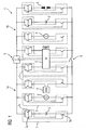
- An in FIG. 1 shown DC power supply and distribution system 1 of an underwater ship has a first sub-network 1a and a second sub-network 1b, which are interconnected via coupling points 9.
- the two sub-networks 1a, 1b have generators 2 and batteries 3 and a fuel cell system 4 for generating energy.
- the energy generated is used to power a motor 5 (eg DC motor or DC-powered motor) for driving the underwater vessel and a vehicle electrical system, not shown.
- a charging port 6 a battery charge by an external power source is possible.
- the motor 5 is in this case fed by both subnetworks 1a, 1b, so that the operation of the engine 5 and thus the maneuverability of the ship is ensured even if one of the two subnetworks 1a, 1b fails.
- each protective and switching elements circuit breaker 7 each with three poles 7a, 7b, 7c electrically connected.
- the three poles 7a, 7b, 7c are in this case connected in such a way that magnetic stray fields, which are generated by the currents flowing through the three poles, at least partially compensate each other
- the poles 7a and 7c of the circuit breaker 7 are in this case with their terminals 7.1 and 7.2 or 7.5 and 7.6 in parallel in a forward conductor L + a load L (eg the motor 5 of the system 1 of FIG. 1 ), while the pole 7b is connected with its terminals 7.3 and 7.4 in a return conductor L- of the load L.
- a load L eg the motor 5 of the system 1 of FIG. 1
- the three poles 7a, 7b, 7c of the circuit breaker 7 are arranged spatially parallel to each other, wherein the pole 7b is arranged substantially centrally between the pole 7a and the pole 7c.
- a compressed air drive 15 is provided, which is supplied via a compressed air connection 15a from a compressed air system of the underwater ship, not shown, with compressed air.
- the circuit breaker 7 is designed as a self-supporting bodybuilder without special base plate.
- Everyone who Pole 7a-c is arranged in each case consisting of insulating material housing 13 and has an arc chamber 8 with a number of approximately equally large quenching plates 11.
- the housings 13 of the three poles 7a-c are clamped together to form a fixed switch frame.
- the front end of the circuit breaker 7 forms a front panel 10.
- various shafts 12 eg one or more switching shafts, drive shafts and / or tripping shafts
- the pneumatic drive 15 for driving the drive mechanism is arranged on the front side of the front panel 10.
- each of the poles 7a-c has a switching element 18 each having a stationary contact piece 18a and a movable contact piece 18b.
- the compressed-air drive 15 acts on the movable contact pieces 18b via mechanical intermediate links (eg switching locks 16, shafts 12).
- each of the poles 7a-c has a magnetic overcurrent release 19.
- the stray magnetic fields can be further reduced if the power switch 7 at least partially made of non-magnetic materials. Since the waves due to comparatively large mass and volume cause magnetic stray fields in particular extent, preferably at least one of the shafts 12, in the best case all shafts 12, of an amagnetic material. The same applies to the front panel 10, which therefore preferably also consists of an amagnetic material.
- the quenching plates 11 as far as possible also consist of an amagnetic material.
- plates 11 made of an amagnetic material as far as possible, and only for the stability of the arc chamber
- Required sheets 11 are made of a magnetic and thus usually mechanically stronger material.
- at least 50% of the quenching plates consist of an amagnetic material, in particular of copper.
- the proportion of non-magnetic sheets is about 80%, the remaining 20% of magnetic material serve the stability of the arc chamber.
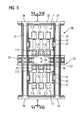
- a further reduction of the stray magnetic fields can be achieved by using the three-pole circuit breaker 7, as in FIGS. 5 to 7 is shown in a switchgear frame 20 with at least one bus bar 21 having a substantially tubular outer conductor 22 and a substantially coaxial therewith arranged inner conductor 23, wherein the first pole 7a and the third pole 7c with the inner conductor 23 and the second pole 7b are electrically connected to the outer conductor 22.
- a switching frame 20 with such a bus bar 21 is for example from the DE 200 08 566 U1 known.
- the outer conductors 22 and the inner conductor 23 are in this case e.g. fixed relative to each other by means of a screw / insulator system 24.
- the outer conductor 22 consist of two profile rails 22a, 22b with an open cross-section, in the illustrated embodiment with a U-shaped cross-section. These are connected by connectors 25 with a T-shaped cross section and fastened.
- a T-leg 29 protrudes from the rails and is used for fastening and contacting.
- inner conductor 23 has in places transversely to the longitudinal central axis projecting connecting pieces 26, the electrically insulated the slot between the two outer conductors forming profile rails 22a, 22b protrude and serve the contacting and attachment.
- the switching frame 20 consists of different bar-like (non-magnetic) extruded aluminum sections 31, 32, which are connected to one another by means of corner connectors 34.
- a first three-pole circuit breaker 7 is located above the bus bar 21, and a second three-pole circuit breaker 17 is disposed below the bus bar 21 in the switching tower 20.
- the circuit breakers 7,17 are mounted on mounting units 37, which in turn are secured by means of fastening pieces 42 to the extruded profiles 31.
- the terminals 7.2 and 7.6 of the switch 7 and the terminals 7.1 and 7.5 of the circuit breaker 17 are electrically connected to terminals 25 of the outer conductor 22, the terminal 7.4 of the circuit breaker 7 and the terminal 7.3 of the circuit breaker 17 are electrically connected to terminals 26 of the inner conductor 23.
- the remaining terminals of the circuit breakers 7, 17 are not shown in detail, e.g. electrically connected to system components via cable connections.
Landscapes
- Engineering & Computer Science (AREA)
- Power Engineering (AREA)
- Arc-Extinguishing Devices That Are Switches (AREA)
- Cable Transmission Systems, Equalization Of Radio And Reduction Of Echo (AREA)
- Direct Current Feeding And Distribution (AREA)
- Supply And Distribution Of Alternating Current (AREA)
Description
- Die Erfindung betrifft eine Gleichstrom-Energieversorgungs-und -verteilungsanlage für Schiffe gemäß Oberbegriff des Patentanspruchs 1; eine derartige Anlage ist z.B. durch die
WO 02/15361 A1 - Schiffs-Energieversorgungs- und -verteilungsanlagen sind, insbesondere in Unterwasserschiffen, meist als Gleichstrom-Niederspannungsnetze mit hohen Betriebsspannungen bzw. Potentialen bis DC 1200 V ausgebildet. Sie weisen zumindest einen, teilweise auch mehrere Energieerzeuger wie z.B. Generatoren, Batterien, ggf. Brennstoffzellen, auf, die verschiedene Verbraucher wie z.B. Fahrmotoren oder ein Bordnetz zur Speisung von Hilfsantrieben mit Energie versorgen. Die Energieerzeuger und die Energieverbraucher sind über Schutz- und Schaltorgane miteinander verbunden, die zum einen ein betriebliches Zu-oder Abschalten (z.B. zur Einstellung verschiedener Fahrschaltungen) einzelner Energieverbraucher, einzelner Energieerzeuger oder bestimmten Teilen der Energieversorgungs- und Verteilungsanlage und zum anderen im Fehlerfall, insbesondere im Fall eines Kurzschlusses, ein Abschalten einzelner Energieverbraucher oder Energieerzeuger bis hin zu ganzen Teilen der Energieversorgungs- und Verteilungsanlage ermöglichen sollen. Als Schutz- und Schaltorgane kommen z.B. zweipolige Leistungsschalter zum Einsatz.
- Die in einer solchen Anlage fließenden elektrischen Ströme erzeugen magnetische Streufelder. Je größer die Stromstärken sind, desto größer auch die Feldstärken dieser Streufelder. Die Streufelder können einen Einfluss auf die elektromagnetische Verträglichkeit, die Sicherheit und das Betriebsverhalten der Anlage haben. Beispielsweise können elektronische Steuerungen beeinflusst und somit Fehlschaltungen hervorgerufen werder. Bei Marineschiffinen kann durch die Streufelder die Gefährdung der Schiffe - beispielsweise durch Magnetminen - erhöht werden.
- Aus der
US-A-4 262 215 ist bereits ein dreipoliger Schalter bekannt, der mit seinen drei Polen derart in eine Anlage schaltbar ist, das sich die von den durch die drei Pole fließenden Ströme erzeugten magnetischen Streufelder zumindest teilweise gegenseitig kompensieren. Der Schalter weist hierzu drei Schalteinheiten mit jeweils zwei Schaltstrecken auf, wobei die Schalteinheiten mit ihren Schaltstrecken in einem Kreis angeordnet sind und in dem Kreis benachbarte Schaltstrecken jeweils gegensinnig von Strom durchflossen werden. - Es ist deshalb Aufgabe vorliegender Erfindung, eine Gleichstrom-Energieversorgungs- und -verteilungsanlage der eingangs erwähnten Art mit gegenüber dem Stand der Technik reduzierten magnetischen Streufeldern anzugeben.
- Die Lösung dieser Aufgabe gelingt dadurch, dass zumindest eines der Schutz- und Schaltorgane als dreipoliger Leistungsschalter ausgebildet ist, der mit seinen drei Polen derart in die Anlage schaltbar ist, dass sich magnetische Streufelder, die von den durch die drei Pole fließenden Ströme erzeugt werden, zumindest teilweise gegenseitig kompensieren, und wobei ein Druckluftantrieb zum Schalten der drei Pole vorgesehen ist
- Die Erfindung geht hierbei von der Überlegung aus, dass ein nicht unbedeutender Anteil der magnetischen Streufelder durch die Schalt- und Schutzorgane erzeugt wird. Erfindungsgemäß wird deshalb als Schalt- und Schutzorgan ein dreipoliger Leistungsschalter verwendet.
- Ein Pol eine Leistungsschalters weist in der Regel ein Kontakt- oder Schaltglied mit üblicherweise zwei Schaltstücken (einem festen und einem bewegbaren Schaltstück) und jeweils zumindest einen Leiteranschluss für jedes der Schaltstücke auf. Unter einem dreipoligen Leistungsschalter wird im Rahmen der Erfindung ein Leistungsschalter mit drei Polen verstanden, deren bewegbare Schaltstücke von einem gemeinsamen Antriebselement über eine gemeinsame Antriebsmechanik (z.B. Antriebswelle) bewegt werden.
- Dreipolige Leistungsschalter werden üblicherweise in Wechselstromanlagen, aber nicht in Gleichstromanlagen verwendet. Abweichend hiervon erfolgt nun allerdings gezielt der Einsatz in einer Gleichstromanlage. Dies beruht auf der Erkenntnis, dass mit Hilfe dreier Pole bzw. dreier Leiter eine bessere Kompensation von Magnetfeldern erzielbar ist, als dies mit nur zwei Polen möglich ist.
- Statt des normalerweise zur Bewegung von Schaltstücken der drei Pole verwendeten elektro-motorischen Antriebes wird ein Druckluftantrieb verwendet. Im Vergleich zu einem elektro-motorischen Antrieb weist ein Druckluftantrieb erheblich weniger magnetische Teile auf und erzeugt somit wesentlich geringere magnetische Streufelder. Zudem ist Druckluft auf Schiffen, insbesondere auf Unterwasserschiffen, bereits vorhanden und somit eine Druckluftversorgung einfach realisierbar.
- Die zumindest teilweise gegenseitig Kompensation der Magnetfelder wird technisch-konstruktiv auf einfache Weise dadurch realisiert, dass die drei Pole räumlich parallel zueinander angeordnet sind, wobei ein zweiter Pol im Wesentlichen mittig zwischen einem ersten und einem dritten Pol angeordnet ist und wobei der durch den ersten und den dritten Pol fließende Strom jeweils halb so groß wie der durch den zweiten Pol fließende Strom und zu diesem entgegengesetzt gerichtet ist.
- Diese Stromgrößen und -richtungen können dadurch auf einfache Weise eingestellt werden, dass der erste und dritte Pol in Parallelschaltung in einen Hinleiter einer elektrischen Last und der zweite Pol in einen Rückleiter dieser elektrischen Last geschaltet sind.
- Die Erfindung sowie weitere vorteilhafte Ausgestaltungen der Erfindung gemäß Merkmalen der Unteransprüche werden im Folgenden anhand von Ausführungsbeispielen in den Figuren näher erläutert. Darin sind für gleiche Elemente die gleichen Bezugszeichen verwendet. Es zeigen:
-
FIG 1 eine Prinzipschaltung einer Gleichstrom-Energieversorgungs- und -verteilungsanlage eines Unterwasserschiffes in vereinfachter Darstellung, -
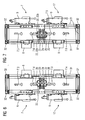
FIG 2 eine prinzipielle Beschaltung eines dreipoligen Leistungsschalters der Anlage vonFIG 1 , -
FIG 3 eine perspektivische Ansicht eines dreipoligen Leistungsschalters mit Druckluftantrieb, -
FIG 4 den prinzipiellen Aufbau eines dreipoligen SchaltersFIG 5 eine Rückansicht eines Schalttafelgerüstes mit einer Sammelschiene und zwei dreipoligen Leistungsschaltern, -
FIG 6 einen Schnitt entlang der Linie VI-VI gemäßFIG 4 , -
FIG 7 einen Schnitt entlang der Linie VII-VII gemäßFIG 4 . - Eine in
FIG 1 gezeigte Gleichstrom-Energieversorgungs- und -verteilungsanlage 1 eines Unterwasserschiffes weist ein erstes Teilnetz 1a und ein zweites Teilnetz 1b auf, die über Kupplungsstellen 9 miteinander verbunden sind. Die beiden Teilnetze 1a, 1b weisen zur Energieerzeugung Generatoren 2 und Batterien 3 sowie eine Brennstoffzellenanlage 4 auf. Die erzeugte Energie wird zur Speisung eines Motors 5 (z.B. DC-Motor oder DC-gespeister Motor) zum Antrieb des Unterwasserschiffes sowie eines nicht näher dargestellten Bordnetzes verwendet. Über einen Ladeanschluss 6 ist eine Batterieladung durch eine externe Energiequelle möglich. Der Motor 5 wird hierbei von beiden Teilnetzen 1a,1b gespeist, so dass der Betrieb des Motors 5 und damit die Manövrierfähigkeit des Schiffes auch bei Ausfall eines der beiden Teilnetze 1a,1b gewährleistet ist. - Zwischen die einzelnen Komponenten sowie an den Kupplungsstellen 9 sind als Schutz- und Schaltorgane Leistungsschalter 7 mit jeweils drei Polen 7a,7b,7c elektrisch geschaltet. Die drei Pole 7a,7b,7c sind hierbei derart in die Anlage geschaltet, dass sich magnetische Streufelder, die von den durch die drei Pole fließenden Ströme erzeugt werden, zumindest teilweise gegenseitig kompensieren
- Die Beschaltung der drei Pole 7a,7b,7c erfolgt hierbei gemäß
FIG 2 derart, dass durch den Pol 7b ein Strom Ib = I fließt, während durch die Pole 7a und 7c jeweils der halbe Strom Ia, b = 0.5 * .I fließt, wobei der durch die Pole 7a und 7c fließende Strom Ia bzw. Ic entgegengesetzt gerichtet ist zu dem Strom Ib durch den Pol 7b. - Die Pole 7a und 7c des Leistungsschalters 7 sind hierbei mit ihren Anschlüssen 7.1 und 7.2 bzw. 7.5 und 7.6 in Parallelschaltung in einen Hinleiter L+ einer Last L (z.B. den Motor 5 der Anlage 1 von
FIG 1 ) geschaltet, während der Pol 7b mit seinen Anschlüssen 7.3 und 7.4 in einen Rückleiter L- der Last L geschaltet ist. - Wie
FIG 3 zeigt, sind die drei Pole 7a,7b,7c des Leistungsschalters 7 räumlich parallel zueinander angeordnet, wobei der Pol 7b im Wesentlichen mittig zwischen dem Pol 7a und dem Pol 7c angeordnet ist. Zur Bewegung der nicht näher dargestellten Schaltstücke der Pole 7a-c ist ein Druckluftantrieb 15 vorgesehen, der über einen Druckluftanschluss 15a aus einer nichts näher dargestellten Druckluftanlage des Unterwasserschiffes mit Druckluft versorgt wird. - Durch die räumliche Anordnung der Pole 7a-c gemäß
FIG 3 und der Beschaltung gemäßFIG 2 werden bei Stromfluss durch den Schalter 7 die Magnetfelder, die durch den durch den Pol 7b fließenden Strom Ib = I erzeugt werden, weitgehend durch die Magnetfelder kompensiert, die durch Ströme Ia und Ib erzeugt werden, die durch die Pole 7a bzw. 7c fließen. Der Leistungsschalter 7 weist somit bei Stromfluss nur geringe magnetische Streufelder auf. Aufgrund des Druckluftantriebs wird dabei die Erzeugung magnetischer Streufelder durch den Antrieb des Leistungsschalters bei Schaltvorgängen des Leistungsschalters 7 vermieden. - Der Leistungsschalter 7 ist als ein selbsttragender Aufbauschalter ohne besondere Grundplatte ausgebildet. Jeder der Pole 7a-c ist in jeweils einem aus Isolierstoffwänden bestehenden Gehäuse 13 angeordnet und weist eine Lichtbogenkammer 8 mit einer Anzahl etwa gleich großer Löschbleche 11 auf. Die Gehäuse 13 der drei Pole 7a-c sind zu einem festen Schaltergerüst zusammengespannt. Den vorderen Abschluss des Leistungsschalters 7 bildet eine Frontplatte 10. In den Seitenwänden 14 des Schalters 7 sind verschiedene Wellen 12 (z.B. eine oder mehrere Schaltwellen, Antriebswellen und/oder Auslösewellen) der für alle Pole 7a-c gemeinsamen Antriebs-, Schalt- und Auslösemechanik gelagert. Der Druckluftantrieb 15 zum Antrieb der Antriebsmechanik ist auf der Vorderseite der Frontplatte 10 angeordnet.
- Der prinzipielle Aufbau des dreipoligen Leistungsschalters 7 ist in
FIG 4 dargestellt. Jeder der Pole 7a-c weist ein Schaltglied 18 mit jeweils einem feststehenden Schaltstück 18a und einem beweglichen Schaltstück 18b auf. Der Druckluftantrieb 15 wirkt über mechanische Zwischenglieder (z.B. Schaltschlösser 16 , Wellen 12) auf die beweglichen Schaltstücke 18b. Zusätzlich weist jeder der Pole 7a-c einen magnetischen Überstromauslöser 19 auf. - Die magnetischen Streufelder können noch weiter reduziert werden, wenn der Leistungsschalter 7 zumindest teilweise aus amagnetischen Materialen besteht. Da die Wellen aufgrund vergleichsweise großer Masse und Volumen in besonderem Maße magnetische Streufelder verursachen, besteht bevorzugt zumindest eine der Wellen 12, im besten Fall sämtliche Wellen 12, aus einem amagnetischen Material. Ähnliches gilt für die Frontplatte 10, die deshalb bevorzugt ebenfalls aus einem amagnetischen Material besteht.
- Wie sich herausgestellt hat, sollten bei hohen Anforderungen an die Amagnetik die Löschbleche 11 so weit möglich ebenfalls aus einem amagnetischen Material bestehen. So werden bevorzugt so weit möglich nur Bleche 11 aus einem amagnetischen Material verwendet, und nur für die Stabilität der Lichtbogenkammer erforderliche Bleche 11 sind aus einem magnetischen und somit in der Regel mechanisch festeren Material gefertigt sein. Vorteilhafterweise bestehen deshalb zumindest 50 % der Löschbleche aus einem amagnetischen Material, insbesondere aus Kupfer. Bevorzugt beträgt der Anteil der amagnetischen Bleche etwa 80 %, die verbleibenden 20% aus magnetischem Material dienen der Stabilität der Lichtbogenkammer.
- Eine weitere Reduzierung der magnetischen Streufelder kann dadurch erreicht werden, dass der dreipolige Leistungsschalter 7, wie in
FIG 5 - 7 dargestellt, in einem Schaltgerüst 20 mit zumindest einer Sammelschiene 21 mit einem im wesentlichen röhrenförmigen Außenleiter 22 und einem im wesentlichen koaxial zu diesem angeordneten Innenleiter 23 angeordnet ist, wobei der erste Pol 7a und der dritte Pol 7c mit dem Innenleiter 23 und der zweite Pol 7b mit dem Außenleiter 22 elektrisch verbunden sind. Hierdurch können magnetische Streufelder nicht nur im direkten Bereich der Leistungsschalter sondern auch im Bereich ihrer Stromzuführungen reduizert werden. Ein Schaltgerüst 20 mit einer solchen Sammelschiene 21 ist z.B. aus derDE 200 08 566 U1 bekannt. - Die Außenleiter 22 und der Innenleiter 23 sind hierbei z.B. mittels eines Schrauben-/Isolatorensystems 24 relativ zueinander fixiert. Die Außenleiter 22 bestehen aus zwei Profilschienen 22a, 22b mit offenem Querschnitt, im gezeigten Ausführungsbeispiel mit einem U-förmigen Querschnitt. Diese sind durch Anschlussstücke 25 mit einem T-förmigen Querschnitt verbunden und befestigbar. Ein T-Schenkel 29 ragt aus den Profilschienen heraus und dient der Befestigung und Kontaktierung.
- Der als Flachteil ausgebildete Innenleiter 23 hat stellenweise quer zu Längsmittelachse abstehende Anschlussstücke 26, die elektrisch isoliert den Schlitz zwischen den beiden den Außenleiter bildenden Profilschienen 22a, 22b durchragen und der Kontaktierung und Befestigung dienen.
- Das Schaltgerüst 20 besteht aus unterschiedlichen holmartigen (amagnetischen) Aluminium-Strangpressprofilen 31,32, die mittels Eckverbindern 34 miteinander verbunden sind.
- Ein erster dreipoliger Leistungsschalter 7 ist oberhalb der Sammelschiene 21 und ein zweiter dreipoliger Leistungsschalter 17 ist unterhalb der Sammelschiene 21 in dem Schaltgerüst 20 angeordnet. Die Leistungsschalter 7,17 sind auf Montageeinheiten 37 befestigt, die ihrerseits mittels Befestigungsstücken 42 an den Strangpressprofilen 31 befestigt sind. Die Anschlüsse 7.2 und 7.6 des Schalters 7 und die Anschlusstücke 7.1 und 7.5 des Leistungsschalters 17 sind mit Anschlussstücken 25 des Außenleiters 22, der Anschluss 7.4 des Leistungsschalters 7 und der Anschluss 7.3 des Leistungsschalters 17 sind mit Anschlussstücken 26 des Innenleiters 23 elektrisch verbunden. Die verbleibenden Anschlussstücke der Leistungsschalters 7, 17 sind in nicht näher dargestellter Weise z.B. über Kabelverbindungen elektrisch mit Anlagenkomponenten verbunden.
- Durch die Anordnung der Leistungsschalter 7 und 17 oberhalb bzw. unterhalb der Sammelschiene 21 in dem Schaltgerüst 20 ist eine weitere Reduzierung der Streufelder möglich, da sich die in den beiden Leistungsschaltern 7,17 erzeugten Magnetfelder teilweise gegenseitig kompensieren.
- Die Erfindung wurde zwar anhand einer Gleichstrom-Energieversorgungs- und -verteilungsanlage 1 eines Unterwasserschiffes erläutert, kann aber in entsprechend abgewandelter Form auch an Bord eines Überwasserschiffes, insbesondere eines Navy-Überwasserschiffes, Anwendung finden.
Claims (7)
- Gleichstrom-Energieversorgungs- und -verteilungsanlage (1) für Schiffe, insbesondere für Unterwasserschiffe, mit- Energieerzeugern, z.B. Generatoren (2), Batterien (3), ggf. eine Brennstoffzellenanlage (4) und- Energieverbrauchern, z.B. Fahrmotoren (5), Bordnetz zur Speisung von Hilfsantrieben,die miteinander elektrisch verbunden sind, wobei zumindest
einem Teil der Komponenten Schutz- und Schaltorgane zwischengeschaltet sind,
dadurch gekennzeichnet, dass zumindest eines der Schutz- und Schaltorgane als dreipoliger Leistungsschalter (7) ausgebildet ist, der mit seinen drei Polen (7a-c) derart in die Anlage (1) schaltbar ist, dass sich die von den durch die drei Pole (7a-c) fließenden Ströme erzeugten magnetischen Streufelder zumindest teilweise gegenseitig kompensieren, wobei die drei Pole (7a-c) räumlich parallel zueinander angeordnet sind, wobei ein zweiter Pol (7b) im Wesentlichen mittig zwischen einem ersten Pol (7a) und einem dritten Pol (7c) angeordnet ist und wobei der durch den ersten Pol (7a) und den dritten Pol (7c) fließende Strom (Ia bzw. Ic) jeweils halb so groß wie der durch den zweiten Pol (7b) fließende Strom (Ib) und zu diesem entgegengesetzt gerichtet ist, und wobei ein Druckluftantrieb (15) zum Schalten der drei Pole (7a-c) vorgesehen ist. - Energieversorgungs- und -verteilungsanlage (1) nach Anspruch 1,
dadurch gekennzeichnet, dass der erste Pol (7a) und der dritte Pol (7c) in Parallelschaltung in einen Hinleiter (L+) einer elektrischen Last (L) und der zweite Pol (7b) in einen Rückleiter (L-) der elektrischen Last (L) geschaltet sind. - Energieversorgungs- und -verteilungsanlage (1) nach einem der vorhergehenden Ansprüche,
dadurch gekennzeichnet, dass
der Leistungsschalter (7) in ein Schaltgerüst (20) mit zumindest einer Sammelschiene (22) mit einem im wesentlichen röhrenförmigen Außenleiter (22) und einem im wesentlichen koaxial zu diesem angeordneten Innenleiter (23) angeordnet ist, wobei der zweite Pol (7b) mit dem Außenleiter (22) und der erste Pol(7a) und der dritte Pol (7c) mit dem Innenleiter (23) elektrisch verbunden sind. - Energieversorgungs- und -verteilungsanlage (1) nach einem der vorhergehenden Ansprüche,
dadurch gekennzeichnet, dass der Leistungsschalter (7) zumindest teilweise aus amagnetischen Materialen besteht. - Energieversorgungs- und -verteilungsanlage (1) nach Anspruch 4,
dadurch gekennzeichnet,
dass der Leistungsschalter (7) zumindest eine Welle (12) aus einem amagnetischen Material aufweist. - Energieversorgungs- und -verteilungsanlage (1) nach Anspruch 4,
dadurch gekennzeichnet,
dass der Leistungsschalter (7) eine Frontplatte (10) aus einem amagnetischen Material aufweist. - Energieversorgungs- und -verteilungsanlage (1) nach Anspruch 4,
dadurch gekennzeichnet,
dass jeder der Pole (7a-c) jeweils eine Lichtbogenkammer (8) mit einer Anzahl von Löschblechen (11) aufweist, wobei zumindest 50 %, bevorzugt etwa 80 %, der Löschbleche (1) aus einem amagnetischen Material, insbesondere aus Kupfer, bestehen.
Applications Claiming Priority (2)
| Application Number | Priority Date | Filing Date | Title |
|---|---|---|---|
| DE102004024882A DE102004024882A1 (de) | 2004-05-19 | 2004-05-19 | Gleichstrom-Energieversorgungs- und -verteilungsanlage für Schiffe |
| PCT/EP2005/052234 WO2005114687A1 (de) | 2004-05-19 | 2005-05-17 | Gleichstrom-energieversorgungs- und -verteilungsanlage für schiffe |
Publications (2)
| Publication Number | Publication Date |
|---|---|
| EP1747568A1 EP1747568A1 (de) | 2007-01-31 |
| EP1747568B1 true EP1747568B1 (de) | 2008-03-26 |
Family
ID=34969714
Family Applications (1)
| Application Number | Title | Priority Date | Filing Date |
|---|---|---|---|
| EP05752721A Expired - Lifetime EP1747568B1 (de) | 2004-05-19 | 2005-05-17 | Gleichstrom-energieversorgungs- und -verteilungsanlage für schiffe |
Country Status (4)
| Country | Link |
|---|---|
| EP (1) | EP1747568B1 (de) |
| AT (1) | ATE390701T1 (de) |
| DE (2) | DE102004024882A1 (de) |
| WO (1) | WO2005114687A1 (de) |
Family Cites Families (1)
| Publication number | Priority date | Publication date | Assignee | Title |
|---|---|---|---|---|
| US4262215A (en) * | 1979-05-10 | 1981-04-14 | Tokyo Shibaura Denki Kabushiki Kaisha | Direct current interrupter |
-
2004
- 2004-05-19 DE DE102004024882A patent/DE102004024882A1/de not_active Withdrawn
-
2005
- 2005-05-17 EP EP05752721A patent/EP1747568B1/de not_active Expired - Lifetime
- 2005-05-17 AT AT05752721T patent/ATE390701T1/de not_active IP Right Cessation
- 2005-05-17 WO PCT/EP2005/052234 patent/WO2005114687A1/de not_active Ceased
- 2005-05-17 DE DE502005003471T patent/DE502005003471D1/de not_active Expired - Lifetime
Also Published As
| Publication number | Publication date |
|---|---|
| DE102004024882A1 (de) | 2005-12-22 |
| ATE390701T1 (de) | 2008-04-15 |
| WO2005114687A1 (de) | 2005-12-01 |
| DE502005003471D1 (de) | 2008-05-08 |
| EP1747568A1 (de) | 2007-01-31 |
Similar Documents
| Publication | Publication Date | Title |
|---|---|---|
| DE60003327T2 (de) | Gasisolierte schaltanlage | |
| DE102018203489B4 (de) | Wechselstromladevorrichtung für ein Kraftfahrzeug und Verfahren zum Betreiben einer Wechselstromladevorrichtung für ein Kraftfahrzeug | |
| EP2009973A2 (de) | Einrichtung für die Kontrolle eines sanften Anlaufs oder Auslaufs von Drehstrommotoren, sogenannte Soft Starter | |
| DE60209126T2 (de) | Miniatur-leistungsschalterpol | |
| EP1851841B1 (de) | U-boot-gleichstromnetz | |
| EP1249910B1 (de) | Hochspannungs-Leistungsschalter für eine druckgasisolierte Schaltanlage | |
| EP2976832B1 (de) | Wechselrichter mit mindestens einer wechselrichterbrücke zwischen zwei busbars | |
| DE102006004337A1 (de) | Stromverbindungsvorrichtung für eine Batteriepolklemme | |
| EP1356548B1 (de) | Kontaktvorrichtung zur lösbaren verbindung einer bewegbaren geräteeinheit mit ortsfesten kontaktkörpern | |
| DE10331823A1 (de) | Schiffs-Energieversorgungs- und -verteilungsanlage | |
| DE102004024882A1 (de) | Gleichstrom-Energieversorgungs- und -verteilungsanlage für Schiffe | |
| DE4215844A1 (de) | Mehrphasiges schaltsystem und generatoranordnung mit einem solchen schaltsystem | |
| EP1665484B1 (de) | Elektrische schalteinrichtung und verfahren zum betreiben einer elektrischen schalteinrichtung | |
| EP3549150B1 (de) | Vorrichtung zum trennen eines bordnetzes von einer energiequelle | |
| DE60133580T2 (de) | Elektrisch leitendes element zum uberbrücken der elektrizitätsversorgung | |
| EP1463171A1 (de) | Gekapselte elektrische Schaltzelle für Hochspannung | |
| EP0945308B1 (de) | Schaltungsanordnung für die Kraftfahrzeugelektrik | |
| WO2008055693A1 (de) | Elektrische hochspannungsschaltanlage | |
| DE4126786A1 (de) | Elektrische schaltvorrichtung | |
| DE102022200742A1 (de) | Sammelschienenschützmatrixmodul | |
| AT374980B (de) | Einrichtung zur umgehung eines hochspannungsleistungsschalters | |
| DE2525810A1 (de) | Luftschuetz fuer gleich- und wechselstromsysteme hoeherer spannung | |
| DE303152C (de) | ||
| DE2427347A1 (de) | Anordnung zur voruebergehenden erdung eines dreiphasigen stromschienensystems | |
| DE102020207774A1 (de) | Geräteträger für mindestens einen elektrischen Schalter |
Legal Events
| Date | Code | Title | Description |
|---|---|---|---|
| PUAI | Public reference made under article 153(3) epc to a published international application that has entered the european phase |
Free format text: ORIGINAL CODE: 0009012 |
|
| 17P | Request for examination filed |
Effective date: 20060928 |
|
| AK | Designated contracting states |
Kind code of ref document: A1 Designated state(s): AT BE BG CH CY CZ DE DK EE ES FI FR GB GR HU IE IS IT LI LT LU MC NL PL PT RO SE SI SK TR |
|
| 17Q | First examination report despatched |
Effective date: 20070222 |
|
| DAX | Request for extension of the european patent (deleted) | ||
| GRAP | Despatch of communication of intention to grant a patent |
Free format text: ORIGINAL CODE: EPIDOSNIGR1 |
|
| GRAS | Grant fee paid |
Free format text: ORIGINAL CODE: EPIDOSNIGR3 |
|
| GRAA | (expected) grant |
Free format text: ORIGINAL CODE: 0009210 |
|
| AK | Designated contracting states |
Kind code of ref document: B1 Designated state(s): AT BE BG CH CY CZ DE DK EE ES FI FR GB GR HU IE IS IT LI LT LU MC NL PL PT RO SE SI SK TR |
|
| REG | Reference to a national code |
Ref country code: GB Ref legal event code: FG4D Free format text: NOT ENGLISH |
|
| REG | Reference to a national code |
Ref country code: IE Ref legal event code: FG4D Free format text: LANGUAGE OF EP DOCUMENT: GERMAN Ref country code: CH Ref legal event code: EP |
|
| REF | Corresponds to: |
Ref document number: 502005003471 Country of ref document: DE Date of ref document: 20080508 Kind code of ref document: P |
|
| PG25 | Lapsed in a contracting state [announced via postgrant information from national office to epo] |
Ref country code: FI Free format text: LAPSE BECAUSE OF FAILURE TO SUBMIT A TRANSLATION OF THE DESCRIPTION OR TO PAY THE FEE WITHIN THE PRESCRIBED TIME-LIMIT Effective date: 20080326 |
|
| NLV1 | Nl: lapsed or annulled due to failure to fulfill the requirements of art. 29p and 29m of the patents act | ||
| PG25 | Lapsed in a contracting state [announced via postgrant information from national office to epo] |
Ref country code: SI Free format text: LAPSE BECAUSE OF FAILURE TO SUBMIT A TRANSLATION OF THE DESCRIPTION OR TO PAY THE FEE WITHIN THE PRESCRIBED TIME-LIMIT Effective date: 20080326 Ref country code: PL Free format text: LAPSE BECAUSE OF FAILURE TO SUBMIT A TRANSLATION OF THE DESCRIPTION OR TO PAY THE FEE WITHIN THE PRESCRIBED TIME-LIMIT Effective date: 20080326 |
|
| REG | Reference to a national code |
Ref country code: IE Ref legal event code: FD4D |
|
| PG25 | Lapsed in a contracting state [announced via postgrant information from national office to epo] |
Ref country code: PT Free format text: LAPSE BECAUSE OF FAILURE TO SUBMIT A TRANSLATION OF THE DESCRIPTION OR TO PAY THE FEE WITHIN THE PRESCRIBED TIME-LIMIT Effective date: 20080901 Ref country code: SK Free format text: LAPSE BECAUSE OF FAILURE TO SUBMIT A TRANSLATION OF THE DESCRIPTION OR TO PAY THE FEE WITHIN THE PRESCRIBED TIME-LIMIT Effective date: 20080326 Ref country code: SE Free format text: LAPSE BECAUSE OF FAILURE TO SUBMIT A TRANSLATION OF THE DESCRIPTION OR TO PAY THE FEE WITHIN THE PRESCRIBED TIME-LIMIT Effective date: 20080626 Ref country code: CZ Free format text: LAPSE BECAUSE OF FAILURE TO SUBMIT A TRANSLATION OF THE DESCRIPTION OR TO PAY THE FEE WITHIN THE PRESCRIBED TIME-LIMIT Effective date: 20080326 Ref country code: ES Free format text: LAPSE BECAUSE OF FAILURE TO SUBMIT A TRANSLATION OF THE DESCRIPTION OR TO PAY THE FEE WITHIN THE PRESCRIBED TIME-LIMIT Effective date: 20080707 |
|
| PG25 | Lapsed in a contracting state [announced via postgrant information from national office to epo] |
Ref country code: RO Free format text: LAPSE BECAUSE OF FAILURE TO SUBMIT A TRANSLATION OF THE DESCRIPTION OR TO PAY THE FEE WITHIN THE PRESCRIBED TIME-LIMIT Effective date: 20080326 Ref country code: NL Free format text: LAPSE BECAUSE OF FAILURE TO SUBMIT A TRANSLATION OF THE DESCRIPTION OR TO PAY THE FEE WITHIN THE PRESCRIBED TIME-LIMIT Effective date: 20080326 |
|
| BERE | Be: lapsed |
Owner name: IEMENS A.G. Effective date: 20080531 |
|
| PG25 | Lapsed in a contracting state [announced via postgrant information from national office to epo] |
Ref country code: IS Free format text: LAPSE BECAUSE OF FAILURE TO SUBMIT A TRANSLATION OF THE DESCRIPTION OR TO PAY THE FEE WITHIN THE PRESCRIBED TIME-LIMIT Effective date: 20080726 Ref country code: MC Free format text: LAPSE BECAUSE OF NON-PAYMENT OF DUE FEES Effective date: 20080531 |
|
| EN | Fr: translation not filed | ||
| PG25 | Lapsed in a contracting state [announced via postgrant information from national office to epo] |
Ref country code: IE Free format text: LAPSE BECAUSE OF FAILURE TO SUBMIT A TRANSLATION OF THE DESCRIPTION OR TO PAY THE FEE WITHIN THE PRESCRIBED TIME-LIMIT Effective date: 20080326 Ref country code: LT Free format text: LAPSE BECAUSE OF FAILURE TO SUBMIT A TRANSLATION OF THE DESCRIPTION OR TO PAY THE FEE WITHIN THE PRESCRIBED TIME-LIMIT Effective date: 20080326 Ref country code: DK Free format text: LAPSE BECAUSE OF FAILURE TO SUBMIT A TRANSLATION OF THE DESCRIPTION OR TO PAY THE FEE WITHIN THE PRESCRIBED TIME-LIMIT Effective date: 20080326 Ref country code: EE Free format text: LAPSE BECAUSE OF FAILURE TO SUBMIT A TRANSLATION OF THE DESCRIPTION OR TO PAY THE FEE WITHIN THE PRESCRIBED TIME-LIMIT Effective date: 20080326 |
|
| PLBE | No opposition filed within time limit |
Free format text: ORIGINAL CODE: 0009261 |
|
| STAA | Information on the status of an ep patent application or granted ep patent |
Free format text: STATUS: NO OPPOSITION FILED WITHIN TIME LIMIT |
|
| 26N | No opposition filed |
Effective date: 20081230 |
|
| PG25 | Lapsed in a contracting state [announced via postgrant information from national office to epo] |
Ref country code: BE Free format text: LAPSE BECAUSE OF NON-PAYMENT OF DUE FEES Effective date: 20080531 |
|
| PG25 | Lapsed in a contracting state [announced via postgrant information from national office to epo] |
Ref country code: FR Free format text: LAPSE BECAUSE OF FAILURE TO SUBMIT A TRANSLATION OF THE DESCRIPTION OR TO PAY THE FEE WITHIN THE PRESCRIBED TIME-LIMIT Effective date: 20090116 Ref country code: BG Free format text: LAPSE BECAUSE OF FAILURE TO SUBMIT A TRANSLATION OF THE DESCRIPTION OR TO PAY THE FEE WITHIN THE PRESCRIBED TIME-LIMIT Effective date: 20080626 |
|
| PG25 | Lapsed in a contracting state [announced via postgrant information from national office to epo] |
Ref country code: AT Free format text: LAPSE BECAUSE OF NON-PAYMENT OF DUE FEES Effective date: 20080517 |
|
| PG25 | Lapsed in a contracting state [announced via postgrant information from national office to epo] |
Ref country code: CY Free format text: LAPSE BECAUSE OF FAILURE TO SUBMIT A TRANSLATION OF THE DESCRIPTION OR TO PAY THE FEE WITHIN THE PRESCRIBED TIME-LIMIT Effective date: 20080326 |
|
| REG | Reference to a national code |
Ref country code: CH Ref legal event code: PL |
|
| GBPC | Gb: european patent ceased through non-payment of renewal fee |
Effective date: 20090517 |
|
| PG25 | Lapsed in a contracting state [announced via postgrant information from national office to epo] |
Ref country code: LI Free format text: LAPSE BECAUSE OF NON-PAYMENT OF DUE FEES Effective date: 20090531 Ref country code: CH Free format text: LAPSE BECAUSE OF NON-PAYMENT OF DUE FEES Effective date: 20090531 |
|
| PG25 | Lapsed in a contracting state [announced via postgrant information from national office to epo] |
Ref country code: GB Free format text: LAPSE BECAUSE OF NON-PAYMENT OF DUE FEES Effective date: 20090517 |
|
| PG25 | Lapsed in a contracting state [announced via postgrant information from national office to epo] |
Ref country code: LU Free format text: LAPSE BECAUSE OF NON-PAYMENT OF DUE FEES Effective date: 20080517 Ref country code: HU Free format text: LAPSE BECAUSE OF FAILURE TO SUBMIT A TRANSLATION OF THE DESCRIPTION OR TO PAY THE FEE WITHIN THE PRESCRIBED TIME-LIMIT Effective date: 20080927 |
|
| PG25 | Lapsed in a contracting state [announced via postgrant information from national office to epo] |
Ref country code: TR Free format text: LAPSE BECAUSE OF FAILURE TO SUBMIT A TRANSLATION OF THE DESCRIPTION OR TO PAY THE FEE WITHIN THE PRESCRIBED TIME-LIMIT Effective date: 20080326 |
|
| PG25 | Lapsed in a contracting state [announced via postgrant information from national office to epo] |
Ref country code: GR Free format text: LAPSE BECAUSE OF FAILURE TO SUBMIT A TRANSLATION OF THE DESCRIPTION OR TO PAY THE FEE WITHIN THE PRESCRIBED TIME-LIMIT Effective date: 20080627 |
|
| REG | Reference to a national code |
Ref country code: DE Ref legal event code: R081 Ref document number: 502005003471 Country of ref document: DE Owner name: SIEMENS ENERGY GLOBAL GMBH & CO. KG, DE Free format text: FORMER OWNER: SIEMENS AKTIENGESELLSCHAFT, 80333 MUENCHEN, DE |
|
| PGFP | Annual fee paid to national office [announced via postgrant information from national office to epo] |
Ref country code: IT Payment date: 20210525 Year of fee payment: 17 |
|
| PGFP | Annual fee paid to national office [announced via postgrant information from national office to epo] |
Ref country code: DE Payment date: 20210720 Year of fee payment: 17 |
|
| REG | Reference to a national code |
Ref country code: DE Ref legal event code: R119 Ref document number: 502005003471 Country of ref document: DE |
|
| PG25 | Lapsed in a contracting state [announced via postgrant information from national office to epo] |
Ref country code: DE Free format text: LAPSE BECAUSE OF NON-PAYMENT OF DUE FEES Effective date: 20221201 |
|
| PG25 | Lapsed in a contracting state [announced via postgrant information from national office to epo] |
Ref country code: IT Free format text: LAPSE BECAUSE OF NON-PAYMENT OF DUE FEES Effective date: 20220517 |