EP1748613B1 - Démodulateur - Google Patents
Démodulateur Download PDFInfo
- Publication number
- EP1748613B1 EP1748613B1 EP06251308A EP06251308A EP1748613B1 EP 1748613 B1 EP1748613 B1 EP 1748613B1 EP 06251308 A EP06251308 A EP 06251308A EP 06251308 A EP06251308 A EP 06251308A EP 1748613 B1 EP1748613 B1 EP 1748613B1
- Authority
- EP
- European Patent Office
- Prior art keywords
- signal
- processing unit
- tmcc
- channel
- demodulation
- Prior art date
- Legal status (The legal status is an assumption and is not a legal conclusion. Google has not performed a legal analysis and makes no representation as to the accuracy of the status listed.)
- Expired - Fee Related
Links
Images




Classifications
-
- H—ELECTRICITY
- H04—ELECTRIC COMMUNICATION TECHNIQUE
- H04B—TRANSMISSION
- H04B1/00—Details of transmission systems, not covered by a single one of groups H04B3/00 - H04B13/00; Details of transmission systems not characterised by the medium used for transmission
- H04B1/06—Receivers
- H04B1/10—Means associated with receiver for limiting or suppressing noise or interference
- H04B1/1027—Means associated with receiver for limiting or suppressing noise or interference assessing signal quality or detecting noise/interference for the received signal
- H04B1/1036—Means associated with receiver for limiting or suppressing noise or interference assessing signal quality or detecting noise/interference for the received signal with automatic suppression of narrow band noise or interference, e.g. by using tuneable notch filters
-
- H—ELECTRICITY
- H04—ELECTRIC COMMUNICATION TECHNIQUE
- H04L—TRANSMISSION OF DIGITAL INFORMATION, e.g. TELEGRAPHIC COMMUNICATION
- H04L27/00—Modulated-carrier systems
- H04L27/26—Systems using multi-frequency codes
- H04L27/2601—Multicarrier modulation systems
- H04L27/2647—Arrangements specific to the receiver only
- H04L27/2655—Synchronisation arrangements
- H04L27/2668—Details of algorithms
- H04L27/2681—Details of algorithms characterised by constraints
- H04L27/2685—Speed of convergence
-
- H—ELECTRICITY
- H04—ELECTRIC COMMUNICATION TECHNIQUE
- H04N—PICTORIAL COMMUNICATION, e.g. TELEVISION
- H04N21/00—Selective content distribution, e.g. interactive television or video on demand [VOD]
- H04N21/40—Client devices specifically adapted for the reception of or interaction with content, e.g. set-top-box [STB]; Operations thereof
- H04N21/41—Structure of client; Structure of client peripherals
- H04N21/426—Internal components of the client ; Characteristics thereof
-
- H—ELECTRICITY
- H04—ELECTRIC COMMUNICATION TECHNIQUE
- H04N—PICTORIAL COMMUNICATION, e.g. TELEVISION
- H04N21/00—Selective content distribution, e.g. interactive television or video on demand [VOD]
- H04N21/40—Client devices specifically adapted for the reception of or interaction with content, e.g. set-top-box [STB]; Operations thereof
- H04N21/43—Processing of content or additional data, e.g. demultiplexing additional data from a digital video stream; Elementary client operations, e.g. monitoring of home network or synchronising decoder's clock; Client middleware
- H04N21/4302—Content synchronisation processes, e.g. decoder synchronisation
-
- H—ELECTRICITY
- H04—ELECTRIC COMMUNICATION TECHNIQUE
- H04N—PICTORIAL COMMUNICATION, e.g. TELEVISION
- H04N21/00—Selective content distribution, e.g. interactive television or video on demand [VOD]
- H04N21/40—Client devices specifically adapted for the reception of or interaction with content, e.g. set-top-box [STB]; Operations thereof
- H04N21/43—Processing of content or additional data, e.g. demultiplexing additional data from a digital video stream; Elementary client operations, e.g. monitoring of home network or synchronising decoder's clock; Client middleware
- H04N21/438—Interfacing the downstream path of the transmission network originating from a server, e.g. retrieving encoded video stream packets from an IP network
- H04N21/4382—Demodulation or channel decoding, e.g. QPSK demodulation
-
- H—ELECTRICITY
- H04—ELECTRIC COMMUNICATION TECHNIQUE
- H04N—PICTORIAL COMMUNICATION, e.g. TELEVISION
- H04N5/00—Details of television systems
- H04N5/44—Receiver circuitry for the reception of television signals according to analogue transmission standards
- H04N5/455—Demodulation-circuits
-
- H—ELECTRICITY
- H04—ELECTRIC COMMUNICATION TECHNIQUE
- H04N—PICTORIAL COMMUNICATION, e.g. TELEVISION
- H04N5/00—Details of television systems
- H04N5/44—Receiver circuitry for the reception of television signals according to analogue transmission standards
- H04N5/50—Tuning indicators; Automatic tuning control
-
- H—ELECTRICITY
- H03—ELECTRONIC CIRCUITRY
- H03J—TUNING RESONANT CIRCUITS; SELECTING RESONANT CIRCUITS
- H03J2200/00—Indexing scheme relating to tuning resonant circuits and selecting resonant circuits
- H03J2200/02—Algorithm used as input for AFC action alignment receiver
-
- H—ELECTRICITY
- H03—ELECTRONIC CIRCUITRY
- H03J—TUNING RESONANT CIRCUITS; SELECTING RESONANT CIRCUITS
- H03J7/00—Automatic frequency control; Automatic scanning over a band of frequencies
- H03J7/02—Automatic frequency control
Definitions
- the present invention relates to a demodulator.
- Fig. 10 is a diagram showing a constitutional example of an orthogonal frequency division multiplex (OFDM) demodulator 1001.
- OFDM orthogonal frequency division multiplex
- the OFDM demodulator 1001 includes an A/D conversion unit 1002, a demodulation processing unit 1003, a synchronization processing unit 1004, an error correction processing unit 1005; a frame synchronization processing and TMCC detection unit 1006, and a control circuit 1007.
- Fig. 11 is a flowchart showing a processing of a channel search.
- the channel search is the processing to search a receivable channel, and it is enough that the processing is performed once, for example, at a time of installment of the television receiving apparatus.
- a step S1101 when a start of the channel search is instructed, the following processings are performed.
- the control circuit 1007 instructs an outside tuner which channel to receive. For example, the control circuit 1007 instructs receiving of Channel One. Then, the tuner outputs a signal of that channel to the A/D conversion unit 1002.
- the A/D conversion unit 1002 converts an input signal from an analog format to a digital format, and outputs to the synchronization processing unit 1004 and the demodulation processing unit 1003.
- the synchronization processing unit 1004 performs a synchronization processing based on an output signal of the A/D conversion unit 1002.
- the - demodulation processing unit 1003 performs a demodulation processing at a predetermined timing based on output signals of the A/D conversion unit 1002 and the synchronization processing unit 1004, and outputs to the frame synchronization processing and TMCC detection unit 1006, and the error correction processing unit 1005.
- the demodulation processing includes an OFDM demodulation and a phase demodulation.
- the frame synchronization processing unit 1006 performs a frame synchronization processing based on an output signal of the demodulation processing unit 1003. Specifically, the frame synchronization processing unit 1006 detects a synchronizing signal (synchronizing byte) in the output signal of the demodulation processing unit 1003. When the synchronizing signal cannot be detected, that channel is judged to be unreceivable and a process returns to the step S1002. In the step S1002, a next channel (for example, Channel Two) is set, and the same processings are repeated.
- a next channel for example, Channel Two
- the TMCC detection unit 1006 detects TMCC (Transmission and Multiplexing Configuration Control) information in the output signal of the demodulation processing unit 1003.
- the TMCC information includes information of a phase (carrier) modulation scheme.
- a step S1107 it is judged that an ISDB-T (Integrated Services Digital Broadcasting-Terrestrial) signal of that channel is receivable.
- the ISDB-T signal is a receive signal by a standard of the terrestrial digital broadcast, and adopts an OFDM modulation scheme.
- the process returns to the step S1002.
- a next channel for example, Channel Two
- the same processings are repeated.
- the tuner outputs an ISDB-T signal of the designated channel to the OFDM demodulator 1001. Subsequently, the processings from steps S1103 to S1106 in Fig. 11 are performed. Then, the error correction processing unit 1005 performs an error correction based on the output signals of the demodulation processing unit 1003, and the frame synchronization processing and TMCC detection unit 1006. Specifically, the error correction processing unit 1005 error-corrects the output signal of the demodulation processing unit 1003 using the TMCC information detected by the TMCC detection unit 1006, and outputs an MPEG 2 transport stream. The MPEG 2 transport stream is decoded by an MPEG 2 decoder, and image and audio are reproduced.
- Patent Document 1 there is described a broadcast signal identification apparatus which sets a certain band centering on a picture frequency of an NTSC signal, measures a peak value of electric power within this certain band and an electric power value of the entire band, and judges whether a broadcast signal of a received channel is an analog broadcast wave or a digital broadcast wave.
- Patent Document 2 there is described a broadcast reception apparatus which tentatively judges presence/absence of digital broadcast in a selected channel by whether or not a TMCC signal is obtained by a demodulation processing, and, in a state that presence of the digital broadcast is tentatively judged, judges presence/absence of the digital broadcast in the selected channel by whether or not section information (NIT) is obtained by a selected channel information extraction processing.
- NIT section information
- Patent Document 3 there is described a terrestrial digital broadcast reception apparatus which, based on a detection signal detected by an analog broadcast wave detection means, can skip a search in a corresponding channel in a front end unit for digital broadcast, when the apparatus performs a channel search which is to be performed at a time of installation of the terrestrial digital broadcast reception apparatus.
- Patent Document 4 there is described a reception apparatus in which an OFDM receiver of ISDB-T standard presets TMCC information to correspond to respective broadcast stations in a memory in advance, and when a user selects a broadcast station, a control circuit reads out the TMCC information corresponding to that broadcast station from the memory, then simultaneously with a start of a reception operation, the above read-out TMCC information is given to the respective circuits, to carry out setting of, for example, a guard interval, a carrier modulation scheme, and so on.
- Patent Document 1 Japanese Patent Application Laid-open No. 2003-234975
- Patent Document 2 Japanese Patent Application Laid-open No. 2004-363806
- Patent Document 3 Japanese Patent Application Laid-open No. 2003-69907
- Patent Document 4 Japanese Patent Application Laid-open No. 2001-292121
- a demodulation processing of a step S1104 since it is necessary to perform a synchronization processing of a step S1103, a demodulation processing of a step S1104, and a frame synchronization processing of a step S1105 for every channel after the channel is set, search time per one channel becomes long. Additionally, misjudgment may occur in a channel search due to influence of a NTSC (National Television Standard Committee) signal or the like of analog television broadcast.
- NTSC National Television Standard Committee
- US 2002/157106 A1 describes a receiver system for rapidly selecting a desired downstream receiver channel from the broad cable frequency bandwidth. The system first makes a coarse scan of the signal spectrum to identify the most probable frequency zones, and subsequently makes a high resolution scan of the selected frequency zones to identify the desired channel.
- US 2003/224731 A1 describes a radio communication method or system for transmitting part of the control signal addresses to a terminal station from a base station by means of a narrow-band carrier which is narrower than the band of multi-carrier signal and is arranged in the vicinity of the frequency band used for information transmission, in the case where a plurality of frequency bands for information transmission exist continuously. It may be modified such that part of the control signal addressed to the terminal station, which is transmitted from the base station, is transmitted by means of one or more subcarriers in the band of the multi-carrier signal.
- the foregoing method reduces loads on the base station or terminal station when control signals are transmitted from the base station to the terminal (mobile) station in the OFDM communication system.
- the present invention is objected to prevent misjudgment in a channel search and/or to shorten channel search time.
- a demodulator of the present invention includes: a filter filtering a signal based on pass frequency bands changed at a time of a channel search and at a time of normal reception; and a demodulation processing unit performing an orthogonal frequency division multiplex demodulation based on the filtered signal.
- a demodulator of the present invention includes: a synchronization processing unit performing a synchronization processing based on an input signal; and a demodulation processing unit performing an orthogonal frequency division multiplex demodulation based on the synchronization processed signal, wherein the synchronization processing unit calculates a correlation value of a signal being a delayed input signal and the input signal, and performs the synchronization processing when the correlation value satisfies a condition.
- a demodulator of the present invention includes: a synchronization processing unit performing a synchronization processing based on an input signal; and a demodulation processing unit performing an orthogonal frequency division multiplex demodulation based on the synchronization processed signal, wherein the demodulation processing unit performs the orthogonal frequency division multiplex demodulation when frequency allocation of a reference signal in the input signal satisfies a condition.
- Fig. 1 is a diagram showing a constitutional example of a television receiving apparatus 101 according to an embodiment of the present invention.
- the television receiving apparatus 101 includes an OFDM demodulator 102, a tuner 103, an MPEG 2 decoder 104, and a memory 105, and can receive an ISDB-T signal of terrestrial digital broadcast.
- the OFDM demodulator 102 includes an A/D conversion unit 111, a FIR (Finite Impulse Response) type digital filter 112, a selector 113, a demodulation processing unit 114, a synchronization processing unit 115, an error correction processing unit 116, a frame synchronization processing and TMCC detection unit 117, and a control circuit 118.
- FIR Finite Impulse Response
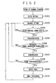
- Fig. 2 is a flowchart showing a processing of a channel search.
- the channel search is the processing to search a receivable channel, and it is enough that the processing is performed once, for example, at a time of installation of the television receiving apparatus 101.
- a step S201 when a start of the channel search is instructed, the following processings are performed.
- filter setting is carried out.
- a control signal 121 designates either a channel search mode or a normal reception mode.
- the selector 113 sets a filter coefficient Kb to the FIR type digital filter 112 when the control signal 121 designates the channel search mode, and sets a filter coefficient Ka to the FIR type digital filter 112 when the control signal 121 designates the normal reception mode.
- the filter coefficient Ka is set to the FIR type digital filter 112, since the channel search mode is designated.
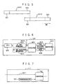
- Fig.3 is a diagram of a frequency spectrum showing pass frequency bands of the FIR type digital filter 112.
- An ISDB-T signal 303 is a terrestrial digital broadcast signal, while NTSC signals 305 and 306 are terrestrial analog broadcast signals.
- the NTSC signal 305 is a video carrier, while the NTSC signal 306 is a sound carrier.
- the ISDB-T signal 303 is a signal to be demodulated and has a plurality of TMCC signals 304 at specified frequency intervals (periodically).
- a frequency bandwidth of one channel CH is 6 MHz.
- the selector 113 sets the filter coefficient Ka to the FIR type digital filter 112. Then, the FIR type digital filter 112, to which a pass frequency band 301 is set, passes only a signal Ps for one channel CH.
- the frequency bands of the ISDB-T signal 303 and NTSC signals 305, 306 are overlapped.
- the selector 113 sets the filter coefficient Kb to the FIR type digital filter 112.
- the FIR type digital filter 112 to which a pass frequency band 302 is set, passes only a signal Pb. Since a single or a plurality of TMCC signal(s) 304 is (are) included in the signal Pb, it is possible to perform the channel search based on the signal Pb.
- misjudgment in the channel search can be prevented.
- the FIR type digital filter 112 filters a signal based on the pass frequency bands changed at the time of the channel search and at the time of the normal reception. Additionally, the FIR type digital filter 112 can reduce circuit scale since the FIR type digital filter 112 serves as the filter for both the normal reception and the channel search.
- the control circuit 118 instructs the tuner 103 which channel to receive.
- the control circuit 118 instructs receiving of Channel One.
- the tuner 103 outputs an ISDB-T signal of that channel to the A/D conversion unit 111.
- the A/D conversion unit 111 converts an input signal from an analog format to a digital format, and outputs to the FIR type digital filter 112.
- the FIR type digital filter 112, to which the pass frequency band 302 is set, passes only the signal Pb by filtering the input signals, and then outputs to the synchronization processing unit 115 and the demodulation processing unit 114.
- a process proceeds to a step S205, and if the correlation does not exist, that channel is judged to be unreceivable and the process returns to the step S203.
- a next channel for example, Channel Two
- the search processing of the next channel can be performed without the synchronization processing of the step S205, demodulation processing of a step S207 and a frame synchronization processing of a step S208 being performed, so that channel search time can be shortened.
- a detailed processing of the synchronization processing unit 115 will be described.
- Fig. 4 is a diagram showing a constitutional example of a part of the synchronization processing unit 115.
- An input signal A411 is an output signal of the FIR type digital filter 112.
- a delay processing unit 401 outputs a signal A412 made by delaying the input signal A411 by one symbol.
- Fig. 5 is a diagram showing one symbol amounts of the input signal A411 and the delay signal A412.
- Receive signals include a delay signal (signal arriving after reflected on a building or the like) in addition to a direct signal.
- a rear end portion 502 of the symbol is copied and made to be a front end portion 501.
- Making a signal into cyclic construction as described above is the guard interval. Therefore, the rear end portion 502 of the input signal A411 and the front end portion 501 of the delay signal A412 are the same, and a correlation value of the both in this guard interval period is high. If the correlation value is high, it is highly possible that the ISDB-T signal of that channel is receivable, and if the correlation value is low, the ISDB-T signal of that channel can be judged to be unreceivable.
- a correlation processing unit 402 calculates a correlation value of the input signal A411 and the delay signal A412 in the guard interval period.
- a peak detection unit 403 takes a moving average (integral) of the above correlation value and detects its peak value.
- a comparison unit 405 compares the peak value and a threshold value 404, and outputs a comparison result. When the peak value exceeds the threshold value 404, a correlation is judged to exist and the process proceeds to the step S205 of Fig. 2 . When the peak value is less than or equal to the threshold value 404, the correlation is judged not to exist and the process returns to the step S203 of Fig. 2 .
- the synchronization processing unit 115 performs the synchronization processing based on the output signal of the FIR type digital filter 112.
- the demodulation processing unit 114 judges the number of reference signals in the input signals and whether or not frequency allocation has a correlation with a predetermined one.
- the reference signal is a TMCC signal and/or an AC (Auxiliary Channel) signal.
- the A/C signal is a preliminary signal. If the correlation exists, the process proceeds to the step S207, and if the correlation does not exist, that channel is judged to be unreceivable and the process returns to the step S203. In the step S203, the next channel (for example, Channel Two) is set and the same processings are repeated.
- a search processing of the next channel can be performed without the demodulation processing of the step S207 and the frame synchronization processing in the step S208 being performed, so that channel search time can be shortened.
- a detailed processing of the demodulation processing unit 114 will be described.
- Fig. 6 is a diagram showing a constitutional example of a part of the demodulation processing unit 114.
- a fast Fourier transform (FFT) processing unit 601 transforms an input signal into a frequency component signal by FFT, and outputs to an AC and TMCC processing unit 602. For example, the signal Pb on a frequency axis of Fig. 3 is obtained.
- the AC and TMCC processing unit 602 detects the AC signal and TMCC signal A611 in the input signal.
- a correlation processing unit 604 calculates a correlation value of the number and frequency allocation of the AC signal and TMCC signal A611, and the number and frequency allocation information 603 of predetermined AC signal and TMCC signal.
- a peak detection unit 605 takes a moving average (integral) of the above correlation value and detects its peak value.
- a comparison unit 607 compares the peak value and a threshold value 606, and outputs a comparison result. When the peak value exceeds the threshold value 606, a correlation is judged to exist and the process proceeds to the step S207 of Fig. 2 . When the peak value is less than or equal to the threshold value 606, the correlation is judged not to exist and the process returns to the step S203 of Fig. 2 .
- the demodulation processing unit 114 performs the demodulation processing based on output signals of the FIR type digital filter 112 and the synchronization processing unit 115 at a predetermined timing, and outputs to the frame synchronization processing and TMCC detection unit 117 and the error correction processing unit 116.
- the demodulation processing includes an OFDM demodulation and a phase demodulation.
- the frame synchronization processing unit 117 performs a frame synchronization processing based on an output signal of the demodulation processing unit 114.
- One frame consists of 204 symbols.
- the frame synchronization processing unit 117 detects a synchronizing signal (synchronizing byte) in the output signals of the demodulation processing unit 114.
- the synchronizing signal cannot be detected, that channel is judged to be unreceivable and the process returns to the step S203.
- the next channel for example, Channel Two
- the frame synchronization processing is performed and the process proceeds to a step S209.
- a detailed processing of the frame synchronization processing unit 117 will be described.
- Fig. 7 is a diagram showing a constitutional example of a part of the frame synchronization processing unit 117.
- Input signals A611 are the AC signal and TMCC signal which the AC and TMCC processing unit 602 of Fig. 6 outputs.
- a comparison unit 702 compares whether or not the synchronizing signal (synchronizing byte) in the AC signal and TMCC signal A611, and a predetermined synchronizing signal (synchronizing byte) 701 have the same values, and outputs a comparison result thereof. If the values are the same, it is judged that the synchronizing signal is detected and the process proceeds to the step S209 of Fig. 2 . When the values are not the same, it is judged that the synchronizing signal cannot be detected and the process returns to the step S203 of Fig. 2 .
- the TMCC detection unit 117 detects TMCC information in a TMCC signal of the output signal of the demodulation processing unit 114.
- the TMCC information includes information of a phase (carrier) modulation scheme.
- an ISDB-T signal of that channel is judged to be receivable.
- the ISDB-T signal is a receive signal by a standard of terrestrial digital broadcast and adopts an OFDM modulation scheme.
- the control circuit 118 when a signal 122 to indicate receivablenss is inputted, performs a recording control to the memory 105 that the channel is receivable.
- the control circuit 118 also carries out a control such that channel information (number) 801 and TMCC information 802 are recorded correspondingly in the memory 105, as shown in Fig. 8 .
- the TMCC information 802 is the TMCC information detected in the step S209.
- the profess returns to the step S203.
- the next channel for example, Channel Two
- the same processings are repeated.
- the control circuit 118 inputs a control signal 122 indicating to that effect and can perform a recording control to the memory 105 that the channel is unreceivable.
- Judgment result signals 122 of the steps S204, S206 and S208 are respectively used for channel control of the tuner 103 by the control circuit 118.
- Fig. 9 is a flowchart showing a processing of the normal reception. After the above-described channel search is finished, the ISDB-T signal is received by the normal reception, and image and audio can be reproduced.
- step S901 when a start of the normal reception is instructed, the following processings are performed.
- step S902 filter setting is carried out.
- the selector 113 sets the filter coefficient Ka to the FIR type digital filter 112.
- the FIR type digital filter 112, to which the pass frequency band 301 is set passes only the signal Pa.
- the tuner 103 when the user designates a channel, the tuner 103 outputs an ISDB-T signal of the designated channel to the A/D conversion unit 111 of the OFDM demodulator 102.
- the A/D conversion unit 111 converts an input signal from an analog format to a digital format, and outputs to the FIR type digital filter 112.
- the FIR type digital filter 112 to which the pass frequency band 301 is set, passes only the signal Pa by filtering input signals, and outputs to the synchronization processing unit 115 and the demodulation processing unit 114.
- TMCC setting is carried out.
- the control circuit 118 reads out TMCC information 802 ( Fig. 8 ) corresponding to the channel from the memory 105 and set the information.
- the TMCC detection unit 117 can set the TMCC information 802 which has been read out to the error correction processing unit 116.
- step S904 the same synchronization processing as that of the step S205 of Fig. 2 is performed.
- step S905 the same demodulation processing as that of the step S207 is performed.
- step S906 the same frame synchronization processing as that of the step S208 is performed.
- the error correction processing unit 116 performs error correction based on output signals of the demodulation processing unit 114 and the frame synchronization processing and TMCC detection unit 117. Specifically, the error correction processing unit 116 error-corrects the output signal of the demodulation processing unit 114 using the TMCC information 802 set in the step S903, and outputs an MPEG 2 transport stream to the MPEG 2 decoder 104.
- the MPEG 2 decoder 104 decodes the MPEG 2 transport stream, and image and audio is reproduced.
- the TMCC detection processing of the step S209 of Fig. 2 is performed.
- the TMCC information detected there is used to perform the error correction.
- the TMCC detection processing between the steps S906 and S907 becomes unnecessary. Therefore, the normal reception processing can be made simple and fast.
- the TMCC detection unit 117 detects TMCC information in the input signal at the time of the channel search of Fig. 2 , and does not detect TMCC information at the time of the normal reception. At the time of the normal reception, the TMCC information in the memory 105 is used.
- the unnecessary NTSC signals 305, 306 can be removed by the filter 112, misjudgment in the channel search can be prevented.
- the synchronization processing of the step S205 and/or the demodulation of the step S207 is (are) carried out only when judgments in the steps S204 and S206 of Fig.2 satisfy predetermined conditions.
- the above-described synchronization processing and/or demodulation being (an) additional processing(s) can be omitted, and channel search time can be drastically shortened.
- channel search time can be shortened by performing the synchronization processing or demodulation when the predetermined condition is satisfied.
Landscapes
- Engineering & Computer Science (AREA)
- Signal Processing (AREA)
- Multimedia (AREA)
- Computer Networks & Wireless Communication (AREA)
- Circuits Of Receivers In General (AREA)
- Superheterodyne Receivers (AREA)
Claims (12)
- Démodulateur (102) comportant :un filtre (112) pour filtrer un signal en fonction de bandes passantes de fréquences changées au moment d'une recherche de canal et au moment d'une réception normale ; etune unité de traitement de démodulation (114) pour effectuer une démodulation par multiplexage par répartition en fréquence orthogonale en fonction du signal filtré, caractérisé en ce qu'il comporte en outre :une unité de traitement de synchronisation (115) pour effectuer un traitement de synchronisation en fonction du signal filtré ;une unité de traitement de synchronisation de trame (117) pour effectuer une détection d'un signal de synchronisation en fonction du signal démodulé ; etune unité de détection TMCC (117) pour détecter une information de contrôle de configuration de la transmission et du multiplexage (TMCC) en fonction du signal démodulé lorsque le signal de synchronisation est détecté,dans lequel ladite unité de traitement de démodulation (114) est agencée pour effectuer la démodulation par multiplexage par répartition en fréquence orthogonale en fonction du signal traité de synchronisation, etdans lequel ladite unité de traitement de démodulation (114) est agencée pour effectuer la démodulation par multiplexage par répartition en fréquence orthogonale après le traitement de synchronisation lorsqu'une allocation de fréquence d'un signal de référence dans le signal filtré satisfait une condition.
- Démodulateur selon la revendication 1, dans lequel l'information TMCC comprend une information d'un schéma de modulation de phase.
- Démodulateur selon la revendication 2, dans lequel ladite unité de traitement de synchronisation est agencée pour calculer une valeur de corrélation d'un signal qui est un signal d'entrée retardé et le signal d'entrée, et pour effectuer le traitement de synchronisation lorsque la valeur de corrélation satisfait une condition.
- Démodulateur selon la revendication 1, dans lequel le signal de référence est un signal TMCC et/ou un signal de canal auxiliaire AC.
- Démodulateur selon la revendication 4, comportant en outre une unité de contrôle d'enregistrement pour effectuer un contrôle de sorte que l'information TMCC détectée et l'information de canal sont enregistrées de façon correspondante.
- Démodulateur selon la revendication 5, comportant en outre une unité de traitement de correction d'erreur pour effectuer une correction d'erreur du signal démodulé en fonction de l'information TMCC détectée.
- Démodulateur selon la revendication 6, dans lequel ladite unité de détection TMCC est agencée pour détecter une information TMCC au moment de la recherche de canal et pour ne pas détecter une information TMCC au moment de la réception normale, et
dans lequel ladite unité de traitement de correction d'erreur est agencée pour effectuer une correction d'erreur en fonction de l'information TMCC enregistrée, au moment de la réception normale. - Démodulateur selon la revendication 4, comportant en outre une unité de contrôle d'enregistrement pour effectuer un contrôle de sorte que l'information TMCC détectée et l'information de canal sont enregistrées de façon correspondante.
- Démodulateur selon la revendication 8, comportant en outre une unité de traitement de correction d'erreur pour effectuer une correction d'erreur du signal démodulé en fonction de l'information TMCC détectée.
- Démodulateur selon la revendication 9, dans lequel ladite unité de détection TMCC est agencée pour détecter une information TMCC au moment de la recherche de canal et pour ne pas détecter l'information TMCC au moment de la réception normale, et
dans lequel ladite unité de traitement de correction d'erreur est agencée pour effectuer la correction d'erreur en fonction de l'information TMCC enregistrée, au moment de la réception normale. - Démodulateur (102) comportant :une unité de traitement de synchronisation (115) pour effectuer un traitement de synchronisation en fonction d'un signal d'entrée ; etune unité de traitement de démodulation (114) pour effectuer une démodulation par multiplexage par répartition en fréquence orthogonale en fonction du signal de synchronisation traité, etdans lequel ladite unité de traitement de démodulation est agencée pour effectuer la démodulation par multiplexage par répartition en fréquence orthogonale lorsqu'une allocation de fréquence d'un signal de référence dans le signal d'entrée satisfait une condition.
- Démodulateur selon la revendication 11, dans lequel le signal de référence est un signal TMCC et/ou un signal de canal auxiliaire AC.
Applications Claiming Priority (1)
| Application Number | Priority Date | Filing Date | Title |
|---|---|---|---|
| JP2005217216A JP2007036684A (ja) | 2005-07-27 | 2005-07-27 | 復調装置 |
Publications (3)
| Publication Number | Publication Date |
|---|---|
| EP1748613A2 EP1748613A2 (fr) | 2007-01-31 |
| EP1748613A3 EP1748613A3 (fr) | 2008-02-13 |
| EP1748613B1 true EP1748613B1 (fr) | 2009-03-11 |
Family
ID=37198704
Family Applications (1)
| Application Number | Title | Priority Date | Filing Date |
|---|---|---|---|
| EP06251308A Expired - Fee Related EP1748613B1 (fr) | 2005-07-27 | 2006-03-13 | Démodulateur |
Country Status (3)
| Country | Link |
|---|---|
| US (1) | US20070025472A1 (fr) |
| EP (1) | EP1748613B1 (fr) |
| JP (1) | JP2007036684A (fr) |
Families Citing this family (7)
| Publication number | Priority date | Publication date | Assignee | Title |
|---|---|---|---|---|
| KR101204513B1 (ko) * | 2005-12-20 | 2012-11-26 | 삼성전자주식회사 | 디지털 멀티미디어 재생 장치 및 디지털 멀티미디어 재생장치에서 디지털 멀티미디어 방송을 제공하는 방법 |
| JP4949738B2 (ja) * | 2006-05-29 | 2012-06-13 | 富士通セミコンダクター株式会社 | デジタル放送受信機、移動端末およびチャネルサーチ方法 |
| CN104299024B (zh) * | 2013-07-19 | 2018-08-21 | 上海华虹宏力半导体制造有限公司 | 非接触ic卡的解调电路 |
| KR101491651B1 (ko) * | 2013-08-14 | 2015-02-09 | (주)에프씨아이 | 고속 전송다중제어 데이터 획득 방법 및 장치 |
| WO2019221080A1 (fr) * | 2018-05-15 | 2019-11-21 | マクセル株式会社 | Dispositif de réception de diffusion et procédé de traitement d'onde porteuse |
| JP7102220B2 (ja) * | 2018-05-15 | 2022-07-19 | マクセル株式会社 | 伝送波の処理方法 |
| JP7131768B2 (ja) * | 2018-08-10 | 2022-09-06 | 株式会社国際電気通信基礎技術研究所 | 通信推定装置、コンピュータに実行させるためのプログラムおよびプログラムを記録したコンピュータ読み取り可能な記録媒体 |
Family Cites Families (7)
| Publication number | Priority date | Publication date | Assignee | Title |
|---|---|---|---|---|
| FI105963B (fi) * | 1998-08-24 | 2000-10-31 | Nokia Oyj | Menetelmä opetusjakson muodostamiseksi |
| US20020157106A1 (en) * | 2001-04-18 | 2002-10-24 | Robert Uskali | Cable channel search systems |
| FR2831015B1 (fr) * | 2001-10-15 | 2004-01-02 | Thomson Licensing Sa | Procede de detection de canaux de transmission et dispositif de reception utilisant le procede |
| JP3693025B2 (ja) * | 2002-02-21 | 2005-09-07 | ソニー株式会社 | 無線通信方法、無線通信システム、無線基地局、無線通信端末、プログラム及び媒体 |
| KR100503091B1 (ko) * | 2003-07-28 | 2005-07-21 | 삼성전자주식회사 | 디지털 텔레비전의 채널 스캔 방법 |
| JP4397205B2 (ja) * | 2003-10-02 | 2010-01-13 | 三洋電機株式会社 | 放送受信装置 |
| WO2006090337A2 (fr) * | 2005-02-25 | 2006-08-31 | Koninklijke Philips Electronics N.V. | Procede et dispositif de synchronisation pour recepteur sans fil |
-
2005
- 2005-07-27 JP JP2005217216A patent/JP2007036684A/ja active Pending
-
2006
- 2006-03-10 US US11/372,391 patent/US20070025472A1/en not_active Abandoned
- 2006-03-13 EP EP06251308A patent/EP1748613B1/fr not_active Expired - Fee Related
Also Published As
| Publication number | Publication date |
|---|---|
| EP1748613A2 (fr) | 2007-01-31 |
| JP2007036684A (ja) | 2007-02-08 |
| US20070025472A1 (en) | 2007-02-01 |
| EP1748613A3 (fr) | 2008-02-13 |
Similar Documents
| Publication | Publication Date | Title |
|---|---|---|
| US8121566B2 (en) | Broadcast receiver and broadcast channel seek method | |
| JP2000013357A (ja) | Ofdm受信装置 | |
| CN1612558B (zh) | Ofdm解调装置以及ofdm解调方法 | |
| EP0788264A2 (fr) | Emetteur et récepteur pour MDFO | |
| EP1748613A2 (fr) | Démodulateur | |
| US7460147B2 (en) | Interference detecting circuit utilizing synchronization symbols and method thereof | |
| US8184741B2 (en) | Multi-system signal receiving device and method thereof | |
| JP2003069907A (ja) | 地上デジタル放送受信装置 | |
| US8265585B2 (en) | IBOC broadcasting receiver | |
| US12149335B2 (en) | Method for improving audio acquisition time by nascent signal caching | |
| JP4637265B2 (ja) | デジタル放送受信装置 | |
| JP2004236076A (ja) | 受信装置及び受信方法 | |
| US8160523B2 (en) | Channel detecting method for digital broadcast and receiver using the same | |
| KR101092551B1 (ko) | 디지털 방송 수신기 및 디지털 방송 수신 모듈 | |
| EP0949772B1 (fr) | Demodulateur des signaux RDS pour la réception de programmes de radiodiffusion comportant à la fois un signal RDS et un signal ARI, avec un dispositif de filtrage numérique assurant une attenuation élevée du signal ARI | |
| JP4440050B2 (ja) | 受信装置 | |
| JP4622598B2 (ja) | 受信回路 | |
| JP5278791B2 (ja) | 受信装置及びチャネルスキャン方法 | |
| JP2006287342A (ja) | ギャップフィラー装置 | |
| HK1139265A1 (en) | A digital multimedia receiver and a digital multimedia receiving method thereof | |
| JP2009152817A (ja) | デジタル放送受信装置及びデジタル放送受信装置における隣接妨害検出方法 | |
| KR20020061839A (ko) | 디지털 티브이의 ntsc 인접 채널 간섭 제거 장치 | |
| HK1139265B (en) | A digital multimedia receiver and a digital multimedia receiving method thereof | |
| HK1128568A (en) | A digital multimedia receiver and a digital multimedia receiving method thereof | |
| JP2008053968A (ja) | 地上デジタル音声放送受信機及びその選局制御方法 |
Legal Events
| Date | Code | Title | Description |
|---|---|---|---|
| PUAI | Public reference made under article 153(3) epc to a published international application that has entered the european phase |
Free format text: ORIGINAL CODE: 0009012 |
|
| AK | Designated contracting states |
Kind code of ref document: A2 Designated state(s): AT BE BG CH CY CZ DE DK EE ES FI FR GB GR HU IE IS IT LI LT LU LV MC NL PL PT RO SE SI SK TR |
|
| AX | Request for extension of the european patent |
Extension state: AL BA HR MK YU |
|
| PUAL | Search report despatched |
Free format text: ORIGINAL CODE: 0009013 |
|
| RIC1 | Information provided on ipc code assigned before grant |
Ipc: H04N 5/44 20060101ALI20071221BHEP Ipc: H04L 27/26 20060101AFI20061108BHEP Ipc: H03J 5/00 20060101ALI20071221BHEP Ipc: H04B 1/10 20060101ALI20071221BHEP |
|
| AK | Designated contracting states |
Kind code of ref document: A3 Designated state(s): AT BE BG CH CY CZ DE DK EE ES FI FR GB GR HU IE IS IT LI LT LU LV MC NL PL PT RO SE SI SK TR |
|
| AX | Request for extension of the european patent |
Extension state: AL BA HR MK YU |
|
| 17P | Request for examination filed |
Effective date: 20080806 |
|
| GRAP | Despatch of communication of intention to grant a patent |
Free format text: ORIGINAL CODE: EPIDOSNIGR1 |
|
| AKX | Designation fees paid |
Designated state(s): DE FR GB |
|
| GRAS | Grant fee paid |
Free format text: ORIGINAL CODE: EPIDOSNIGR3 |
|
| GRAA | (expected) grant |
Free format text: ORIGINAL CODE: 0009210 |
|
| AK | Designated contracting states |
Kind code of ref document: B1 Designated state(s): FR |
|
| PLBE | No opposition filed within time limit |
Free format text: ORIGINAL CODE: 0009261 |
|
| STAA | Information on the status of an ep patent application or granted ep patent |
Free format text: STATUS: NO OPPOSITION FILED WITHIN TIME LIMIT |
|
| 26N | No opposition filed |
Effective date: 20091214 |
|
| PGFP | Annual fee paid to national office [announced via postgrant information from national office to epo] |
Ref country code: FR Payment date: 20100324 Year of fee payment: 5 |
|
| REG | Reference to a national code |
Ref country code: FR Ref legal event code: ST Effective date: 20111130 |
|
| PG25 | Lapsed in a contracting state [announced via postgrant information from national office to epo] |
Ref country code: FR Free format text: LAPSE BECAUSE OF NON-PAYMENT OF DUE FEES Effective date: 20110331 |