EP1749792A2 - Füllelement - Google Patents
Füllelement Download PDFInfo
- Publication number
- EP1749792A2 EP1749792A2 EP06014207A EP06014207A EP1749792A2 EP 1749792 A2 EP1749792 A2 EP 1749792A2 EP 06014207 A EP06014207 A EP 06014207A EP 06014207 A EP06014207 A EP 06014207A EP 1749792 A2 EP1749792 A2 EP 1749792A2
- Authority
- EP
- European Patent Office
- Prior art keywords
- filling
- flushing
- receptacle
- flushing cap
- element according
- Prior art date
- Legal status (The legal status is an assumption and is not a legal conclusion. Google has not performed a legal analysis and makes no representation as to the accuracy of the status listed.)
- Granted
Links
Images


Classifications
-
- B—PERFORMING OPERATIONS; TRANSPORTING
- B67—OPENING, CLOSING OR CLEANING BOTTLES, JARS OR SIMILAR CONTAINERS; LIQUID HANDLING
- B67C—CLEANING, FILLING WITH LIQUIDS OR SEMILIQUIDS, OR EMPTYING, OF BOTTLES, JARS, CANS, CASKS, BARRELS, OR SIMILAR CONTAINERS, NOT OTHERWISE PROVIDED FOR; FUNNELS
- B67C3/00—Bottling liquids or semiliquids; Filling jars or cans with liquids or semiliquids using bottling or like apparatus; Filling casks or barrels with liquids or semiliquids
- B67C3/001—Cleaning of filling devices
- B67C3/002—Cleaning of filling devices using cups or dummies to be placed under the filling heads
- B67C3/004—Cleaning of filling devices using cups or dummies to be placed under the filling heads permanently attached to the filling machine and movable between a rest and a working position
Definitions
- the present invention relates to a filling element with flushing cap according to the preamble of claim 1.
- Advantageous further developments are specified in the subclaims.
- Filling elements especially those for use in filling machines rotating design are known in various designs. It is also known to clean and / or to flush these filling elements as well as the surfaces of the filling elements coming into contact with critical areas of the containers in a cleaning or rinsing phase with, for example, a liquid and / or vaporous medium. Critical areas of the containers are in particular container inner surfaces and areas in the region of the container mouth.
- cap-like closing elements For the cleaning and / or rinsing of the filling elements, it is common and known to attach, for example, cap-like closing elements to the filling elements in the region of the discharge openings, via which the liquid contents are introduced into the containers during filling, specifically to form closed rinsing areas.
- cap-like closing elements are hereinafter called flushing caps.
- the cleaning and / or rinsing of the filling elements, including their channels and their surfaces coming into contact with critical areas of the containers during filling, which may also be sealing surfaces, is then assisted by the u.a.
- the flushing and cleaning medium flowing through the respective closed flushing chamber is possible, which flows to the flushing chamber, for example via the respective discharge opening of the liquid channel and is discharged via at least one further, also in the flushing chamber opening, for example via the return gas channel.
- bottles made of glass with almost any diameter ratios between the largest diameter of the bottle and the mouth diameter can be produced. Whereas only small diameter ratios between the largest and smallest diameter of the can are possible in the production of conventional tin cans.
- the filling points of can filling machines can have a smaller distance from each other than the filling points of bottle filling machines, as bottle filling machines should also be able to fill, for example, bulbous shaped bottles.
- a device for the automatic operation of Spülkappen was eg in the JP9-309593 A presented.
- two Spülkappen are each received by a support member, wherein the support member is held on a, arranged radially on the rotating top of the filling machine carriage.
- This slide in turn is radially movable from a first, inner position to a second outer position, whereby the flushing caps are brought into operative connection with the associated filling valves.
- the guides and thus also the force-receiving points of the carriage are located between the associated filling valves at a radially inner position.
- the cans to be filled by can filling machines have diameters between 53 and for example 82 mm.
- the filling valves and thus also the associated flushing caps have corresponding diameters.
- the cleaning or flushing of the filling valves takes place with pressures of up to 3 * 10 5 Pa. From these parameters results per flushing cap, a force of up to 1500 N, which can in conjunction with the unfavorably arranged points of force application elastic deformation of the Spülkappenbefest Trent by itself.
- this device eliminates the disadvantage of unfavorable force application points, but the arrangement of the receiving elements on the pitch circle of the centers of the filling valves proves to be particularly disadvantageous because the individual filling elements may have to be arranged at an increased distance from each other. Also, such a device is mechanically complex and expensive.
- the object of the invention is therefore to show a filling element equipped with a flushing cap, which avoids these disadvantages and which is held in the sealing position such that leaks and leaks are reliably avoided.
- a filling element according to the patent claim 1 is formed.
- the flushing cap arranged or received in a receptacle is moved from a first, radially inner non-engagement position into a second, radially outer engagement position to form the respective closed flushing space, the flushing cap being fixed by an additional retaining element to maintain the sealing seat becomes.
- FIGS. 3 and 4 a further embodiment of the present invention.
- the flushing cap 13 can be moved from a first, radially inner non-engagement position A into a second, radially outer engagement position B.
- the adjustment can be done in a conventional manner, for example, by means of a curved path control 14.
- the guides 17 of the flushing caps 13 are not arranged on the pitch circle of the center points of the filling valves and thus between the individual tulips 16, but rather on a radially inner position.
- the sealing layer during the flushing process to receive the flushing cap 13 in at least one further element, for example a receptacle 18, in its radially outer engagement position B.
- the front receptacles 18 of the Spülkappen 13 rotate with the gyro of the can filling machine, it may happen that the receptacles 18 in particular in the range of Dosenein- or -auslaufs in the gyro of the filling machine in the way of the cans 15 at certain geometrical dimensions of the components protrude.
- the receptacles 18 in such a way that they can be brought between a non-engagement position and an engagement position.
- the receptacles 18 can be made pivotable about a horizontal axis, so that the receptacles 18 can be pivoted after the completion of the flushing operation in the non-engagement position, and thus do not hinder the inlet and outlet of the cans.
- the control of the pivoting movements of the seats 18 takes place by means of a cam or curved path control, in which e.g. a pivoting lever 20 transmits the movements predetermined by the curved path to the receptacle 18.
- pivoting movement of the receptacles 18 can also be achieved in other ways, e.g. using controlled or regulated stepper, servo or synchronous motors.
- the tulip 16 in such a way that it can perform an extended lifting movement.
- the tulip 16 performs only a normal stroke h, which is sufficient to the cans 15th seal and release. For rinsing and / or cleaning the filling element, the tulip 16 performs a large lifting movement H, which clears the path of the flushing cap 13, so that the flushing cap 13 can enter into active engagement with the receptacle 18.
Landscapes
- Filling Of Jars Or Cans And Processes For Cleaning And Sealing Jars (AREA)
Abstract
Description
- Die vorliegende Erfindung betrifft ein Füllelement mit Spülkappe gemäß dem Oberbegriff des Anspruches 1. Vorteilhafte Weiterbildungen sind in den Unteransprüchen angegeben.
- Füllelemente, insbesondere auch solche zur Verwendung bei Füllmaschinen umlaufender Bauart sind in unterschiedlichsten Ausführungen bekannt. Bekannt ist ferner, diese Füllelemente sowie die beim Füllen mit kritischen Bereichen der Behälter in Berührung kommenden Flächen der Füllelemente in einer Reinigungs-oder Spülphase mit einem beispielsweise flüssigen und/oder dampfförmigen Medium zu reinigen und/oder zu spülen. Kritische Bereiche der Behälter sind insbesondere Behälterinnenflächen sowie Flächen im Bereich der Behältermündung.
- Für das Reinigen und/oder Spülen der Füllelemente ist es üblich und bekannt, an den Füllelementen im Bereich der Abgabeöffnungen, über die beim Füllen das flüssige Füllgut in die Behälter eingeleitet wird, beispielsweise kappenartige Verschließelemente anzubringen, und zwar zur Bildung geschlossener Spülräume. Diese kappenartigen Verschließelemente werden nachfolgend Spülkappen genannt.
- Das Reinigen und/oder Spülen der Füllelemente, einschließlich deren Kanäle und deren mit kritischen Bereichen der Behälter beim Füllen in Berührung kommenden Flächen, wobei es sich auch um Dichtungsflächen handeln kann, ist dann durch das u.a. den jeweiligen geschlossenen Spülraum durchströmende Spül- und Reinigungsmedium möglich, welches dem Spülraum beispielsweise über die jeweilige Abgabeöffnung des Flüssigkeitskanals zufließt und über wenigstens einen weiteren, ebenfalls in den Spülraum mündenden Kanal, beispielsweise über den Rückgaskanal abgeführt wird.
- Das Aufsetzen und Fixieren der Spülkappen zur Vorbereitung der Spül- oder Reinigungsphase sowie das Abnehmen dieser Spülkappen nach der Spül- und Reinigungsphase ist aufwendig und teuer.
- Da die Handhabung der Spülkappen insbesondere dann zeitaufwändig und teuer ist, wenn die dazu erforderlichen Tätigkeiten manuell ausgeführt werden, wurden in der Vergangenheit zahlreiche Vorschläge unterbreitet wurden, um diese Tätigkeiten zu automatisieren.
- In diesem Zusammenhang ist zu beachten, dass aus Glas bestehende Flaschen mit nahezu beliebigen Durchmesserverhältnissen zwischen größtem Durchmesser der Flasche und dem Mündungsdurchmesser herstellbar sind. Wohingegen bei der Herstellung von üblicher Weise aus Blech bestehenden Dosen lediglich kleine Durchmesserverhältnisse zwischen größtem und kleinstem Durchmesser der Dose möglich sind.
- Aus diesem Sachverhalt ergibt sich, dass die Füllstellen von Dosenfüllmaschinen einen kleineren Abstand von einander aufweisen können, als die Füllstellen von Flaschenfüllmaschinen, da Flaschenfüllmaschinen auch in der Lage sein sollen, z.B bauchige Formflaschen abzufüllen.
- Aus Gründen der Kostenreduzierung werden somit die Füllstellen von Dosenfüllmaschinen sehr dicht nebeneinander angeordnet, wodurch sich Schwierigkeiten bei der Anordnung automatisch verfahrbarer Spülkappen ergeben.
- Eine Vorrichtung zum automatischen Verfahren von Spülkappen wurde z.B in der
JP9-309593 A
Die Führungen und somit auch die Kraftaufnahmepunkte des Schlittens befinden sich zwischen den zugeordneten Füllventilen an einer radial inneren Position. - Aus dieser geometrischen Anordnung ergibt sich ein wesentlicher Nachteil einer Vorrichtung entsprechend der
JP9-309593 A - Die von Dosenfüllmaschinen abzufüllenden Dosen weisen Durchmesser zwischen 53 und beispielsweise 82 mm auf. Die Füllventile und somit auch die zugeordneten Spülkappen weisen entsprechende Durchmesser auf. Die Reinigung bzw. Spülung der Füllventile erfolgt mit Drücken von bis zu 3*105 Pa.
Aus diesen Parametern ergibt sich je Spülkappe eine Kraft von bis zu 1500 N, welche in Verbindung mit den ungünstig angeordneten Kraftangriffspunkten eine elastische Verformung der Spülkappenbefestigung nach sich ziehen kann. - In der Praxis wurde es häufig beobachtet, dass die Dichtungen der Spülkappen in Folge dieser elastischen Verformungen ihre Dichtfunktion ganz oder teilweise einbüßen, wodurch die unter hohem Druck stehende Spül- oder Reinigungsflüssigkeit austritt und das Füllventil und/oder die Füllmaschine verschmutzt.
- Dieses wird allgemein als Nachteil angesehen.
- Ebenfalls bekannt wurde eine Vorrichtung entsprechend der
DE 9403832 .
Bei dieser Vorrichtung wurden die, die eigentliche Dichtverbindung zwischen Dose und Füllventil herstellende höhenbewegliche Tulpe innerhalb eines umschließenden Rohres angeordnet. Aus dieses, die Tulpe umschließende Rohr wurden Elemente zur Aufnahme der Spülkappe angebracht, wobei diese Aufnahmeelemente auf dem Teilkreis der Füllventile angeordnet sind. - Zwar beseitigt diese Vorrichtung den Nachteil der ungünstigen Kraftangriffspunkte, doch erweist sich die Anordnung der Aufnahmeelemente auf dem Teilkreis der Mittelpunkte der Füllventile als besonders nachteilig, da die einzelnen Füllelemente unter Umständen mit einem vergrößerten Abstand zueinander angeordnet werden müssen. Ebenfalls ist eine derartige Vorrichtung mechanisch aufwändig und teuer.
- Aufgabe der Erfindung ist es daher, ein mit einer Spülkappe ausgestattetes Füllelement aufzuzeigen, welches diese Nachteile vermeidet und welches derart in der Dichtlage gehalten wird, dass Undichtigkeiten und Leckagen sicher vermieden werden. Zur Lösung dieser Aufgabe ist ein Füllelement entsprechend dem Patentanspruch 1 ausgebildet.
- Bei dem erfindungsgemäßen Füllelement wird die in einer Aufnahme angeordnete bzw. aufgenommene Spülkappe zur Bildung des jeweiligen geschlossenen Spülraumes aus einer ersten, radial inneren Nicht-Eingriffspositon in eine zweite, radial äußere Eingriffsposition verfahren, wobei die Spülkappe zur Aufrechterhaltung des Dichtsitzes durch ein zusätzliches Halteelement fixiert wird.
- Im Nachfolgenden wird die vorliegende Erfindung anhand zweier Ausführungsbeispiele näher erläutert.
-
- Figur 1
- in einer vereinfachten Schnittdarstellung ein erfindungsgemäßes Füllventil, die
- Figur 2
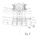
- in einer Draufsicht ausschnittsweise den Teilkreis einer Dosenfüllmaschine in Rundläuferbauweise, die
- Figuren 3 und 4 eine weiteres Ausführungsbeispiel der vorliegenden Erfindung.
- Weiterbildungen, Vorteile und Anwendungsmöglichkeiten der Erfindung ergeben sich aus der nachfolgenden Beschreibung von Ausführungsbeispielen und der Zeichnung. Dabei bilden alle beschriebenen und/oder bildlich dargestellten Merkmale für sich oder in beliebiger Kombination den Gegenstand der Erfindung, unabhängig von ihrer Zusammenfassung in den Ansprüchen oder deren Rückbeziehung. Gleichzeitig wird der Inhalt der Ansprüche zu einem Bestandteil der Beschreibung gemacht.
- Wie in der Figur 1 dargestellt, kann die Spülkappe 13 aus einer ersten, radial inneren Nicht-Eingriffsposition A in eine zweite, radial äußere Eingriffsposition B verbracht werden. Die Verstellbewegung kann in an sich bekannter Weise beispielsweise anhand einer Kurvenbahnsteuerung 14 erfolgen.
- Aufgrund der bei Dosenfüllmaschinen sehr engen Anordnung der Füllelemente verbleiben zwischen den einzelnen, die Dichtverbindung zu den Dosen 15 herstellenden Tulpen 16 lediglich wenige Millimeter Bauraum.
- Dementsprechend ist in an sich bekannter Weise zunächst vorgesehen, die Führungen 17 der Spülkappen 13 nicht auf dem Teilkreis der Mittelpunkte der Füllventile und somit zwischen den einzelnen Tulpen 16, sondern an einer radial inneren Position anzuordnen.
- Erfindungsgemäß ist zur Beibehaltung der Dichtlage während des Spülvorganges vorgesehen, die Spülkappe 13 in ihrer radial äußeren Eingriffsposition B in mindestens einem weiteren Element, beispielsweise einer Aufnahme 18 aufzunehmen.
- Dabei ist vorzugsweise vorgesehen, die Spülkappe 13 mit ihrem vorderen Ende in der mindestens einen Aufnahme 18 aufzunehmen, wobei es von besonderem Vorteil ist, die mindestens eine Aufnahme 18 bezogen auf die Drehachse der Dosenfüllmaschine, radial außerhalb des Teilkreises der Füllventile anzuordnen.
- Dadurch, dass die Spülkappe 13 während des Spülvorganges durch die Aufnahme 18 zusätzlich abgestützt wird, werden die Kraftverhältnisse der gesamten Anordnung grundlegend verbessert, so dass die bislang auftretenden elastischen Verformungen vermieden werden, wodurch eine sichere Beibehaltung der Dichtlage zwischen der, innerhalb der Tulpe 16 angeordneten Ringdichtung 19 und der Spülkappe 13 gewährleistet wird.
- Da die vorderen Aufnahmen 18 der Spülkappen 13 mit dem Kreisel der Dosenfüllmaschine umlaufen, kann es bei bestimmten geometrischen Abmessungen der Bauteile dazu kommen, dass die Aufnahmen 18 insbesondere im Bereich des Dosenein- oder -auslaufs in den Kreisel der Füllmaschine in den Weg der Dosen 15 ragen.
- Zur Vermeidung derartiger Probleme ist in einer besonders vorteilhaften Weiterbildung der vorliegenden Erfindung vorgesehen, die Aufnahmen 18 derart auszubilden, dass diese zwischen einer Nicht-Eingriffsposition und einer Eingriffsposition verbringbar sind.
- Beispielweise können die Aufnahmen 18 um eine horizontale Achse schwenkbar ausgeführt sein, so dass die Aufnahmen 18 nach der Beendigung des Spülvorganges in die Nicht-Eingriffsposition geschwenkt werden können, und somit den Ein- und Auslauf der Dosen nicht behindern.
- Vorzugsweise erfolgt die Steuerung der Schwenkbewegungen der Aufnahmen 18 anhand einer Kurven- oder Kurvenbahn-Steuerung, bei welcher z.B. ein Schwenkhebel 20 die durch die Kurvenbahn vorgegebenen Bewegungen auf die Aufnahme 18 überträgt.
- Die Schwenkbewegung der Aufnahmen 18 kann aber auch auf andere Art und Weise, z.B. anhand gesteuerter oder geregelter Schritt-, Servo- oder Synchronmotoren erfolgen.
- In einer weiteren Ausgestaltung der vorliegenden Erfindung ist vorgesehen, die Bauteile des Füllventils derart zu gestalten, dass die Aufnahme 18 trotz einer unbeweglichen Ausbildung den Ein- und Auslauf der Dosen 15 nicht behindert.
- Wie in den Figuren 3 und 4 dargestellt, ist diesbezüglich vorgesehen, die Tulpe 16 derart auszugestalten, dass diese eine erweiterte Hubbewegung ausführen kann.
- Während der normalen Abfüllung der Dosen 15 führt die Tulpe 16 lediglich eine normale Hubbewegung h aus, welche ausreichend ist, um die Dosen 15 abzudichten und wieder freizugeben. Zum Spülen und/oder Reinigen des Füllelementes führt die Tulpe 16 eine große Hubbewegung H aus, welche den Weg der Spülkappe 13 freigibt, so dass die Spülkappe 13 mit der Aufnahme 18 in eine Wirkverbindung treten kann.
Claims (6)
- Füllelement zur Anwendung an Rundläuferfüllmaschinen zur Abfüllung von Dosen oder dergleichen Behälter, mit einer Spülkappe (13), welche zwischen einer radial inneren Nicht-Eingriffsposition und einer radial äußeren Eingriffsposition verfahrbar ist, wobei die Spülkappe (13) durch radial innenliegende Führungen (17) aufgenommen und geführt ist, dadurch gekennzeichnet, dass die Spülkappe (13) in ihrer Eingriffsposition durch mindestens eine Aufnahme (18) zusätzlich aufgenommen und/oder gehalten ist.
- Füllelement nach Anspruch 1, dadurch gekennzeichnet, dass die mindestens eine Aufnahme (18) bezogen auf die Drehachse der Dosenfüllmaschine, radial außerhalb des Teilkreises der Mittelpunkte Füllventile angeordnet ist.
- Füllelement nach Anspruch 1 oder 2, dadurch gekennzeichnet, dass die mindestens eine Aufnahme (18) die Spülkappe (13) an deren radial äußeren Stirnfläche und/oder deren radial äußeren Seitenflächen aufnimmt.
- Füllelement nach einem der vorhergehenden Ansprüche, dadurch gekennzeichnet, dass die mindestens eine Aufnahme (18) in eine Nicht-Eingriffsposition und eine Eingriffsposition verbringbar ist.
- Füllelement nach Anspruch 4, dadurch gekennzeichnet, dass die Bewegung der Aufnahme (18) durch eine Kurven- oder Kurvenbahnsteuerung erfolgt.
- Füllelement nach einem der Ansprüche 1 bis 3, dadurch gekennzeichnet, dass der Hub der Tuple (16) so groß ist, dass diese aus dem Weg oder der Bewegungsebene der Spülkappe (13) zwischen ihrer Nicht-Eingriffsposition und ihrer Eingriffsposition entfernbar ist.
Priority Applications (2)
| Application Number | Priority Date | Filing Date | Title |
|---|---|---|---|
| SI200631564T SI1749792T1 (sl) | 2005-08-06 | 2006-07-08 | Dodatni nosilec s splakovalnim pokrovom |
| PL06014207T PL1749792T3 (pl) | 2005-08-06 | 2006-07-08 | Dodatkowe kotwienie kołpaka płuczącego |
Applications Claiming Priority (1)
| Application Number | Priority Date | Filing Date | Title |
|---|---|---|---|
| DE102005037127A DE102005037127B4 (de) | 2005-08-06 | 2005-08-06 | Füllelement mit Spülkappe |
Publications (3)
| Publication Number | Publication Date |
|---|---|
| EP1749792A2 true EP1749792A2 (de) | 2007-02-07 |
| EP1749792A3 EP1749792A3 (de) | 2008-05-28 |
| EP1749792B1 EP1749792B1 (de) | 2013-04-10 |
Family
ID=37575030
Family Applications (1)
| Application Number | Title | Priority Date | Filing Date |
|---|---|---|---|
| EP06014207.2A Expired - Lifetime EP1749792B1 (de) | 2005-08-06 | 2006-07-08 | Zusätzliche Verankerung einer Spülkappe |
Country Status (6)
| Country | Link |
|---|---|
| US (1) | US7513279B2 (de) |
| EP (1) | EP1749792B1 (de) |
| JP (1) | JP2007045527A (de) |
| DE (1) | DE102005037127B4 (de) |
| PL (1) | PL1749792T3 (de) |
| SI (1) | SI1749792T1 (de) |
Cited By (1)
| Publication number | Priority date | Publication date | Assignee | Title |
|---|---|---|---|---|
| CN114572476A (zh) * | 2022-03-27 | 2022-06-03 | 广州市华晟健康产业有限公司 | 一种厨房重油污除油剂灌装设备 |
Families Citing this family (10)
| Publication number | Priority date | Publication date | Assignee | Title |
|---|---|---|---|---|
| ITBO20060107A1 (it) * | 2006-02-14 | 2007-08-15 | Azionaria Costruzioni Acma Spa | Giostra per il trattamento di contenitori con prodotti liquidi o in polvere. |
| DE102007022259A1 (de) * | 2007-05-09 | 2009-01-15 | Khs Ag | Füllsystem sowie Verfahren zum Steuern eines Füllsystems |
| EP2374194A1 (de) * | 2009-01-06 | 2011-10-12 | Access Business Group International LLC | Drahtloses ladesystem mit geräteleistungskonformität |
| DE102009033557A1 (de) * | 2009-07-16 | 2011-01-20 | Krones Ag | Vorrichtung zum Abfüllen von Getränken mit CIP-Kappen-Steuerung |
| DE102010045268A1 (de) | 2010-09-14 | 2012-03-15 | Khs Gmbh | Reinigungsroboter mit Multifunktion |
| US9428373B2 (en) * | 2011-04-06 | 2016-08-30 | Mitsubishi Heavy Industries Food & Packaging Machine Co., Ltd. | Rotary-type filling machine and method for calculating filling quantity for rotary-type filling machine |
| US9302800B2 (en) | 2014-01-06 | 2016-04-05 | Cnjfw & Son, Llc | System and method for forming fluid mixtures |
| DE102014109589A1 (de) * | 2014-07-09 | 2016-01-14 | Khs Gmbh | Füllsystem zum Füllen von Flaschen oder dergleichen Behältern |
| US12391532B2 (en) * | 2021-04-06 | 2025-08-19 | Ronchi Mario S.P.A. | Apparatus and method for filling containers arranged in-line with collection of the fluids for washing the supply ducts and the filling heads |
| DE102022130513B4 (de) * | 2022-11-17 | 2025-06-12 | Ampack Gmbh | Dosiervorrichtung und Verfahren zu einem Dosieren von flüssigen oder pastösen Produkten, insbesondere Lebensmitteln, sowie Abfüllanlage mit einer derartigen Dosiervorrichtung |
Family Cites Families (12)
| Publication number | Priority date | Publication date | Assignee | Title |
|---|---|---|---|---|
| US4024896A (en) * | 1975-05-13 | 1977-05-24 | Shibuya Kogyo Company, Ltd. | Washing device for rotary filling machine |
| DE8705631U1 (de) * | 1987-04-16 | 1988-08-18 | Holstein Und Kappert Ag, 4600 Dortmund | Vorrichtung zum Abfüllen von Gefäßen |
| DE3918504C2 (de) * | 1989-06-07 | 1996-03-14 | Khs Masch & Anlagenbau Ag | Verschließmaschine umlaufender Bauart |
| JP2582559Y2 (ja) * | 1992-02-03 | 1998-10-08 | 四国化工機株式会社 | 充填機の洗浄装置 |
| DE9403832U1 (de) * | 1994-03-08 | 1995-04-06 | Krones Ag Hermann Kronseder Maschinenfabrik, 93073 Neutraubling | Gefäßfüllmaschine |
| JP3643620B2 (ja) * | 1995-04-21 | 2005-04-27 | 三菱重工業株式会社 | ロータリ充填機の充填バルブ自動洗浄装置 |
| JP2956562B2 (ja) * | 1995-12-22 | 1999-10-04 | 東洋製罐株式会社 | 液体充填機の充填バルブ洗浄装置 |
| JP3649517B2 (ja) * | 1996-05-22 | 2005-05-18 | 三菱重工業株式会社 | ロータリ充填機の充填バルブ自動洗浄装置 |
| FR2791338B1 (fr) * | 1999-03-26 | 2002-07-12 | Serac Group | Dispositif de remplissage de recipients equipe d'un dispositif de nettoyage integre |
| DE10359779B4 (de) * | 2003-12-19 | 2006-03-16 | Khs Maschinen- Und Anlagenbau Ag | Füllelement einer Füllmaschine |
| US7261131B2 (en) * | 2004-03-16 | 2007-08-28 | Fluid Management, Inc. | Articulated nozzle closure for fluid dispensers |
| US7011117B1 (en) * | 2004-11-15 | 2006-03-14 | Gerald Albert Carpino | Filling valve |
-
2005
- 2005-08-06 DE DE102005037127A patent/DE102005037127B4/de not_active Expired - Fee Related
-
2006
- 2006-07-08 PL PL06014207T patent/PL1749792T3/pl unknown
- 2006-07-08 EP EP06014207.2A patent/EP1749792B1/de not_active Expired - Lifetime
- 2006-07-08 SI SI200631564T patent/SI1749792T1/sl unknown
- 2006-08-02 JP JP2006210421A patent/JP2007045527A/ja active Pending
- 2006-08-04 US US11/462,564 patent/US7513279B2/en not_active Expired - Fee Related
Cited By (1)
| Publication number | Priority date | Publication date | Assignee | Title |
|---|---|---|---|---|
| CN114572476A (zh) * | 2022-03-27 | 2022-06-03 | 广州市华晟健康产业有限公司 | 一种厨房重油污除油剂灌装设备 |
Also Published As
| Publication number | Publication date |
|---|---|
| PL1749792T3 (pl) | 2013-09-30 |
| SI1749792T1 (sl) | 2013-06-28 |
| DE102005037127B4 (de) | 2007-09-06 |
| US20070029002A1 (en) | 2007-02-08 |
| DE102005037127A1 (de) | 2007-02-08 |
| JP2007045527A (ja) | 2007-02-22 |
| EP1749792B1 (de) | 2013-04-10 |
| US7513279B2 (en) | 2009-04-07 |
| EP1749792A3 (de) | 2008-05-28 |
Similar Documents
| Publication | Publication Date | Title |
|---|---|---|
| DE10359779B4 (de) | Füllelement einer Füllmaschine | |
| EP2125600B1 (de) | Verfahren zum füllen von flaschen oder dergleichen behälter mit einem flüssigen füllgut unter gegendruck sowie füllmaschine zum durchführen dieses verfahrens | |
| EP2879961B1 (de) | Füllelement sowie füllmaschine | |
| DE102009053350B4 (de) | Füllelement | |
| EP0582190B1 (de) | Anordnung zum Füllen von Flaschen od. dergl. Behältern | |
| EP2794462B1 (de) | Füllelement sowie füllsystem | |
| EP2881361B1 (de) | Füllorgan zum abfüllen eines füllprodukts in einem behälter sowie verfahren zum reinigen des füllorgans | |
| EP1749792B1 (de) | Zusätzliche Verankerung einer Spülkappe | |
| WO2005056464A1 (de) | Füllelement für eine füllmaschine sowie füllmaschine mit derartigen füllelementen | |
| DE19818762A1 (de) | Füllsystem sowie Füllelement | |
| EP2029469A2 (de) | Füllelement sowie füllmaschine mit derartigen füllelementen | |
| EP0470360B1 (de) | Verschliesselement für eine Kronenkorken-Verschliessmaschine | |
| DE102011111483A1 (de) | Behälterbehandlungsmaschine | |
| DE3918504C2 (de) | Verschließmaschine umlaufender Bauart | |
| EP2665676A1 (de) | Füllelement mit einer spritzdüse oder spritzdüsenanordnung, behälterbehandlungsmaschine mit einer spritzdüse oder spritzdüsenanordnung sowie verfahren zum reinigen von maschinenelementen | |
| EP2751016A1 (de) | Hubelement mit ausfahrbarer spülhülse | |
| DE102008030948A1 (de) | Füllsystem zum Füllen von Flaschen oder dergleichen Behältern sowie Füllmaschine | |
| EP2640660A1 (de) | Füllelement sowie füllsystem oder füllmaschine zum freistrahlfüllen von flaschen oder dergleichen behältern | |
| EP1544157B1 (de) | Füllmaschine zum Füllen von Behältern | |
| DE102004054491A1 (de) | Füllmaschine umlaufender Bauart | |
| WO2013139413A1 (de) | Füllelement mit lösbarem rückgasrohr | |
| DE19758543B4 (de) | Verfahren und Vorrichtung zum verdrehten Einfüllen von wenigstens zwei Strömen bzw. Strängen mindestens zweier unterschiedlicher pastöser Produkte, insbesondere unter aseptischen Bedingungen | |
| DE102013103418A1 (de) | Verfahren sowie Füllsystem zum Füllen von Behältern mit einem flüssigen Füllgut | |
| EP0505816B1 (de) | Vorrichtung zum Verschliessen von Gefässen | |
| EP3166882A1 (de) | Füllsystem zum füllen von flaschen oder dergleichen behältern |
Legal Events
| Date | Code | Title | Description |
|---|---|---|---|
| PUAI | Public reference made under article 153(3) epc to a published international application that has entered the european phase |
Free format text: ORIGINAL CODE: 0009012 |
|
| AK | Designated contracting states |
Kind code of ref document: A2 Designated state(s): AT BE BG CH CY CZ DE DK EE ES FI FR GB GR HU IE IS IT LI LT LU LV MC NL PL PT RO SE SI SK TR |
|
| AX | Request for extension of the european patent |
Extension state: AL BA HR MK YU |
|
| PUAL | Search report despatched |
Free format text: ORIGINAL CODE: 0009013 |
|
| AK | Designated contracting states |
Kind code of ref document: A3 Designated state(s): AT BE BG CH CY CZ DE DK EE ES FI FR GB GR HU IE IS IT LI LT LU LV MC NL PL PT RO SE SI SK TR |
|
| AX | Request for extension of the european patent |
Extension state: AL BA HR MK RS |
|
| 17P | Request for examination filed |
Effective date: 20081128 |
|
| 17Q | First examination report despatched |
Effective date: 20090105 |
|
| AKX | Designation fees paid |
Designated state(s): AT BE BG CH CY CZ DE DK EE ES FI FR GB GR HU IE IS IT LI LT LU LV MC NL PL PT RO SE SI SK TR |
|
| RAP1 | Party data changed (applicant data changed or rights of an application transferred) |
Owner name: KHS GMBH |
|
| GRAP | Despatch of communication of intention to grant a patent |
Free format text: ORIGINAL CODE: EPIDOSNIGR1 |
|
| GRAS | Grant fee paid |
Free format text: ORIGINAL CODE: EPIDOSNIGR3 |
|
| GRAA | (expected) grant |
Free format text: ORIGINAL CODE: 0009210 |
|
| AK | Designated contracting states |
Kind code of ref document: B1 Designated state(s): AT BE BG CH CY CZ DE DK EE ES FI FR GB GR HU IE IS IT LI LT LU LV MC NL PL PT RO SE SI SK TR |
|
| REG | Reference to a national code |
Ref country code: GB Ref legal event code: FG4D Free format text: NOT ENGLISH |
|
| REG | Reference to a national code |
Ref country code: CH Ref legal event code: EP Ref country code: AT Ref legal event code: REF Ref document number: 605888 Country of ref document: AT Kind code of ref document: T Effective date: 20130415 |
|
| REG | Reference to a national code |
Ref country code: IE Ref legal event code: FG4D Free format text: LANGUAGE OF EP DOCUMENT: GERMAN |
|
| REG | Reference to a national code |
Ref country code: DE Ref legal event code: R096 Ref document number: 502006012693 Country of ref document: DE Effective date: 20130606 |
|
| REG | Reference to a national code |
Ref country code: NL Ref legal event code: VDEP Effective date: 20130410 Ref country code: LT Ref legal event code: MG4D |
|
| REG | Reference to a national code |
Ref country code: PL Ref legal event code: T3 |
|
| PG25 | Lapsed in a contracting state [announced via postgrant information from national office to epo] |
Ref country code: ES Free format text: LAPSE BECAUSE OF FAILURE TO SUBMIT A TRANSLATION OF THE DESCRIPTION OR TO PAY THE FEE WITHIN THE PRESCRIBED TIME-LIMIT Effective date: 20130721 Ref country code: PT Free format text: LAPSE BECAUSE OF FAILURE TO SUBMIT A TRANSLATION OF THE DESCRIPTION OR TO PAY THE FEE WITHIN THE PRESCRIBED TIME-LIMIT Effective date: 20130812 Ref country code: SE Free format text: LAPSE BECAUSE OF FAILURE TO SUBMIT A TRANSLATION OF THE DESCRIPTION OR TO PAY THE FEE WITHIN THE PRESCRIBED TIME-LIMIT Effective date: 20130410 Ref country code: GR Free format text: LAPSE BECAUSE OF FAILURE TO SUBMIT A TRANSLATION OF THE DESCRIPTION OR TO PAY THE FEE WITHIN THE PRESCRIBED TIME-LIMIT Effective date: 20130711 Ref country code: LT Free format text: LAPSE BECAUSE OF FAILURE TO SUBMIT A TRANSLATION OF THE DESCRIPTION OR TO PAY THE FEE WITHIN THE PRESCRIBED TIME-LIMIT Effective date: 20130410 Ref country code: IS Free format text: LAPSE BECAUSE OF FAILURE TO SUBMIT A TRANSLATION OF THE DESCRIPTION OR TO PAY THE FEE WITHIN THE PRESCRIBED TIME-LIMIT Effective date: 20130810 Ref country code: NL Free format text: LAPSE BECAUSE OF FAILURE TO SUBMIT A TRANSLATION OF THE DESCRIPTION OR TO PAY THE FEE WITHIN THE PRESCRIBED TIME-LIMIT Effective date: 20130410 Ref country code: FI Free format text: LAPSE BECAUSE OF FAILURE TO SUBMIT A TRANSLATION OF THE DESCRIPTION OR TO PAY THE FEE WITHIN THE PRESCRIBED TIME-LIMIT Effective date: 20130410 |
|
| PG25 | Lapsed in a contracting state [announced via postgrant information from national office to epo] |
Ref country code: LV Free format text: LAPSE BECAUSE OF FAILURE TO SUBMIT A TRANSLATION OF THE DESCRIPTION OR TO PAY THE FEE WITHIN THE PRESCRIBED TIME-LIMIT Effective date: 20130410 Ref country code: CY Free format text: LAPSE BECAUSE OF FAILURE TO SUBMIT A TRANSLATION OF THE DESCRIPTION OR TO PAY THE FEE WITHIN THE PRESCRIBED TIME-LIMIT Effective date: 20130410 Ref country code: BG Free format text: LAPSE BECAUSE OF FAILURE TO SUBMIT A TRANSLATION OF THE DESCRIPTION OR TO PAY THE FEE WITHIN THE PRESCRIBED TIME-LIMIT Effective date: 20130710 |
|
| BERE | Be: lapsed |
Owner name: KHS G.M.B.H. Effective date: 20130731 |
|
| PG25 | Lapsed in a contracting state [announced via postgrant information from national office to epo] |
Ref country code: EE Free format text: LAPSE BECAUSE OF FAILURE TO SUBMIT A TRANSLATION OF THE DESCRIPTION OR TO PAY THE FEE WITHIN THE PRESCRIBED TIME-LIMIT Effective date: 20130410 Ref country code: CZ Free format text: LAPSE BECAUSE OF FAILURE TO SUBMIT A TRANSLATION OF THE DESCRIPTION OR TO PAY THE FEE WITHIN THE PRESCRIBED TIME-LIMIT Effective date: 20130410 Ref country code: SK Free format text: LAPSE BECAUSE OF FAILURE TO SUBMIT A TRANSLATION OF THE DESCRIPTION OR TO PAY THE FEE WITHIN THE PRESCRIBED TIME-LIMIT Effective date: 20130410 Ref country code: DK Free format text: LAPSE BECAUSE OF FAILURE TO SUBMIT A TRANSLATION OF THE DESCRIPTION OR TO PAY THE FEE WITHIN THE PRESCRIBED TIME-LIMIT Effective date: 20130410 |
|
| PLBE | No opposition filed within time limit |
Free format text: ORIGINAL CODE: 0009261 |
|
| STAA | Information on the status of an ep patent application or granted ep patent |
Free format text: STATUS: NO OPPOSITION FILED WITHIN TIME LIMIT |
|
| PG25 | Lapsed in a contracting state [announced via postgrant information from national office to epo] |
Ref country code: RO Free format text: LAPSE BECAUSE OF FAILURE TO SUBMIT A TRANSLATION OF THE DESCRIPTION OR TO PAY THE FEE WITHIN THE PRESCRIBED TIME-LIMIT Effective date: 20130410 Ref country code: MC Free format text: LAPSE BECAUSE OF FAILURE TO SUBMIT A TRANSLATION OF THE DESCRIPTION OR TO PAY THE FEE WITHIN THE PRESCRIBED TIME-LIMIT Effective date: 20130410 |
|
| REG | Reference to a national code |
Ref country code: CH Ref legal event code: PL |
|
| 26N | No opposition filed |
Effective date: 20140113 |
|
| REG | Reference to a national code |
Ref country code: IE Ref legal event code: MM4A |
|
| REG | Reference to a national code |
Ref country code: DE Ref legal event code: R097 Ref document number: 502006012693 Country of ref document: DE Effective date: 20140113 |
|
| PG25 | Lapsed in a contracting state [announced via postgrant information from national office to epo] |
Ref country code: LI Free format text: LAPSE BECAUSE OF NON-PAYMENT OF DUE FEES Effective date: 20130731 Ref country code: BE Free format text: LAPSE BECAUSE OF NON-PAYMENT OF DUE FEES Effective date: 20130731 Ref country code: CH Free format text: LAPSE BECAUSE OF NON-PAYMENT OF DUE FEES Effective date: 20130731 |
|
| PG25 | Lapsed in a contracting state [announced via postgrant information from national office to epo] |
Ref country code: IE Free format text: LAPSE BECAUSE OF NON-PAYMENT OF DUE FEES Effective date: 20130708 |
|
| PG25 | Lapsed in a contracting state [announced via postgrant information from national office to epo] |
Ref country code: TR Free format text: LAPSE BECAUSE OF FAILURE TO SUBMIT A TRANSLATION OF THE DESCRIPTION OR TO PAY THE FEE WITHIN THE PRESCRIBED TIME-LIMIT Effective date: 20130410 |
|
| PG25 | Lapsed in a contracting state [announced via postgrant information from national office to epo] |
Ref country code: LU Free format text: LAPSE BECAUSE OF NON-PAYMENT OF DUE FEES Effective date: 20130708 Ref country code: HU Free format text: LAPSE BECAUSE OF FAILURE TO SUBMIT A TRANSLATION OF THE DESCRIPTION OR TO PAY THE FEE WITHIN THE PRESCRIBED TIME-LIMIT; INVALID AB INITIO Effective date: 20060708 |
|
| REG | Reference to a national code |
Ref country code: FR Ref legal event code: PLFP Year of fee payment: 11 |
|
| REG | Reference to a national code |
Ref country code: FR Ref legal event code: PLFP Year of fee payment: 12 |
|
| PGFP | Annual fee paid to national office [announced via postgrant information from national office to epo] |
Ref country code: PL Payment date: 20170622 Year of fee payment: 12 |
|
| PGFP | Annual fee paid to national office [announced via postgrant information from national office to epo] |
Ref country code: DE Payment date: 20170724 Year of fee payment: 12 Ref country code: GB Payment date: 20170719 Year of fee payment: 12 Ref country code: FR Payment date: 20170724 Year of fee payment: 12 Ref country code: IT Payment date: 20170728 Year of fee payment: 12 |
|
| PGFP | Annual fee paid to national office [announced via postgrant information from national office to epo] |
Ref country code: AT Payment date: 20170720 Year of fee payment: 12 Ref country code: SI Payment date: 20170626 Year of fee payment: 12 |
|
| REG | Reference to a national code |
Ref country code: DE Ref legal event code: R119 Ref document number: 502006012693 Country of ref document: DE |
|
| REG | Reference to a national code |
Ref country code: AT Ref legal event code: MM01 Ref document number: 605888 Country of ref document: AT Kind code of ref document: T Effective date: 20180708 |
|
| GBPC | Gb: european patent ceased through non-payment of renewal fee |
Effective date: 20180708 |
|
| PG25 | Lapsed in a contracting state [announced via postgrant information from national office to epo] |
Ref country code: DE Free format text: LAPSE BECAUSE OF NON-PAYMENT OF DUE FEES Effective date: 20190201 Ref country code: FR Free format text: LAPSE BECAUSE OF NON-PAYMENT OF DUE FEES Effective date: 20180731 Ref country code: GB Free format text: LAPSE BECAUSE OF NON-PAYMENT OF DUE FEES Effective date: 20180708 Ref country code: AT Free format text: LAPSE BECAUSE OF NON-PAYMENT OF DUE FEES Effective date: 20180708 |
|
| REG | Reference to a national code |
Ref country code: SI Ref legal event code: KO00 Effective date: 20190305 |
|
| PG25 | Lapsed in a contracting state [announced via postgrant information from national office to epo] |
Ref country code: SI Free format text: LAPSE BECAUSE OF NON-PAYMENT OF DUE FEES Effective date: 20180709 |
|
| PG25 | Lapsed in a contracting state [announced via postgrant information from national office to epo] |
Ref country code: IT Free format text: LAPSE BECAUSE OF NON-PAYMENT OF DUE FEES Effective date: 20180708 |
|
| PG25 | Lapsed in a contracting state [announced via postgrant information from national office to epo] |
Ref country code: PL Free format text: LAPSE BECAUSE OF NON-PAYMENT OF DUE FEES Effective date: 20180708 |