EP1750478A2 - Transducteur magnéto-électrique multi-axiale pour champs magnétiques variables - Google Patents
Transducteur magnéto-électrique multi-axiale pour champs magnétiques variables Download PDFInfo
- Publication number
- EP1750478A2 EP1750478A2 EP20060012504 EP06012504A EP1750478A2 EP 1750478 A2 EP1750478 A2 EP 1750478A2 EP 20060012504 EP20060012504 EP 20060012504 EP 06012504 A EP06012504 A EP 06012504A EP 1750478 A2 EP1750478 A2 EP 1750478A2
- Authority
- EP
- European Patent Office
- Prior art keywords
- antenna
- magneto
- electric transducer
- core
- transducer according
- Prior art date
- Legal status (The legal status is an assumption and is not a legal conclusion. Google has not performed a legal analysis and makes no representation as to the accuracy of the status listed.)
- Withdrawn
Links
Images



Classifications
-
- H—ELECTRICITY
- H04—ELECTRIC COMMUNICATION TECHNIQUE
- H04R—LOUDSPEAKERS, MICROPHONES, GRAMOPHONE PICK-UPS OR LIKE ACOUSTIC ELECTROMECHANICAL TRANSDUCERS; ELECTRIC HEARING AIDS; PUBLIC ADDRESS SYSTEMS
- H04R23/00—Transducers other than those covered by groups H04R9/00 - H04R21/00
Definitions
- This invention concerns a multi-axial magneto-electric transducer suitable to convert, into electrical voltages, the value of the components of a variable magnetic field, propagating into air space, for example an alternate magnetic field of variable intensity over time with a sinusoidal pattern.
- the aforesaid transducer is suitable for use in all electronic apparatus where the values of the intensity and direction of a magnetic field must be detected, with high sensitivity and reliability, especially whenever there are restrictions and limitations in terms of overall dimensions, weights and costs.
- ARVA avalanche victim finding beacon
- ARVA avalanche victim finding beacon
- a classical mono-axial magneto-electric transducer for alternate magnetic fields usually is composed of a solenoid having several dozen turns, in which the flux of an alternate magnetic field, directed according to the axis of the solenoid, induces in the latter an electromotive force depending upon the linked magnetic flux.
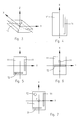
- the transducer described which was used in the first-generation ARVA apparatuses, is schematically shown by reference T1 in fig. 4; it constitutes a selective antenna capable of detecting the VCM_X component only, and namely the component in the X direction of the Magnetic Field Vector VCM, it being decided to adopt a spatial reference system consisting of the three Cartesian axes X, Y, Z, referred to with the outer casing 11 of the ARVA, as shown in fig. 3.
- the operator engaged in searching for a people buried under the snow, is entrusted with the task of systematically pointing the instrument in all the directions of the air space to search the strongest signal, which represents VCM in intensity and direction.
- Fig. 5 shows the embodiment of a second-generation of ARVA, in which two mono-axial transducers T1 and T2 have a typical L-shaped disposition according to X and Y axes of the triad of reference axes of fig. 3.
- fig. 6 shows a cross-shaped disposition of the two mono-axial transducers T1 and T2, also of a second-generation of ARVA, whose cores are distinct and separate from each other, likewise to the previous embodiments.
- fig. 7 shows the disposition of three mono-axial transducers T1, T2 and T3 existing in third-generation types of ARVA.
- the addition of a third mono-axial transducer T3, parallel to the axis Z, enables the calculation of the vector VCM of the magnetic field as a product of VCM_X, VCM_Y and VCM_Z vectors; consequently in this case the operator is relieved of the difficult and time-wasting task of finding the strongest signal by trials and errors.
- the conventional transducers of the bi-axial and tri-axial type obtained by simply combining two or three mono-axial transducers, suffer by at least two rather serious drawbacks.
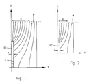
- fig. 2 With fig. 1, as previously mentioned, it can be seen that the effect of concentration of the flux, in the short bar 10' of fig. 2, is decisively smaller than the long bar 10 of fig. 1.
- FAF value Flux Aggregation Factor
- the second drawback comes from the lack of symmetry, with respect to the XZ and YZ planes, of the L-shaped disposition of the mono-axial transducers T1, T2 oriented according the X and Y axes of figures 5 and 7. If the distance which separates the magnetic bars of the two transducers T1 and T2 is not wide enough (in practice, so as not to increase the overall dimensions, it is generally not more than 10-15mm), the following operative anomalies occur:
- the main object of the invention is to provide a multi-axial magneto-electric transducer comprising an integrated system of directional antennas, capable of generating electromotive forces whose intensities are proportional to the components, according to the axes of a Cartesian system of reference, of a variable magnetic field which is propagated in the air space, and to comply with the following requirements as far as possible:
- a magneto-electric transducer comprising an integrated system or assembly of directional antennas according to claim 1.
- a multi-axial magneto-electric transducer for variable magnetic fields propagating in the space, comprising an assembly of directional antennas oriented according to Cartesian reference axes, in which each antenna comprises a core member of magnetically conductive material, having high magnetic permeability, for concentration or thickening of the flux, and an electric winding oriented according to a Cartesian reference axis, characterised by comprising an integrated core assembly, in which:
- the core members of the antennas are disposed symmetrically with respect to at least one reference plane passing through at least one of the Cartesian reference axes.
- the magneto-electric transducer is characterised in that at least one first antenna of the assembly comprises a plurality of antenna elements each having an elongated core portion oriented in the direction of a Cartesian reference axis; said core portion of each antenna element being disposed in magnetic continuity with the core member of a second antenna; said core portion being conformed and arranged to contribute to the flux thickening in the core member of the second antenna; and in that the electric winding of said first antenna comprises one or more winding sections coaxially disposed to respective core portions oriented according to said Cartesian axis of reference.
- the core members of the individual antennas define an integrated core assembly, in which various core portions of the individual antennas are disposed according to a ring-like, cross-like, double T-like, cubic cage-like, and parallelepiped-like shaped structure, or other suitable disposition.
- the disposition of the core members, or core portions of the integrated antenna assembly must be symmetrical with respect to one or more reference planes passing through the Cartesian reference axes.
- distality in continuity of the core members or the core portions of the antennas is understood to mean a “magnetic continuity” in which the core members or the core portions are physically in contact with one another, providing, at the most, slight structural, or even functional magnetic air gaps for the purpose of limiting certain problems deriving from possible unavoidable manufacturing defects.
- This invention is based on a particular integrated structure of the core members of directional antenna assembly for a multi-axial magneto-electric transducer which combines two expedients:
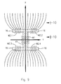
- FIG. 9 and 10 show the case of a double T-shaped integrated core structure or assembly for a bi-axial magneto-electric transducer.
- Figures 9 and 10 purely by way of example, indicate the paths of the flux ⁇ X of X direction, in the XY and respectively ZX planes of a Cartesian reference axes system.
- reference number 15 has been used to indicate a central core member, of magnetically conductive material
- reference number 16 has been used to indicate four side core members of the same material, disposed on both sides, at the ends of the central core member 15.
- reference W1 has been used to indicate the winding linked with the flux of X direction which flows along the flux collecting tube comprising the core member 15
- references W2.1, W2.2, W2.3 and W2.4 have been used to indicate the four winding sections of the winding linked with the flux of Y direction (not shown) which flows along a respective flux collecting tube comprising the core members 16, in a magneto-electric transducer TME characterised by a bi-axial antenna assembly.
- the core members 16 of Y direction are in magnetic continuity with the core member 15 of X direction, thereby significantly contributing to drainage of the ⁇ X flux, and to its concentration in the core member 15.
- the cross core members 16 are positioned in correspondence with the ends of the central core member 15, maintaining a symmetrical disposition with respect to a reference plane passing through the X axis; however, the core members 16 relating to the antenna of Y direction could also be arranged in a more or less backward position with respect to the ends of the central core member 15.
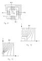
- a first preferential embodiment is obtained by using an annular structure for the core of a bi-axial X-Y TME, in particular the square ring-shaped structure 20 of fig. 11.
- references W3.1 and W3.2 have been used to indicate the winding sections of winding W3 relating to the antenna AX of X direction
- references W4.1 and W4.2 have been used to indicate the two winding sections of winding W4 of the antenna AY of Y direction
- the winding sections W3.1, W3.2 and W4.1, W4.2 of each antenna should be wound and connected in series to one another in such a way that the electromotive forces, induced by the linked magnetic fluxes of X and Y directions, are in phase with one another.
- the symmetry of the windings must be considered in the electrical sense, as non-geometrical: that is to say, the X flux, to be understood as direct like the axis X, must induce in the winding sections W3.1 and W3.2, symmetrical electromotive forces with respect to the XZ plane, and likewise for the Y flux, on the basis of the following:
- Fig. 11 shows a square ring-shaped structure of the core 20; it is obvious however that the same remarks could be made for a "rectangular ring-shaped" structure, or of any other suitable shape.
- the properties of the bi-axial TME having the square ring-shaped structure of fig. 11, can all be found, properly extended, in a most complex reticulated structure of any suitable geometrical shape, for example the cubic shape of Fig. 14, or a parallelepiped shape, that can be adopted for a tri-axial TME.
- the cubic cage-shaped structure of the integrated core assembly of fig. 14 consists of a frame of ferrite, or other magnetically conductive material, comprising a plurality of bars members 21, 22, 23 oriented according to X, Y and Z reference axes, disposed according to the edges of an ideal cube.
- Each winding of AX, AY and AZ antennas is composed of four winding sections WX 1,2,3,4 , WY 1,2,3,4 and WZ 1,2,3,4 , which must be connected in series with one another in such a way that the electromotive forces induced by the respective fluxes of X, Y and Z direction, are concordant with one another, as mentioned previously.
- a first solution is shown in fig. 15 which differs from the preceding solutions due to the fact that the winding of antenna AZ in this case is composed of only two winding sections W'Z1 and W'Z2 each of which is wound around a pair of bars 23 oriented according to the Z axis and positioned on a same face of the cube.
- a second solution is shown in fig. 16; in this case the antenna AZ is provided by a single winding section W'Z3 wound directly around the four bars 23 of the cubic cage, parallel oriented to the reference axis Z.
- the tri-axial cubic cage TME is unlikely to fit into a container of limited dimensions, for example in a rather flat container, such as for example the container of an ARVA apparatus. Consequently, it is possible to compress or reduce one of the dimensions. Assuming, for example, to reduce the dimension directed as the axis Z of a cubic cage whose bars have an L-shaped cross section, as shown for example in fig. 17, until the two square rings of the two opposite faces join overlapping together, parallel to the plane XY as shown in fig.18; a square ring-shaped magnetic structure is thereby obtained, having a "C"-shaped cross-section, with an internal groove.
- This structure involves antenna windings by two sections WX 1,2 and WY 1,2 , only instead of four, for the antennas AX and AY, and by a single section W'Z3 for the antenna AZ.
- the Flux Aggregation Factor FAF concerning the axis Z, in this case is reduced to a few units, but this is balanced by the larger amplitude of the surface impinged by the flux.
- Fig. 19 shows a simplification of the ring-shaped structure of the core assembly of fig. 18, which in this case has a simple "I"-shaped cross section.
- the ferrite ring can be divided into four portions, separated by respective magnetic air gaps in a range of about one millimetre or less, so as not to cause a flux leakage, and therefore granting a substantial magnetic continuity of the ring-shaped structure; the magnetic air gaps, disposed in such a way as to safeguard the symmetry of the ring, with respect to the coordinates defined by the Cartesian axes of reference, have the purpose of reducing the internal fluxes and the related inductances.
- the winding turns are maintained spaced apart from the core members of the transducer, for the dual purpose of not subjecting the windings (the ends of which are normally fastened to the casing), to the elastic movements of the core itself, and of reducing the capacitive couplings, through the core, both between the turns of the same circuit, thereby reducing leakages in the coil, as well as between the turns of separate circuits, thereby reducing the risk of interferences.
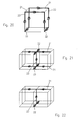
- Fig. 20 schematically shows an "offset square ring" or “three-dimensional” embodiment, in which several reference numbers of fig. 14 have been used to indicate similar or equivalent parts.
- the structure of the core of fig. 20 comprises two C-shaped dispositions of bars 21 and 23, relating to the axes Y and Z, on two parallel sides of an imaginary reference cube, in which the four bars 23 of the axis Z at one of their ends are connected by the bars 22 relating to the axis X.
- the solution of fig. 20 offers the advantage of reducing the number of the bars or of the structural elements which make up the entire integrated core assembly, with a consequent reduction in the weights and the costs.
- the symmetry with respect to the XY plane is lost, however the drawbacks resulting from the lack of symmetry can be compensated for and made acceptable if the dimension of the composite core, in the direction of the axis Z, is considerably smaller than the dimensions relating to the other two directions X and Y.
- Fig. 21 is a double cross-shaped solution, also for a tri-axial transducer, which can be derived from four juxtaposed cubic cages. In practice, it comprises a first upper core portion and a second lower core portion, both in the form of a cross, whose bars 21 and 22 are oriented according to the axes X and Y, and in which the nodes at the centre of the two crosses are connected by a central magnetic bar 23 oriented according to the axis Z.
- Fig. 22 shows a double offset T-shaped, or three-dimensional solution, in which the bars 21, 22 are oriented according to the axes X, Y, while the bar 23 is directed according to the axis Z of the antenna assembly; this solution makes it possible to considerably reduce the number of bars or elements which make up the composite structure of the core of a tri-axial transducer.
- core structures are possible; for example by crossing two double T-shaped structures of fig. 9, it is possible to obtain a double T-shaped structure according to the axes X and Y for a bi-axial transducer; it is also possible to obtain a triple double T-shaped structure by placing three double T-shaped structures according to the three axes X, Y and Z, in which the various core members are joined in a central node.
- a multi-axial magneto-electric transducer can be provided, for variable magnetic fields which propagate in the space, characterised by particular conformations and dispositions of the core members of the antenna system or assembly.
- the square ring-shaped core of fig. 11 could have a rectangular, circular or other suitable annular shape; the profile of the cross section could be of any type, for example a square, rectangular, polygonal, elliptic or circular-shaped closed profile.
- the groove could be on the inner side or on the outer side, or on both sides in the case of an "H"-shaped profile, with the depth of the grooves being identical to or differing from one another.
Landscapes
- Physics & Mathematics (AREA)
- Engineering & Computer Science (AREA)
- Acoustics & Sound (AREA)
- Signal Processing (AREA)
- Variable-Direction Aerials And Aerial Arrays (AREA)
Applications Claiming Priority (1)
| Application Number | Priority Date | Filing Date | Title |
|---|---|---|---|
| ITMI20051540 ITMI20051540A1 (it) | 2005-08-05 | 2005-08-05 | Trasduttore magneto-elettrico multiasse per capi magnetici variabili |
Publications (1)
| Publication Number | Publication Date |
|---|---|
| EP1750478A2 true EP1750478A2 (fr) | 2007-02-07 |
Family
ID=37206878
Family Applications (1)
| Application Number | Title | Priority Date | Filing Date |
|---|---|---|---|
| EP20060012504 Withdrawn EP1750478A2 (fr) | 2005-08-05 | 2006-06-19 | Transducteur magnéto-électrique multi-axiale pour champs magnétiques variables |
Country Status (2)
| Country | Link |
|---|---|
| EP (1) | EP1750478A2 (fr) |
| IT (1) | ITMI20051540A1 (fr) |
-
2005
- 2005-08-05 IT ITMI20051540 patent/ITMI20051540A1/it unknown
-
2006
- 2006-06-19 EP EP20060012504 patent/EP1750478A2/fr not_active Withdrawn
Also Published As
| Publication number | Publication date |
|---|---|
| ITMI20051540A1 (it) | 2007-02-06 |
Similar Documents
| Publication | Publication Date | Title |
|---|---|---|
| JP4505338B2 (ja) | 無線周波数磁界を感知する素子 | |
| JP4212125B2 (ja) | 保証質量支持システム | |
| FI73320C (fi) | Nmr-spolarrangemang. | |
| EP1048958A2 (fr) | Capteur magnétique et son procédé de fabrication | |
| JPH0617896B2 (ja) | 誘導性センサ装置および同装置使用のための測定装置 | |
| US20050127914A1 (en) | Magnetic resonance antenna | |
| BR102017010197A2 (pt) | Aparelho de detecção de metais | |
| US20110136444A1 (en) | Transmit and receive antenna | |
| EP1281092B1 (fr) | Appareil de resonance magnetique comprenant une structure guidant le flux magnetique rf | |
| US6014111A (en) | Ferrite crossed-loop antenna of optimal geometry and construction and method of forming same | |
| US3898565A (en) | Magnetic wave communication system | |
| Purcell | Helmholtz coils revisited | |
| US4929881A (en) | Probe for nuclear magnetic resonance apparatus | |
| JP3110115B2 (ja) | 磁気共鳴イメージング装置 | |
| US20110215808A1 (en) | Passive underground electronic marker for use in any orientation | |
| US4486731A (en) | Coil assembly with flux directing means | |
| US6265871B1 (en) | Device for generating eddy current induction and detection by means of the axes of permeability within a toroid/torus core | |
| JPH07324935A (ja) | 地磁気方位センサ及びその製造方法 | |
| US20220299674A1 (en) | Superconducting gravity gradiometer and sensitivity improvement method thereof | |
| JP2726218B2 (ja) | 3次元磁界検出コイル | |
| JPH03202703A (ja) | インダクタンス形変位センサ | |
| US4249129A (en) | Efficient simultaneous electromagnetic transmission or reception at different frequencies in electromagnetic mapping | |
| KR102125553B1 (ko) | 알에프 코일 및 이를 포함하고 있는 알에프 코일 어셈블리 | |
| RU2630716C2 (ru) | Комбинированный магниторезистивный датчик | |
| CN116224182B (zh) | 超导二阶梯度线圈结构、制造方法及超导量子干涉梯度计 |
Legal Events
| Date | Code | Title | Description |
|---|---|---|---|
| PUAI | Public reference made under article 153(3) epc to a published international application that has entered the european phase |
Free format text: ORIGINAL CODE: 0009012 |
|
| AK | Designated contracting states |
Kind code of ref document: A2 Designated state(s): AT BE BG CH CY CZ DE DK EE ES FI FR GB GR HU IE IS IT LI LT LU LV MC NL PL PT RO SE SI SK TR |
|
| AX | Request for extension of the european patent |
Extension state: AL BA HR MK YU |
|
| STAA | Information on the status of an ep patent application or granted ep patent |
Free format text: STATUS: THE APPLICATION IS DEEMED TO BE WITHDRAWN |
|
| 18D | Application deemed to be withdrawn |
Effective date: 20101231 |