EP1750921B1 - Verfahren zur herstellung eines ballistischen schutzpanzers - Google Patents
Verfahren zur herstellung eines ballistischen schutzpanzers Download PDFInfo
- Publication number
- EP1750921B1 EP1750921B1 EP05707204A EP05707204A EP1750921B1 EP 1750921 B1 EP1750921 B1 EP 1750921B1 EP 05707204 A EP05707204 A EP 05707204A EP 05707204 A EP05707204 A EP 05707204A EP 1750921 B1 EP1750921 B1 EP 1750921B1
- Authority
- EP
- European Patent Office
- Prior art keywords
- preform
- pressing operation
- textile layers
- hot
- textile
- Prior art date
- Legal status (The legal status is an assumption and is not a legal conclusion. Google has not performed a legal analysis and makes no representation as to the accuracy of the status listed.)
- Expired - Lifetime
Links
- 230000001681 protective effect Effects 0.000 title claims abstract description 35
- 238000004519 manufacturing process Methods 0.000 title claims abstract description 11
- 239000004753 textile Substances 0.000 claims abstract description 64
- 238000000034 method Methods 0.000 claims abstract description 40
- 238000003825 pressing Methods 0.000 claims abstract description 31
- 238000009958 sewing Methods 0.000 claims abstract description 19
- 239000010410 layer Substances 0.000 claims description 87
- 238000007731 hot pressing Methods 0.000 claims description 19
- 239000011241 protective layer Substances 0.000 claims description 12
- 239000011347 resin Substances 0.000 claims description 10
- 229920005989 resin Polymers 0.000 claims description 10
- 239000000853 adhesive Substances 0.000 claims description 6
- 230000001070 adhesive effect Effects 0.000 claims description 6
- 239000000463 material Substances 0.000 claims description 6
- 239000004033 plastic Substances 0.000 claims description 6
- 229920003023 plastic Polymers 0.000 claims description 6
- 239000007795 chemical reaction product Substances 0.000 claims description 3
- 239000011159 matrix material Substances 0.000 claims description 2
- 238000010438 heat treatment Methods 0.000 claims 2
- 239000012467 final product Substances 0.000 abstract description 7
- 239000004744 fabric Substances 0.000 description 19
- 239000007767 bonding agent Substances 0.000 description 9
- 239000000835 fiber Substances 0.000 description 5
- 230000006378 damage Effects 0.000 description 4
- 230000000694 effects Effects 0.000 description 3
- 238000003475 lamination Methods 0.000 description 3
- 230000000149 penetrating effect Effects 0.000 description 3
- 239000004705 High-molecular-weight polyethylene Substances 0.000 description 2
- 206010041662 Splinter Diseases 0.000 description 2
- 239000004760 aramid Substances 0.000 description 2
- 229920003235 aromatic polyamide Polymers 0.000 description 2
- 239000011248 coating agent Substances 0.000 description 2
- 238000000576 coating method Methods 0.000 description 2
- 230000032798 delamination Effects 0.000 description 2
- 230000001771 impaired effect Effects 0.000 description 2
- 208000014674 injury Diseases 0.000 description 2
- 239000013067 intermediate product Substances 0.000 description 2
- 238000002360 preparation method Methods 0.000 description 2
- 206010019196 Head injury Diseases 0.000 description 1
- 208000027418 Wounds and injury Diseases 0.000 description 1
- 230000006978 adaptation Effects 0.000 description 1
- 239000000654 additive Substances 0.000 description 1
- 230000000996 additive effect Effects 0.000 description 1
- 238000005452 bending Methods 0.000 description 1
- 230000015572 biosynthetic process Effects 0.000 description 1
- 230000037237 body shape Effects 0.000 description 1
- 230000000295 complement effect Effects 0.000 description 1
- 230000001419 dependent effect Effects 0.000 description 1
- 238000010586 diagram Methods 0.000 description 1
- 238000009499 grossing Methods 0.000 description 1
- 230000003116 impacting effect Effects 0.000 description 1
- 239000003973 paint Substances 0.000 description 1
- 239000000047 product Substances 0.000 description 1
- 230000002787 reinforcement Effects 0.000 description 1
- 230000000717 retained effect Effects 0.000 description 1
- 238000000926 separation method Methods 0.000 description 1
- 239000007858 starting material Substances 0.000 description 1
- 230000008733 trauma Effects 0.000 description 1
Images




Classifications
-
- B—PERFORMING OPERATIONS; TRANSPORTING
- B32—LAYERED PRODUCTS
- B32B—LAYERED PRODUCTS, i.e. PRODUCTS BUILT-UP OF STRATA OF FLAT OR NON-FLAT, e.g. CELLULAR OR HONEYCOMB, FORM
- B32B5/00—Layered products characterised by the non- homogeneity or physical structure, i.e. comprising a fibrous, filamentary, particulate or foam layer; Layered products characterised by having a layer differing constitutionally or physically in different parts
- B32B5/22—Layered products characterised by the non- homogeneity or physical structure, i.e. comprising a fibrous, filamentary, particulate or foam layer; Layered products characterised by having a layer differing constitutionally or physically in different parts characterised by the presence of two or more layers which are next to each other and are fibrous, filamentary, formed of particles or foamed
- B32B5/24—Layered products characterised by the non- homogeneity or physical structure, i.e. comprising a fibrous, filamentary, particulate or foam layer; Layered products characterised by having a layer differing constitutionally or physically in different parts characterised by the presence of two or more layers which are next to each other and are fibrous, filamentary, formed of particles or foamed one layer being a fibrous or filamentary layer
- B32B5/26—Layered products characterised by the non- homogeneity or physical structure, i.e. comprising a fibrous, filamentary, particulate or foam layer; Layered products characterised by having a layer differing constitutionally or physically in different parts characterised by the presence of two or more layers which are next to each other and are fibrous, filamentary, formed of particles or foamed one layer being a fibrous or filamentary layer another layer next to it also being fibrous or filamentary
-
- B—PERFORMING OPERATIONS; TRANSPORTING
- B29—WORKING OF PLASTICS; WORKING OF SUBSTANCES IN A PLASTIC STATE IN GENERAL
- B29C—SHAPING OR JOINING OF PLASTICS; SHAPING OF MATERIAL IN A PLASTIC STATE, NOT OTHERWISE PROVIDED FOR; AFTER-TREATMENT OF THE SHAPED PRODUCTS, e.g. REPAIRING
- B29C43/00—Compression moulding, i.e. applying external pressure to flow the moulding material; Apparatus therefor
- B29C43/02—Compression moulding, i.e. applying external pressure to flow the moulding material; Apparatus therefor of articles of definite length, i.e. discrete articles
- B29C43/14—Compression moulding, i.e. applying external pressure to flow the moulding material; Apparatus therefor of articles of definite length, i.e. discrete articles in several steps
- B29C43/146—Compression moulding, i.e. applying external pressure to flow the moulding material; Apparatus therefor of articles of definite length, i.e. discrete articles in several steps for making multilayered articles
-
- B—PERFORMING OPERATIONS; TRANSPORTING
- B29—WORKING OF PLASTICS; WORKING OF SUBSTANCES IN A PLASTIC STATE IN GENERAL
- B29C—SHAPING OR JOINING OF PLASTICS; SHAPING OF MATERIAL IN A PLASTIC STATE, NOT OTHERWISE PROVIDED FOR; AFTER-TREATMENT OF THE SHAPED PRODUCTS, e.g. REPAIRING
- B29C70/00—Shaping composites, i.e. plastics material comprising reinforcements, fillers or preformed parts, e.g. inserts
- B29C70/04—Shaping composites, i.e. plastics material comprising reinforcements, fillers or preformed parts, e.g. inserts comprising reinforcements only, e.g. self-reinforcing plastics
- B29C70/28—Shaping operations therefor
- B29C70/40—Shaping or impregnating by compression not applied
- B29C70/42—Shaping or impregnating by compression not applied for producing articles of definite length, i.e. discrete articles
- B29C70/46—Shaping or impregnating by compression not applied for producing articles of definite length, i.e. discrete articles using matched moulds, e.g. for deforming sheet moulding compounds [SMC] or prepregs
- B29C70/465—Shaping or impregnating by compression not applied for producing articles of definite length, i.e. discrete articles using matched moulds, e.g. for deforming sheet moulding compounds [SMC] or prepregs and impregnating by melting a solid material, e.g. sheets, powders of fibres
-
- B—PERFORMING OPERATIONS; TRANSPORTING
- B32—LAYERED PRODUCTS
- B32B—LAYERED PRODUCTS, i.e. PRODUCTS BUILT-UP OF STRATA OF FLAT OR NON-FLAT, e.g. CELLULAR OR HONEYCOMB, FORM
- B32B5/00—Layered products characterised by the non- homogeneity or physical structure, i.e. comprising a fibrous, filamentary, particulate or foam layer; Layered products characterised by having a layer differing constitutionally or physically in different parts
- B32B5/02—Layered products characterised by the non- homogeneity or physical structure, i.e. comprising a fibrous, filamentary, particulate or foam layer; Layered products characterised by having a layer differing constitutionally or physically in different parts characterised by structural features of a fibrous or filamentary layer
- B32B5/06—Layered products characterised by the non- homogeneity or physical structure, i.e. comprising a fibrous, filamentary, particulate or foam layer; Layered products characterised by having a layer differing constitutionally or physically in different parts characterised by structural features of a fibrous or filamentary layer characterised by a fibrous or filamentary layer mechanically connected, e.g. by needling to another layer, e.g. of fibres, of paper
-
- B—PERFORMING OPERATIONS; TRANSPORTING
- B29—WORKING OF PLASTICS; WORKING OF SUBSTANCES IN A PLASTIC STATE IN GENERAL
- B29L—INDEXING SCHEME ASSOCIATED WITH SUBCLASS B29C, RELATING TO PARTICULAR ARTICLES
- B29L2031/00—Other particular articles
- B29L2031/48—Wearing apparel
- B29L2031/4807—Headwear
- B29L2031/4814—Hats
- B29L2031/4821—Helmets
-
- B—PERFORMING OPERATIONS; TRANSPORTING
- B29—WORKING OF PLASTICS; WORKING OF SUBSTANCES IN A PLASTIC STATE IN GENERAL
- B29L—INDEXING SCHEME ASSOCIATED WITH SUBCLASS B29C, RELATING TO PARTICULAR ARTICLES
- B29L2031/00—Other particular articles
- B29L2031/768—Protective equipment
-
- B—PERFORMING OPERATIONS; TRANSPORTING
- B32—LAYERED PRODUCTS
- B32B—LAYERED PRODUCTS, i.e. PRODUCTS BUILT-UP OF STRATA OF FLAT OR NON-FLAT, e.g. CELLULAR OR HONEYCOMB, FORM
- B32B2250/00—Layers arrangement
- B32B2250/20—All layers being fibrous or filamentary
-
- B—PERFORMING OPERATIONS; TRANSPORTING
- B32—LAYERED PRODUCTS
- B32B—LAYERED PRODUCTS, i.e. PRODUCTS BUILT-UP OF STRATA OF FLAT OR NON-FLAT, e.g. CELLULAR OR HONEYCOMB, FORM
- B32B2260/00—Layered product comprising an impregnated, embedded, or bonded layer wherein the layer comprises an impregnation, embedding, or binder material
- B32B2260/02—Composition of the impregnated, bonded or embedded layer
- B32B2260/021—Fibrous or filamentary layer
- B32B2260/023—Two or more layers
-
- B—PERFORMING OPERATIONS; TRANSPORTING
- B32—LAYERED PRODUCTS
- B32B—LAYERED PRODUCTS, i.e. PRODUCTS BUILT-UP OF STRATA OF FLAT OR NON-FLAT, e.g. CELLULAR OR HONEYCOMB, FORM
- B32B2260/00—Layered product comprising an impregnated, embedded, or bonded layer wherein the layer comprises an impregnation, embedding, or binder material
- B32B2260/04—Impregnation, embedding, or binder material
- B32B2260/046—Synthetic resin
-
- B—PERFORMING OPERATIONS; TRANSPORTING
- B32—LAYERED PRODUCTS
- B32B—LAYERED PRODUCTS, i.e. PRODUCTS BUILT-UP OF STRATA OF FLAT OR NON-FLAT, e.g. CELLULAR OR HONEYCOMB, FORM
- B32B2262/00—Composition or structural features of fibres which form a fibrous or filamentary layer or are present as additives
- B32B2262/02—Synthetic macromolecular fibres
- B32B2262/0253—Polyolefin fibres
-
- B—PERFORMING OPERATIONS; TRANSPORTING
- B32—LAYERED PRODUCTS
- B32B—LAYERED PRODUCTS, i.e. PRODUCTS BUILT-UP OF STRATA OF FLAT OR NON-FLAT, e.g. CELLULAR OR HONEYCOMB, FORM
- B32B2262/00—Composition or structural features of fibres which form a fibrous or filamentary layer or are present as additives
- B32B2262/02—Synthetic macromolecular fibres
- B32B2262/0261—Polyamide fibres
- B32B2262/0269—Aromatic polyamide fibres
-
- B—PERFORMING OPERATIONS; TRANSPORTING
- B32—LAYERED PRODUCTS
- B32B—LAYERED PRODUCTS, i.e. PRODUCTS BUILT-UP OF STRATA OF FLAT OR NON-FLAT, e.g. CELLULAR OR HONEYCOMB, FORM
- B32B2307/00—Properties of the layers or laminate
- B32B2307/50—Properties of the layers or laminate having particular mechanical properties
- B32B2307/51—Elastic
-
- B—PERFORMING OPERATIONS; TRANSPORTING
- B32—LAYERED PRODUCTS
- B32B—LAYERED PRODUCTS, i.e. PRODUCTS BUILT-UP OF STRATA OF FLAT OR NON-FLAT, e.g. CELLULAR OR HONEYCOMB, FORM
- B32B2307/00—Properties of the layers or laminate
- B32B2307/50—Properties of the layers or laminate having particular mechanical properties
- B32B2307/542—Shear strength
-
- B—PERFORMING OPERATIONS; TRANSPORTING
- B32—LAYERED PRODUCTS
- B32B—LAYERED PRODUCTS, i.e. PRODUCTS BUILT-UP OF STRATA OF FLAT OR NON-FLAT, e.g. CELLULAR OR HONEYCOMB, FORM
- B32B2437/00—Clothing
- B32B2437/04—Caps, helmets
-
- B—PERFORMING OPERATIONS; TRANSPORTING
- B32—LAYERED PRODUCTS
- B32B—LAYERED PRODUCTS, i.e. PRODUCTS BUILT-UP OF STRATA OF FLAT OR NON-FLAT, e.g. CELLULAR OR HONEYCOMB, FORM
- B32B2571/00—Protective equipment
- B32B2571/02—Protective equipment defensive, e.g. armour plates or anti-ballistic clothing
-
- Y—GENERAL TAGGING OF NEW TECHNOLOGICAL DEVELOPMENTS; GENERAL TAGGING OF CROSS-SECTIONAL TECHNOLOGIES SPANNING OVER SEVERAL SECTIONS OF THE IPC; TECHNICAL SUBJECTS COVERED BY FORMER USPC CROSS-REFERENCE ART COLLECTIONS [XRACs] AND DIGESTS
- Y10—TECHNICAL SUBJECTS COVERED BY FORMER USPC
- Y10T—TECHNICAL SUBJECTS COVERED BY FORMER US CLASSIFICATION
- Y10T156/00—Adhesive bonding and miscellaneous chemical manufacture
- Y10T156/10—Methods of surface bonding and/or assembly therefor
- Y10T156/1002—Methods of surface bonding and/or assembly therefor with permanent bending or reshaping or surface deformation of self sustaining lamina
- Y10T156/1028—Methods of surface bonding and/or assembly therefor with permanent bending or reshaping or surface deformation of self sustaining lamina by bending, drawing or stretch forming sheet to assume shape of configured lamina while in contact therewith
Definitions
- the present invention relates to a method for producing a ballistic protective armor according to the preamble of claim 1.
- Ballistic protective armor are known in various embodiments as part of ballistic protective clothing, such as military helmets for protection against projectile impacts and shrapnel, as splinter protection vests and the like.
- To produce a protective armor of the type present here first individual textile layers of a high-strength technical fabric are laid one on top of the other, so that a layer structure is produced. After the manufacturing process, that in the document US-A-4,199.388 is disclosed, the textile layers of this layered layer are pre-pressed into a preform, which is then hot pressed at a higher temperature, so that a laminate is formed.
- US-A-3,841,954 a protective armor, in which the textile layers of the layered fabric are sewn together and then subjected to a pressing operation.
- the protective armor shown there serves as a back reinforcement of another armor layer, so that a high resistance to splinter impact is created.
- the ballistic protective armor must be well adapted to the body shape of the wearer. It is therefore desirable to be able to produce the tanks in the widest possible variety of shapes.
- this is not always a problem, since in a subsequent bending, upsetting, deep drawing or the like, the internal structure of the relatively rigid textile laminate is changed in such a way that the protective effect can be affected in whole or in places.
- a coating applied to the textile layers for formation of the laminate penetrates too far into the fibers, since the fabric of the textile layers and the yarn of the seams must retain defined properties with regard to elasticity and tensile strength.
- the in US 3,841,954 Although disclosed protective armor after sewing and presses to some extent flexible, but can not be spherical, ie deform to a hemisphere, for example. Thus, no helmet shells can be produced.
- Object of the present invention is therefore to provide a method for producing a ballistic protective armor of the type mentioned, which makes it possible to produce protective armor in a wider variety of spatial forms, as it was previously possible according to the known prior art, without the Protective properties are impaired.
- the textile layers of the layered fabric are pre-pressed before sewing into a preform whose spatial form already corresponds to the end product to be produced, that is, for example, the desired calotte shape. Subsequently, the textile layers of this pre-pressed Sewn preform together.
- the processing is completed by a hot pressing operation performed at a higher temperature than in the pre-pressing to produce the preform. While the pre-pressing operation essentially serves to impart the desired shape to the layer covering before the sewing step, the layers are finally compacted during the hot pressing so that the desired laminate is produced with high strength. As a result, the produced ballistic protective armor also achieved its structural strength.
- An advantage of the method according to the invention is that the shape of the final product already exists prior to sewing and that the final hot pressing no longer significantly changes the product shape.
- the preform is no longer bent or compressed after sewing so that it retains its structure during hot pressing. Therefore, the fabric structure of the textile layers is maintained as well as the elongation properties of the yarn used for sewing, so that its tensile strength and elasticity remain sufficient to largely ensure the cohesion of the laminate upon impact of a projectile in the armor.
- a spherically curved ballistic protective armor which is to serve as a helmet shell of a ballistic protective helmet.
- textile layers which are woven from a high-strength yarn or technical fibers such as aramid, high molecular weight polyethylene or the like and at least one side with a bonding agent such as resin, plastic or adhesive are laminated.
- a resin film which, when heated, conforms to the surface of the fabric without penetrating the fibers.
- a laminate connection of the textile layers is formed with each other by the bonding agent partially penetrates into the textile layers, but only so far that the elasticity and mobility of the fabric fibers are retained.
- the textile layers can absorb to some extent the kinetic energy of a penetrating projectile.
- a preparation step of the method according to the invention can accordingly consist in the preparation of individual textile layer blanks by the previously described lamination with a bonding agent such as resin, plastic or adhesive.
- the blanks of the textile layers are first in a in Fig. 1 10 is laid on each other in a predetermined order.
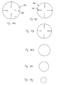
- the layers are provided with radial cuts, which allow the situation by overlapping surface areas to give a curved shape and thus to allow further processing to an approximately spherical shape.
- the process of layering 10 can be made into a layer structure in a form which also serves as a preheating mold. Since the number of textile layers used can be very large, it may prove helpful to fix the layer covering, for example, by brackets on the edge of the preheating mold.
- the textile layers are heated and nestle against each other and onto the surface of the fabric Preheating mold 110, which may advantageously already have approximately the shape of the final product to be produced.
- the layer layer is pre-pressed cold in a pre-pressing process 30, so that a preform is formed whose spatial form already corresponds to the end product to be produced.
- the textile layers of this preform can be fixed point by point by staples or the like after the pre-pressing operation 30 (step 40), so that their cohesion is guaranteed.
- the textile layers of the preform are sewn together (step 50). Suturing may be followed by an intermediate squeezing operation 60 after which further sutures may be applied to reinforce critical zones of the ballistic protective armor (step 70).
- an additional intermediate pressing operation 80 the now completely sewn preform can be provided on its inside and / or outside with a protective layer (step 90).
- the stitched preform is pressed together with its protective layers in a hot pressing process 100, so that the textile layers are joined by the bonding agent applied to them to form a laminate.
- the ballistic protective helmet produced in this way is held together on the one hand by the laminate connection of the textile layers with one another and on the other hand additionally by the seams attached during sewing 50, 70.
- Fig. 2 schematically shows a section through a preheating mold 110, the inner surface 112 is formed to receive a layered fabric 114 of textile layers hemispherical.
- the individual textile layers consist of high tensile strength yarns or fibers such as high molecular weight polyethylene, aramid or the like and have been laminated on one side in a pretreatment step with a bonding agent such as resin, plastic or adhesive.
- This textile sheet material usually has a certain stiffness, so that it is advantageously heated before further processing within the preheating mold 110.
- the in Fig. 1 designated 10 process step laying of the textile layers 116 in the preheating mold 110 itself.
- Radial cuts 118 in the ply cuts facilitate adaptation to the preheat mold 110.
- the ply coat 114 thus formed can be temporarily fixed in or on the mold so that the textile plies 116 do not move against each other.
- the textile layers 116 of the layered fabric 114 conform to the hemispherical inner surface 112, since the textile ply material and the stacked bonding agent heat up and the layers become flexible as a result.
- the preheating operation is preferably performed at a temperature of the preheating mold 110 of 60 ° C. In the ideal case, the individual textile layers 116 lie smoothly on one another after the step 20 of the preheating, so that the layer layer 114 assumes a hemispherical shape.
- Fig. 3 shows the laterally cut preheating mold 110, which contains the Schichtgelege 114, in a perspective view.
- the cold press 120 comprises a hemispherical lower mold half 122 on which the layer web 114 is placed with its hollow inside, and a hollow, also hemispherical upper mold half 124 which is intended to be lowered onto the lower mold half 122 in such a way it surrounds the outside of the layered fabric 114, as in Fig. 5 shown.
- the layered covering 114 is cold-pressed from textile layers 116 (method step 30 in FIG Fig. 1 ).
- pressing pressure and temperature are to be chosen so that an intermediate product with an already relatively compact sheet pack is formed, the layers of which do not readily solve by themselves from each other.
- the pre-pressing can be carried out, for example, at room temperature and at a pressure of 150 kg / cm 2 .
- the preform 130 produced by the pre-pressing process 30, which is in Fig. 6 is already shown, the shape of the ballistic protective armor to be produced, so in the present embodiment, the desired shape of the helmet shell. However, he does not receive his final protective properties until further process steps, which are explained below.
- the individual textile layers 116 of the preform 130 can be fixed in places to one another prior to further processing (method step 40 in FIG Fig. 1 ), such as by point attachment of connectors such as brackets or the like, which are injected at different locations in the layer structure 114. These connectors are in Fig. 6 not shown for clarity.
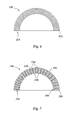
- the preform 130 from Fig. 6 is then sewn, as it is in Fig. 7 is shown schematically (process step 50 in Fig. 1 ).
- the preformed and possibly point-wise fixed preform 130 is provided with a sewing machine with seams which hold the individual textile layers 116 of the layered fabric 114 together.
- Fig. 1 the preformed and possibly point-wise fixed preform 130 is provided with a sewing machine with seams which hold the individual textile layers 116 of the layered fabric 114 together.
- a meandering seam 132 is shown extending in sections both on the inside and on the outside of the preform 130, and the inner and outer side portions 134 and 136 are joined by portions 138 of the seam 132 which are in radial direction of the hemisphere of the preform 130, that is, extend in the lamination direction and thus ensure the cohesion of the textile layers 116.
- the stitch pattern of the seam 132 is in Fig. 6 greatly simplified and can also be designed more complex. The sewing method can be adjusted as required to the required protective properties of the ballistic protective helmet to be produced.
- the yarn of the seam 132 should be selected to have high tensile strength but at the same time have some elasticity so that when a bullet hits the ply package 114 it will not shear off a large number of yarn sections 138 in the direction of lamination comes. It is advantageous if the yarn 132 can absorb a large portion of the projectile energy and stretch. A partial delamination of the inner textile layers 116 of the layer package 114 is hereby accepted to a certain extent.
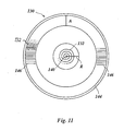
- the course of the seam 132 can be chosen so that the seam winds from the center of area 140 of the dome of the preform 130 spiraling around this center point 140 around to the edge 142 of the calotte, as it is complementary in Fig. 11 showing a plan view of the inner surface 144 of the preform 130. For clarity, only a portion of the helical path of suture 132 is shown, and it should be understood that suture 132 continues to the edge in the manner shown.
- the helical course of the seam 132 simplifies the processing since the preform 130 can thus easily be held in the sewing machine and be guided in it by a rotary movement.
- the radial distances of the seam 132 may vary here. Basically, the cohesion of the layered fabric 114 improves, the denser the seams are.
- the protective properties of the final product can be adjusted so that a sufficient perforation resistance is achieved and Detachment of the inner textile layers 116 of the layered layer 114, takes place by a penetrating projectile only to a small extent.
- the resin content of the layered fabric 114 is kept low to reduce the weight of the armor, the release effect of the inner layers 116 is promoted, but this can be compensated for by reducing the seam spacing.
- the seam 132 is thus an additive component that allows for a reduction in resin content without sacrificing the protective effect.
- the seam distance in the radial direction may be, for example, 6 mm, while outside of this area R it increases to 10 mm.
- the seam spacing can again decrease to 6 mm.
- the preform 130 may be subjected to an intermediate pressing operation (step 60 in FIG Fig. 1 ), which serves to give the layered layer 114 of the preform 130 an even stronger cohesion.
- step 60 additional seams 146 may be applied in certain areas of the preform 130, which intersect the helical seam 132 and reinforce particularly vulnerable areas of the ballistic protective helmet to be produced, such as the ear areas.
- a further intermediate pressing operation can be carried out (step 80). Accordingly, after each sewing 50,70 an intermediate pressing 60,80 can be performed.
- the outer protective layer 150 is a textile layer laminated on both sides with the connecting means, that is to say with resin, plastic or adhesive, of the same or similar material as the already sewn textile layers 116.
- This outer textile layer 150 is layered on the preform 130 while the opposite inner side 144 of the preform 130 is merely coated with the bonding agent with which the textile layers 116 and 150 are also coated.
- a layer 152 of resin, plastic, or adhesive is applied to the hemispherical inner surface 144 of the preform 130 and protects and fixes the inward portions 136 of the yarn 132 so that the preform 130 is protected from both surface sides and the yarn 132 in FIG Case of damage of the textile layered fabric 114 can not slide out sections of the stitch channels.
- This process step of applying protective layers 150, 152 is in Fig. 8 shown:
- the preform 130 provided with the protective layers 150 and 152 becomes one.
- the coated preform 130 is placed in a hot press 160 for this purpose, that is, the preform 130 is placed with its hollow inside on a corresponding lower mold half 162, while a hemispherical hollow upper mold half 164 is provided, perpendicular to the lower mold half 162nd to be lowered.
- Hot pressing (step 100 in Fig. 1 ) is preferably carried out at a temperature between 150 ° C and 175 ° C and at a pressure of 200 kg / cm 2 , that is, at higher pressure and temperature values than in the preceding pre- and intermediate pressing operations 30,60,80.
- the bonding agent coating of the individual textile layers 116 partially penetrates the fabric and forms a bonding matrix through which the textile layers 116 are bonded together to form a laminate.
- the laminate layer 114 of the preform 130 may be slightly compressed without changing the shape of the preform 130.
- the textile outer protective layer 150 and the inner protective layer 152 also become Components of this laminate and form a firm connection with the sewn layer layer 114 of the preform 130 a.
- the spherically curved shape of the preform 130 is not changed by the hot pressing 100. Therefore, there is also no risk that the layer structure of the layered fabric 114, which has already been determined by the pre-pressing 30 and stitching 50,70, is impaired. That is, the final shape of the final product to be produced is already created by the pre-pressing 30, that is, the production of the preform 130 and stitching 50,70 takes place on an intermediate product, which already has the desired spatial shape. This represents a significant advantage over known methods, in which the layer structure is first determined by sewing and then pre-pressing in the area and only then is a reshaping of the layered fabric made.
- the ballistic protective helmet can be taken as a final product and subjected to final processing steps, such as smoothing the edges, attaching an edge protection, a paint on the top, a suitable lining of the helmet shell and so on.
Landscapes
- Engineering & Computer Science (AREA)
- Mechanical Engineering (AREA)
- Chemical & Material Sciences (AREA)
- Composite Materials (AREA)
- Casting Or Compression Moulding Of Plastics Or The Like (AREA)
- Laminated Bodies (AREA)
- Aiming, Guidance, Guns With A Light Source, Armor, Camouflage, And Targets (AREA)
- Moulding By Coating Moulds (AREA)
- Cable Accessories (AREA)
- Apparatuses And Processes For Manufacturing Resistors (AREA)
- Manufacturing Cores, Coils, And Magnets (AREA)
- Filling Or Discharging Of Gas Storage Vessels (AREA)
Description
- Die vorliegende Erfindung betrifft ein Verfahren zur Herstellung eines ballistischen Schutzpanzers gemäß dem Oberbegriff des Anspruchs 1.
- Ballistische Schutzpanzer sind in unterschiedlichen Ausführungsformen als Bestandteil ballistischer Schutzkleidung bekannt, wie etwa als militärische Helme zum Schutz gegen Projektileinschläge und Granatsplitter, als Splitterschutzwesten und dergleichen mehr. Zur Herstellung eines Schutzpanzers der hier vorliegenden Art werden zunächst einzelne textile Lagen aus einem hochfesten technischen Gewebe aufeinander verlegt, so dass ein Schichtgelege entsteht. Nach dem Herstellungsverfahren, das in dem Dokument
US-A-4,199.388 offenbart ist, werden die textilen Lagen dieses Schichtgeleges zu einem Vorformling vorgepresst, der anschließend mit einer höheren Temperatur heißgepreßt wird, so dass ein Laminat entsteht. - Ferner offenbart die Patentschrift
US-A-3,841,954 einen Schutzpanzer, bei welchem die textilen Lagen des Schichtgeleges miteinander vernäht und anschließend einem Preßvorgang unterzogen werden. Der dort gezeigte Schutzpanzer dient als rückseitige Verstärkung einer weiteren Panzerungsschicht, so dass eine hohe Widerstandsfähigkeit gegenüber einem Splittereinschlag geschaffen wird. - Durch das Vernähen können die Dichte und Festigkeit des Schichtgeleges gesteigert werden, so dass die Schutzwirkung des Panzers verbessert wird. Darüber hinaus ist es bekannt, ballistische Schutzpanzer aus laminierten textilen Lagen herzustellen, die die Energie eines aufprallenden Projektils weitgehend absorbieren. Dies geschieht dadurch, dass das Projektil die äußeren Lagen des Laminats durchschlägt, sich hierbei verformt und durch die verbleibenden Lagen an der zu schützenden Innenseite des Panzers aufgefangen wird, da die kinetische Energie nach der Zerstörung der Außenlagen bereits stark verringert ist. Diese verbleibenden Fanglagen lösen sich von den durchschlagenen Außenlagen teilweise ab, so dass eine Ausbeulung zur Innenseite des Schutzpanzers hin entsteht, in der das Projektil verbleibt. Da ein übermäßiger Ausbeulungseffekt zu Traumata beim Träger des ballistischen Schutzpanzers führen kann, also beispielsweise beim Träger eines derartig aufgebauten militärischen Schutzhelms zu starken Kopfverletzungen, ist es möglich, den Ablösungs-, d.h. Delaminationseffekt der Fanglagen durch das Anbringen von Nähten zu begrenzen. Auf diese Weise ist es möglich, einen Schutzpanzer aus einem Textillaminat herzustellen, der einen Treffer gut absorbiert, die zu schützende Person jedoch vor Verletzungen bewahrt.
- Damit ein möglichst hoher Tragekomfort gewährleistet wird und eine möglichst umfassende Schutzwirkung erreicht wird, muss der ballistische Schutzpanzer gut an die Körperform des Trägers angepasst sein. Es ist daher erwünscht, die Panzer in einer möglichst großen Vielfalt verschiedener Formen herstellen zu können. Dies ist jedoch nicht immer unproblematisch, da bei einem nachträglichen Verbiegen, Stauchen, Tiefziehen oder dergleichen die innere Struktur des relativ starren Textillaminats auf solche Weise verändert wird, daß die Schutzwirkung insgesamt oder stellenweise beeinträchtigt werden kann. Insbesondere ist es nachteilig, wenn eine zur Bildung des Laminats auf die textilen Lagen aufgetragene Beschichtung zu weit in die Fasern eindringt, da das Gewebe der textilen Lagen und das Garn der Nähte definierte Eigenschaften in Bezug auf Elastizität und Zugfestigkeit beibehalten müssen. Beispielsweise ist der in
US 3,841,954 offenbarte Schutzpanzer nach dem Vernähen und anschließendem Pressen zwar in gewissem Umfang biegsam, lässt sich jedoch nicht sphärisch, also z.B. zu einer Halbkugel verformen. Somit lassen sich auch keine Helmschalen herstellen. - Aufgabe der vorliegenden Erfindung ist es daher, ein Verfahren zur Herstellung eines ballistischen Schutzpanzers der eingangs genannten Art zu schaffen, das es ermöglicht, Schutzpanzer in einer größeren Vielfalt von Raumformen herzustellen, als es gemäß dem bekannten Stand der Technik bisher möglich war, ohne dass die Schutzeigenschaften beeinträchtigt werden. Insbesondere liegt eine Aufgabe der vorliegenden Erfindung darin, die Herstellung von Helmschalen aus einem beschichteten Textilmaterial zu ermöglichen, das aus miteinander vernähten und gepressten textilen Lagen zusammengesetzt ist.
- Diese Aufgabe wird erfindungsgemäß durch ein Verfahren gemäß Anspruch 1 gelöst.
- Erfindungsgemäß werden die textilen Lagen des Schichtgeleges vor dem Vernähen zu einem Vorformling vorgepreßt, dessen Raumform bereits dem herzustellenden Endprodukt entspricht, also beispielsweise der gewünschten Kalottenform. Anschließend werden die textilen Lagen dieses vorgepreßten Vorformlings miteinander vernäht. Der Verarbeitungsprozeß wird durch einen Heißpreßvorgang abgeschlossen, der bei einer höheren Temperatur durchgeführt wird, als beim Vorpressen zur Herstellung des Vorformlings. Während der Vorpreßvorgang im wesentlichen dazu dient, vor dem Schritt des Vernähens dem Schichtgelege bereits die gewünschte Form zu verleihen, werden die Lagen beim Heißpressen abschließend verdichtet, so dass das gewünschte Laminat mit hoher Festigkeit entsteht. Hierdurch erlangt der hergestellte ballistische Schutzpanzer im übrigen auch seine Gestaltfestigkeit.
- Ein Vorteil des erfindungsgemäßen Verfahrens liegt darin, dass die Form des Endprodukts bereits vor dem Vernähen vorliegt und durch das abschließende Heißpressen keine wesentliche Veränderung der Produktform mehr vorgenommen wird. Der Vorformling wird nach dem Vernähen nicht mehr verbogen oder gestaucht, so dass er seine Struktur beim Heißpressen beibehält. Daher bleibt die Gewebestruktur der textilen Lagen ebenso erhalten wie die Dehnungseigenschaften des zum Vernähen verwendeten Garns, so dass seine Zugfestigkeit und Elastizität ausreichend bleiben, um den den Zusammenhalt des Laminats beim Einschlag eines Projektils in den Schutzpanzer weitgehend zu gewährleisten.
- Vorteilhafte Ausgestaltungen der Erfindung ergeben sich aus den Unteransprüchen. Bevorzugt wird unter anderem ein Verfahren zur Herstellung der Helmschale eines ballistischen Schutzhelms beansprucht.
- Im folgenden wird ein bevorzugtes Ausführungsbeispiel der Erfindung anhand der Zeichnung näher erläutert.
- Fig. 1
- ist ein Ablaufdiagramm zur schematischen Darstellung einer bevorzugten Ausführungsform des erfindungsgemäßen Verfahrens;
- Fig. 2-9
- sind schematische Darstellungen einzelner Verfahrensschritte aus
Fig. 1 : - Fig. 10a-10j
- sind Draufsichten auf beispielhafte Zuschnitte textiler Lagen zur Bildung eines Schichtgeleges, und
- Fig. 11
- ist eine Ansicht des Endprodukts des erfindungsgemäßen Verfahrens von unten.
- Im folgenden soll beispielhaft die Herstellung eines sphärisch gewölbten ballistischen Schutzpanzers beschrieben werden, der als Helmschale eines ballistischen Schutzhelms dienen soll. Als Ausgangsmaterial dienen textile Lagen, die aus einem hochfesten Garn oder technischen Fasern wie etwa Aramid, hochmolekularem Polyethylen oder dergleichen gewoben sind und zumindest einseitig mit einem Verbindungsmittel wie etwa Harz, Kunststoff oder Klebstoff kaschiert sind. Dies kann durch Auftragen eines Harz-Films entstehen, der sich im erwärmten Zustand an die Oberfläche des Gewebes anschmiegt, ohne in die Fasern einzudringen. Beim Heißpressen wird eine Laminatverbindung der textilen Lagen miteinander gebildet, indem das Verbindungsmittel teilweise in die textilen Lagen eindringt, jedoch nur so weit, dass die Elastizität und Beweglichkeit der Gewebefasern erhalten bleiben. Somit können die textilen Lagen durch eine Dehnung in gewissem Umfang die kinetische Energie eines einschlagenden Projektils aufnehmen.
- Ein Vorbereitungsschritt des erfindungsgemäßen Verfahrens kann demnach in der Vorbereitung einzelner textiler Lagenzuschnitte durch die zuvor beschriebene Kaschierung mit einem Verbindungsmittel wie etwa Harz, Kunststoff oder Klebstoff bestehen. Die Zuschnitte der textilen Lagen, von denen in
Fig. 10a bis 10j einige beispielhaft dargestellt sind, werden zunächst in einem inFig. 1 mit 10 bezeichneten Schritt in einer vorbestimmten Reihenfolge aufeinander verlegt. Zum Teil sind die Lagen mit radialen Einschnitten versehen, die es gestatten, der Lage durch Überlappen von Flächenbereichen eine gewölbte Form zu verleihen und damit die Weiterverarbeitung zu einer annähernd sphärischen Form zu erlauben. - Da die kaschierten textilen Lagen üblicherweise eine hohe Steifigkeit aufweisen, kann der Vorgang des Schichtens 10 zu einem Schichtgelege in einer Form erfolgen, die auch als Vorwärmform dient. Da die Anzahl der verwendeten textilen Lagen sehr groß sein kann, kann es sich als hilfreich erweisen, das Schichtgelege beispielsweise durch Klammern am Rand der Vorwärmform zu fixieren. Während eines Vorwärmschritts 20 werden die textilen Lagen erwärmt und schmiegen sich aneinander und auf die Oberfläche der Vorwärmform 110, die vorteilhafterweise bereits annähernd die Form des herzustellenden Endprodukts aufweisen kann.
- Nach dem Vorwärmschritt 20 wird das Schichtgelege in einem Vorpreßvorgang 30 kalt vorgepreßt, so dass ein Vorformling entsteht, dessen Raumform bereits dem herzustellenden Endprodukt entspricht. Die textilen Lagen dieses Vorformlings können nach dem Vorpreßvorgang 30 punktweise durch Klammern oder dergleichen aneinander fixiert werden (Schritt 40), so dass ihr Zusammenhalt gewährleistet bleibt. Darauf folgend werden die textilen Lagen des Vorformlings miteinander vernäht (Schritt 50). Auf das Vernähen kann ein Zwischen-Preßvorgang 60 erfolgen, nach welchem weitere Nähte zur Verstärkung kritischer Zonen des ballistischen Schutzpanzers angebracht werden können (Schritt 70). Nach einem zusätzlichen Zwischen-Preßvorgang 80 kann der nunmehr vollständig vernähte Vorformling auf seiner Innen- und/oder Außenseite mit einer Schutzschicht versehen werden (Schritt 90). Schließlich wird der vernähte Vorformling gemeinsam mit seinen Schutzschichten in einem Heißpressvorgang 100 gepresst, so dass die textilen Lagen durch das auf ihnen aufgetragene Verbindungsmittel zu einem Laminat verbunden werden. Der auf diese Weise hergestellte ballistische Schutzhelm wird einerseits durch die Laminat-Verbindung der textilen Lagen untereinander und andererseits zusätzlich durch die beim Vernähen 50, 70 angebrachten Nähte zusammengehalten.
- Die in
Fig. 1 dargestellten Verfahrensschritte werden im folgenden anhand derFig. 2 bis 9 detailliert erläutert. -
Fig. 2 zeigt schematisch einen Schnitt durch eine Vorwärmform 110, deren Innenfläche 112 zur Aufnahme eines Schichtgeleges 114 aus textilen Lagen halbkugelförmig ausgebildet ist. Die einzelnen textilen Lagen, von denen inFig. 2 eine textile Lage stellvertretend mit der Bezugsziffer 116 versehen ist, bestehen aus Garnen oder Fasern mit hoher Zugfestigkeit wie etwa hoch molekularem Polyethylen, Aramid oder dergleichen und sind in einem Vorbehandlungsschritt mit einem Verbindungsmittel wie etwa Harz, Kunststoff oder Klebstoff einseitig kaschiert worden. Dieses textile Lagenmaterial weist gewöhnlich eine gewisse Steifigkeit auf, so dass es vorteilhafterweise vor der Weiterverarbeitung innerhalb der Vorwärmform 110 erwärmt wird. Zu diesem Zweck kann der inFig. 1 mit 10 bezeichnete Verfahrensschritt des Verlegens der textilen Lagen 116 in der Vorwärmform 110 selbst durchgeführt werden. Radiale Einschnitte 118 in den Lagenzuschnitten erleichtern die Anpassung an die Vorwärmform 110. Das so entstehende Schichtgelege 114 kann vorübergehend in oder an der Form fixiert werden, damit sich die textilen Lagen 116 nicht gegeneinander verschieben. - Wird die Vorwärmform 110 bzw. deren Innenfläche 112 auf geeignete Weise beheizt, so schmiegen sich die textilen Lagen 116 des Schichtgeleges 114 an die halbkugelförmige Innenfläche 112 an, da sich das textile Lagenmaterial und das aufgeschichtete Verbindungsmittel erwärmen und die Lagen dadurch flexibel werden. Der Vorwärmvorgang wird vorzugsweise bei einer Temperatur der Vorwärmform 110 von 60° C durchgeführt. Im Idealfall liegen die einzelnen textilen Lagen 116 nach dem Schritt 20 des Vorwärmens glatt aufeinander, so dass das Schichtgelege 114 eine Halbkugelform annimmt.
Fig. 3 zeigt die seitlich aufgeschnittene Vorwärmform 110, die das Schichtgelege 114 enthält, in einer perspektivischen Ansicht. - Nach dem Vorwärmen wird das halbkugelförmige Schichtgelege 114 in eine Kaltpresse 120 verbracht, wie es in
Fig. 4 dargestellt ist. Die Kaltpresse 120 umfasst eine halbkugelförmige untere Formhälfte 122, auf die das Schichtgelege 114 mit seiner hohlen Innenseite aufgelegt wird, und eine hohle, ebenfalls halbkugelförmige obere Formhälfte 124, die dazu vorgesehen ist, auf solche Weise auf die untere Formhälfte 122 abgesenkt zu werden, dass sie die Außenseite des Schichtgeleges 114 umschließt, so wie inFig. 5 gezeigt. In diesem Zustand wird das Schichtgelege 114 aus textilen Lagen 116 kalt vorgepreßt (Verfahrensschritt 30 inFig. 1 ). Hierbei sind Preßdruck und Temperatur so zu wählen, daß ein Zwischenprodukt mit einer bereits relativ kompakten Lagenpackung entsteht, deren Lagen sich nicht ohne weiteres von selbst voneinander lösen. Das Vorpressen kann beispielsweise bei Zimmertemperatur und bei einem Druck von 150 kg/cm2 durchgeführt werden. - Der durch den Vorpreßvorgang 30 hergestellte Vorformling 130, der in
Fig. 6 dargestellt ist, weist bereits die Form des herzustellenden ballistischen Schutzpanzers auf, also beim vorliegenden Ausführungsbeispiel die angestrebte Form der Helmschale. Seine endgültigen Schutzeigenschaften erhält er jedoch erst durch weitere Verfahrensschritte, die im folgenden erläutert werden. - Die einzelnen textilen Lagen 116 des Vorformlings 130 lassen sich vor der Weiterverarbeitung stellenweise aneinander fixieren (Verfahrensschritt 40 in
Fig. 1 ), etwa durch punktweises Anbringen von Verbindern wie Klammern oder dergleichen, die an verschiedenen Stellen in das Schichtgelege 114 eingeschossen werden. Diese Verbinder sind inFig. 6 der Übersicht halber nicht dargestellt. Der Vorformling 130 ausFig. 6 wird anschließend vernäht, wie es inFig. 7 schematisch dargestellt ist (Verfahrensschritt 50 inFig. 1 ). Zu diesem Zweck wird der vorgepreßte und ggf. punktweise fixierte Vorformling 130 mit einer Nähmaschine mit Nähten versehen, die die einzelnen textilen Lagen 116 des Schichtgeleges 114 zusammenhalten. InFig. 7 ist eine mäandrierende Naht 132 dargestellt, die abschnittsweise sowohl auf der Innenseite als auch auf der Außenseite des Vorformlings 130 verläuft, und die auf der Innen- und auf der Außenseite verlaufenden Abschnitte 134 und 136 sind durch Abschnitte 138 der Naht 132 verbunden, die sich in radialer Richtung der Halbkugel des Vorformlings 130, das heißt, in der Schichtungsrichtung erstrecken und somit den Zusammenhalt der textilen Lagen 116 gewährleisten. Das Stichmuster der Naht 132 ist inFig. 6 stark vereinfacht und kann auch aufwändiger gestaltet sein. Die Nähweise lässt sich beliebig an die geforderten Schutzeigenschaften des herzustellenden ballistischen Schutzhelms anpassen. Das Garn der Naht 132 ist so zu wählen, dass es eine hohe Zugfestigkeit aufweist, jedoch gleichzeitig eine gewisse Elastizität, so dass es beim Einschlag eines Geschosses in das Lagenpaket 114 nicht zum Abscheren einer großen Anzahl von Garn-Abschnitten 138 in der Schichtungsrichtung nach innen kommt. Es ist von Vorteil, wenn das Garn 132 einen großen Teil der Geschoßenergie aufnehmen kann und sich herbei dehnt. Eine teilweise Delamination der inneren textilen Lagen 116 des Lagenpakets 114 wird hierbei in gewissem Umfang in Kauf genommen. - Der Verlauf der Naht 132 kann so gewählt werden, dass sich die Naht vom Flächen-Mittelpunkt 140 der Kalotte des Vorformlings 130 ausgehend spiralförmig um diesen Mittelpunkt 140 herum bis zum Rand 142 der Kalotte windet, wie es ergänzend in
Fig. 11 dargestellt ist, die eine Draufsicht auf die Innenfläche 144 des Vorformlings 130 zeigt. Der Übersichtlichkeit halber ist nur ein Teil der spiralförmigen Bahn der Naht 132 gezeigt, und es versteht sich, daß sich die Naht 132 auf die gezeigte Weise bis zum Rand hin fortsetzt. - Der spiralförmige Verlauf der Naht 132 vereinfacht die Verarbeitung, da sich der Vorformling 130 auf diese Weise leicht in der Nähmaschine halten und sich in dieser durch eine Drehbewegung führen lässt. Die radialen Abstände der Naht 132 können hierbei variieren. Grundsätzlich gilt, dass der Zusammenhalt des Schichtgeleges 114 besser wird, je dichter die Nähte verlaufen. Unter Berücksichtigung des Nahtabstands, der Elastizität und Zugfestigkeit des Garns der Naht 132 sowie der textilen Lagen 116 und des Anteils des Verbindungsmittels im Schichtgelege 114 (also z.B. des Harzanteils) lassen sich die Schutzeigenschaften des Endprodukts so einstellen, dass ein ausreichender Perforationswiderstand erreicht wird und ein Ablösen der inneren textilen Lagen 116 des Schichtgeleges 114 , durch ein eindringendes Geschoß nur in geringem Umfang stattfindet. Wird beispielsweise der Harzanteil des Schichtgeleges 114 gering gehalten, um das Gewicht des Schutzpanzers zu vermindern, wird der Ablöseeffekt der inneren Lagen 116 begünstigt, was jedoch durch einer Verringerung des Nahtabstands ausgeglichen werden kann. Die Naht 132 ist somit eine Zusatzkomponente, die eine Verringerung des Harzanteils ermöglicht, ohne daß die Schutzwirkung beeiträchtigt wird.
- In einem kreisförmigen Bereich R um dem Flächenmittelpunkt 140 der Kalotte des Vorformlings 130 herum kann der Nahtabstand in radialer Richtung beispielsweise 6 mm betragen, während er außerhalb dieses Bereichs R auf 10 mm anwächst. In einem streifenförmigen Randbereich A, der sich in Umfangsrichtung des Vorformlings 130 entlang des Rands 142 erstreckt, kann der Nahtabstand wiederum auf 6 mm abnehmen.
- Nach dem Vernähen 50 kann der Vorformling 130 einem Zwischen-Preßvorgang unterzogen werden , (Verfahrensschritt 60 in
Fig. 1 ), der dazu dient, dem Schichtgelege 114 des Vorformlings 130 einen noch festeren Zusammenhalt zu geben. Nach diesem Zwischen-Preßvorgang 60 können zusätzliche Nähte 146 in bestimmten Bereichen des Vorformlings 130 angebracht werden, die die spiralförmige Naht 132 kreuzen und besonders gefährdete Bereiche des herzustellenden ballistischen Schutzhelms verstärken sollen, wie beispielsweise die Ohrbereiche. Nach der Anbringung dieser zusätzlichen Nähte (Verfahrensschritt 70) kann ein weiterer Zwischen-Preßvorgang durchgeführt werden (Schritt 80). Demnach lässt sich nach jedem Nähvorgang 50,70 ein Zwischen-Preßvorgang 60,80 durchführen. - Nachdem der Vorformling 130 vollständig vernäht ist, werden auf seiner Innenseite und auf seiner Außenseite Schutzschichten angebracht, die die Nähte 132,146 an ihren frei auf den Oberflächen aufliegenden Abschnitten 134,136 fixieren und diese vor Beschädigungen schützen. Bei der äußeren Schutzschicht 150 handelt es sich um eine beidseitig mit dem Verbindungsmittel, also mit Harz, Kunststoff oder Klebstoff kaschierte textile Lage aus dem gleichen oder einem ähnlichen Material wie die bereits vernähten textilen Lagen 116. Diese textile Außenlage 150 wird schichtartig auf dem Vorformling 130 verlegt, während die gegenüberliegende Innenseite 144 des Vorformlings 130 lediglich mit dem Verbindungsmittel beschichtet wird, mit welchem auch die textilen Lagen 116 und 150 beschichtet sind. Das heißt, eine Schicht 152 aus Harz, Kunststoff oder Klebstoff ist auf der halbkugelförmigen Innenfläche 144 des Vorformlings 130 aufgetragen und schützt und fixiert die innenliegenden Abschnitte 136 des Garns 132, so dass der Vorformling 130 von beiden Oberflächenseiten her geschützt ist und das Garn 132 im Fall einer Beschädigung des textilen Schichtgeleges 114 nicht abschnittsweise aus den Stichkanälen herausgleiten kann. Dieser Verfahrensschritt des Aufbringens von Schutzschichten 150,152 (Schritt 90 in
Fig. 1 ) ist inFig. 8 gezeigt: - Schließlich wird der mit den Schutzschichten 150 und 152 versehene Vorformling 130 einem. Heißpreßvorgang unterzogen, der in
Fig. 9 dargestellt ist. Der beschichtete Vorformling 130 wird zu diesem Zweck in eine Heißpresse 160 gebracht, das heißt, der Vorformling 130 wird mit seiner hohlen Innenseite auf eine entsprechende untere Formhälfte 162 aufgelegt, während eine halbkugelförmige hohle obere Formhälfte 164 dazu vorgesehen ist, senkrecht auf die untere Formhälfte 162 abgesenkt zu werden. Das Heißpressen (Schritt 100 inFig. 1 ) wird vorzugsweise bei einer Temperatur zwischen 150° C und 175° C und bei einem Druck von 200 kg/cm2, durchgeführt, also bei höheren Druck- und Temperaturwerten als bei den vorhergehenden Vor- und Zwischen-Preßvorgängen 30,60,80. Beim Heißpressen dringt die Verbindungsmittel-Beschichtung der einzelnen textilen Schichten 116 teilweise in das Gewebe ein und bildet eine Verbindungsmatrix, durch welche die textilen Schichten 116 untereinander zu einem Laminat verbunden werden. Hierbei kann das Schichtgelege 114 des Vorformlings 130 geringfügig komprimiert werden, ohne dass die Gestalt des Vorformlings 130 verändert wird. Die textile äußere Schutzschicht 150 und die innere Schutzschicht 152 werden ebenfalls Bestandteile dieses Laminats und gehen eine feste Verbindung mit dem vernähten Schichtgelege 114 des Vorformlings 130 ein. - Die sphärisch gewölbte Form des Vorformlings 130 wird durch das Heißpressen 100 nicht mehr verändert. Daher besteht auch nicht die Gefahr, dass die Lagenstruktur des Schichtgeleges 114, die bereits durch das Vorpressen 30 und das Vernähen 50,70 festgelegt worden ist, beeinträchtigt wird. Das heißt, die endgültige Form des herzustellenden Endprodukts wird bereits durch das Vorpressen 30, also die Herstellung des Vorformlings 130 geschaffen und das Vernähen 50,70 geschieht an einem Zwischenprodukt, das bereits die gewünschte Raumform hat. Dies stellt einen wesentlichen Vorteil gegenüber bekannten Verfahren dar, bei welchen die Lagenstruktur durch Vernähen und anschließendes Vorpressen zunächst in der Fläche festgelegt wird und erst dann ein Umformen des Schichtgeleges vorgenommen wird.
- Nach dem Heißpreßvorgang 100 in
Fig. 9 kann der ballistische Schutzhelm als Endprodukt entnommen und noch abschließenden Bearbeitungsschritten unterzogen werden, wie einem Glätten der Kanten, dem Anbringen eines Kantenschutzes, einer Lackierung der Oberseite, einer geeigneten Auskleidung der Helmkalotte und so fort.
Claims (17)
- Verfahren zur Herstellung eines ballistischen Schutzpanzers, das die folgenden Schritte umfaßt:- Verlegen einer Anzahl textiler Lagen (116) aufeinander zu einem Schichtgelege (114),- Vorpressen der textilen Lagen (116) des Schichtgeleges (114) in einem Vorpressvorgang (30) zu einem Vorformling (130), dessen Raumform dem herzustellenden Endprodukt entspricht,- und Pressen des Vorformlings (130) in einem Heißpressvorgang (100) mit höherer Temperatur als beim Vorpressvorgang (30),dadurch gekennzeichnet, daß nach dem Vorpressvorgang (30) und vor dem Heißpressvorgang (100) die textilen Lagen (116) des Vorformlings (130) miteinander vernäht werden.
- Verfahren gemäß Anspruch 1, dadurch gekennzeichnet, daß die Temperatur beim Heißpreßvorgang (100) zwischen 150° C und 175° C liegt.
- Verfahren gemäß Anspruch 1 oder 2, dadurch gekennzeichnet, daß beim Heißpreßvorgang (100) ein höherer Druck ausgeübt wird als beim Vorpreßvorgang (30).
- Verfahren gemäß einem der vorhergehenden Ansprüche, dadurch gekennzeichnet, daß der Druck beim Heißpreßvorgang (100) 200 kg/cm2 beträgt.
- Verfahren gemäß einem der vorhergehenden Ansprüche, dadurch gekennzeichnet, daß der Druck beim Vorpreßvorgang (30) 150 kg/cm2 beträgt.
- Verfahren gemäß einem der vorhergehenden Ansprüche, dadurch gekennzeichnet, daß die einzelnen textilen Lagen (116) vor dem Verlegen (10) mit einem Verbindungsmittel wie etwa Harz, Kunststoff oder Klebstoff kaschiert werden, das durch das Heißpressen (100) eine Verbindungsmatrix zur Verbindung der textilen Lagen (116) zu einem Laminat bildet.
- Verfahren gemäß einem der vorhergehenden Ansprüche, dadurch gekennzeichnet, daß das Schichtgelege (114) vor dem Vorpreßvorgang (30) innerhalb einer Vorwärmform (110) vorgewärmt wird.
- Verfahren gemäß Anspruch 7, dadurch gekennzeichnet, daß die Temperatur der Vorwärmform (110) 60° C beträgt.
- Verfahren gemäß einem der vorhergehenden Ansprüche, dadurch gekennzeichnet, daß die textilen Lagen (116) des Vorformlings (130) vor dem Vernähen (50) punktweise aneinander fixiert werden.
- Verfahren gemäß einem der vorhergehenden Ansprüche, dadurch gekennzeichnet, daß der Vorformling (130) nach dem Vernähen (50) der textilen Lagen (116) und vor dem Heißpressen (100) zumindest auf einer seiner Oberflächen mit einer Schutzschicht (150,152) versehen wird.
- Verfahren gemäß Anspruch 10, dadurch gekennzeichnet, daß die Schutzschicht (150) durch eine weitere textile Lage gebildet wird, die zumindest einseitig mit dem Verbindungsmittel kaschiert ist und auf der Außenseite des Vorformlings (130) angebracht wird.
- Verfahren gemäß Anspruch 10 oder 11, dadurch gekennzeichnet, daß der Vorformling (130) auf seiner Innenseite (144) zur Bildung einer Schutzschicht (152) mit dem Verbindungsmittel beschichtet wird.
- Verfahren gemäß einem der Ansprüche 10 bis 12, dadurch gekennzeichnet, daß der Vorformling (130) nach dem Vernähen (50) der textilen Lagen (116) und vor dem Aufbringen der Schutzschicht(en) (150.152) einem Zwischen-Preßvorgang (60) unterzogen wird.
- Verfahren gemäß Anspruch 13, dadurch gekennzeichnet, daß der Zwischen-Preßvorgang (60) bei einer niedrigeren Temperatur als der Heißpreßvorgang (100) durchgeführt wird.
- Verfahren zur Herstellung der Helmschale eines ballistischen Schutzhelms gemäß einem der vorhergehenden Ansprüche, dadurch gekennzeichnet, daß beim Vernähen (50) der textilen Lagen (116) des schalenförmigen Vorformlings (130) eine Naht (132) angebracht wird, die sich vom Flächen-Mittelpunkt (140) des Vorformlings (132) ausgehend spiralförmig um den Mittelpunkt (140) herum bis zum Rand (142) der Schale windet.
- Verfahren gemäß Anspruch 15, dadurch gekennzeichnet, daß nach der Anbringung der spiralförmigen Naht (132) zusätzliche Nähte (146) angebracht werden, die die schraubenförmige Naht (132) kreuzen.
- Verfahren gemäß Anspruch 16, dadurch gekennzeichnet, daß der Vorformling zwischen der Anbringung der spiralförmigen Naht (132) und der Anbringung der zusätzlichen Nähte (146) einem weiteren Zwischen-Preßvorgang (80) unterzogen wird.
Priority Applications (1)
| Application Number | Priority Date | Filing Date | Title |
|---|---|---|---|
| PL05707204T PL1750921T3 (pl) | 2005-02-04 | 2005-02-04 | Sposób wytwarzania balistycznego pancerza ochronnego |
Applications Claiming Priority (1)
| Application Number | Priority Date | Filing Date | Title |
|---|---|---|---|
| PCT/EP2005/001147 WO2006081834A1 (de) | 2005-02-04 | 2005-02-04 | Verfahren zur herstellung eines ballistischen schutzpanzers |
Publications (2)
| Publication Number | Publication Date |
|---|---|
| EP1750921A1 EP1750921A1 (de) | 2007-02-14 |
| EP1750921B1 true EP1750921B1 (de) | 2008-07-30 |
Family
ID=34960811
Family Applications (1)
| Application Number | Title | Priority Date | Filing Date |
|---|---|---|---|
| EP05707204A Expired - Lifetime EP1750921B1 (de) | 2005-02-04 | 2005-02-04 | Verfahren zur herstellung eines ballistischen schutzpanzers |
Country Status (7)
| Country | Link |
|---|---|
| US (1) | US7708852B2 (de) |
| EP (1) | EP1750921B1 (de) |
| AT (1) | ATE402802T1 (de) |
| DE (1) | DE502005004897D1 (de) |
| ES (1) | ES2311211T3 (de) |
| PL (1) | PL1750921T3 (de) |
| WO (1) | WO2006081834A1 (de) |
Cited By (1)
| Publication number | Priority date | Publication date | Assignee | Title |
|---|---|---|---|---|
| DE102019100278A1 (de) | 2019-01-08 | 2020-07-09 | Busch PROtective Germany GmbH & Co. KG | Ballistischer Schutzhelm |
Families Citing this family (9)
| Publication number | Priority date | Publication date | Assignee | Title |
|---|---|---|---|---|
| US8661572B2 (en) * | 2007-09-06 | 2014-03-04 | Artisent, Llc | Helmet edge band |
| EP2151312A1 (de) * | 2008-08-07 | 2010-02-10 | Delft University of Technology | Halbzeug und Verfahren zu dessen Herstellung |
| US20110023202A1 (en) * | 2009-08-03 | 2011-02-03 | E.I. Du Pont De Nemours And Company | Method For Making a Composite Laminate |
| US8313602B2 (en) * | 2011-01-12 | 2012-11-20 | Bae Systems Aerospace & Defense Group Inc. | Method of producing light weight protective helmets for military and other uses |
| FR2971196B1 (fr) * | 2011-02-04 | 2013-04-26 | Latecoere | Dispositif de realisation d'une preforme comportant au moins un troncon longitudinal d'epaisseur decroisante, et dispositif de positionnement et de compactage de cette preforme |
| US8850612B1 (en) * | 2011-09-01 | 2014-10-07 | Armorworks Enterprises LLC | Ballistic helmet and fabrication method |
| CN207351295U (zh) * | 2016-08-16 | 2018-05-11 | 包头北方嘉瑞防务科技有限公司 | 一种防弹头盔 |
| TWI846151B (zh) * | 2022-11-17 | 2024-06-21 | 大合新科技股份有限公司 | 防彈頭盔及其裁剪與鋪設成型方法 |
| CN119319692B (zh) * | 2024-12-19 | 2025-04-18 | 陕西普利美材料科技有限公司 | 一种固体火箭发动机后封头抗烧蚀层预制体成型方法 |
Family Cites Families (16)
| Publication number | Priority date | Publication date | Assignee | Title |
|---|---|---|---|---|
| US3841954A (en) * | 1971-03-15 | 1974-10-15 | Carborundum Co | Compressed rigid laminated material including stitching reinforcement |
| US3956447A (en) * | 1975-06-16 | 1976-05-11 | The United States Of America As Represented By The Secretary Of The Army | Method of making deep drawn, laminated articles |
| US4199388A (en) * | 1978-05-15 | 1980-04-22 | Geonautics, Inc. | Method for making a multi-ply continuous filament ballistic helmet |
| US4550044A (en) * | 1983-08-08 | 1985-10-29 | Figgie International, Inc. | Ballistic resistant armor panel and method of constructing the same |
| US4842923A (en) * | 1987-07-27 | 1989-06-27 | Owens-Corning Fiberglas Corporation | Ballistic materials |
| JPH03501140A (ja) * | 1987-08-03 | 1991-03-14 | アライド‐シグナル・インコーポレーテッド | 耐衝撃性ヘルメット |
| US4822439A (en) * | 1987-08-24 | 1989-04-18 | Owens-Corning Fiberglas Corporation | Process for forming thick ballistic resistant materials |
| US5512348A (en) * | 1988-08-25 | 1996-04-30 | Ara, Inc. | Armor with breakaway sewing |
| IL105788A (en) * | 1992-06-01 | 1996-10-16 | Allied Signal Inc | Tailor-made composite structures with improved penetration resistance |
| WO1994023263A1 (en) * | 1993-04-01 | 1994-10-13 | Alliedsignal Inc. | Constructions having improved penetration resistance |
| US5857215A (en) * | 1994-07-01 | 1999-01-12 | Ilixco, Inc. | Helmet with high performance head and face protection utilizing molded composite materials and method |
| US5651848A (en) * | 1995-06-02 | 1997-07-29 | Ilc Dover, Inc. | Method of making three dimensional articles from rigidizable plastic composites |
| AT407088B (de) | 1998-09-17 | 2000-12-27 | Magna Eybl Gmbh | Bauteil für sicherheitsfahrzeuge |
| DE29818858U1 (de) * | 1998-11-27 | 1999-02-18 | Isoclima GmbH, 81377 München | Panzerglasscheibe zur Verwendung als Windschutzscheibe eines Kraftfahrzeugs |
| GB0205267D0 (en) * | 2002-03-06 | 2002-04-17 | Np Aerospace Ltd | Method of making a helmet |
| IL152006A0 (en) * | 2002-09-30 | 2003-07-31 | Rabintex Ind Ltd | Shell for ballistic helmet |
-
2005
- 2005-02-04 US US11/815,281 patent/US7708852B2/en not_active Expired - Lifetime
- 2005-02-04 DE DE502005004897T patent/DE502005004897D1/de not_active Expired - Lifetime
- 2005-02-04 AT AT05707204T patent/ATE402802T1/de active
- 2005-02-04 WO PCT/EP2005/001147 patent/WO2006081834A1/de not_active Ceased
- 2005-02-04 PL PL05707204T patent/PL1750921T3/pl unknown
- 2005-02-04 ES ES05707204T patent/ES2311211T3/es not_active Expired - Lifetime
- 2005-02-04 EP EP05707204A patent/EP1750921B1/de not_active Expired - Lifetime
Cited By (3)
| Publication number | Priority date | Publication date | Assignee | Title |
|---|---|---|---|---|
| DE102019100278A1 (de) | 2019-01-08 | 2020-07-09 | Busch PROtective Germany GmbH & Co. KG | Ballistischer Schutzhelm |
| EP3679821A1 (de) | 2019-01-08 | 2020-07-15 | Busch Protective Germany GmbH & Co. KG | Ballistischer schutzhelm |
| US12480745B2 (en) | 2019-01-08 | 2025-11-25 | Busch PROtective Germany GmbH & Co. KG | Ballistic protective helmet |
Also Published As
| Publication number | Publication date |
|---|---|
| DE502005004897D1 (de) | 2008-09-11 |
| US20080142151A1 (en) | 2008-06-19 |
| EP1750921A1 (de) | 2007-02-14 |
| US7708852B2 (en) | 2010-05-04 |
| ATE402802T1 (de) | 2008-08-15 |
| WO2006081834A1 (de) | 2006-08-10 |
| ES2311211T3 (es) | 2009-02-01 |
| PL1750921T3 (pl) | 2009-01-30 |
Similar Documents
| Publication | Publication Date | Title |
|---|---|---|
| EP2432570B1 (de) | Verfahren zum herstellen eines balls und ball | |
| DE2839151C2 (de) | ||
| DE69714852T2 (de) | Stichfestes kleidungsstück und herstellungsverfahren dafür | |
| DE69619563T2 (de) | Verfahren zur herstellung wasserdichter atmungsaktiver bekleidung | |
| EP0169432B1 (de) | Geschosshemmendes Laminat | |
| DE1065302B (de) | Panzerung, insbesondere Helm, und Verfahren zu ihrer Herstellung | |
| DE2927653A1 (de) | Verfahren zur herstellung von geformten, schussicheren einlagen oder schutzelementen fuer schutzwesten, schutzschilde, helme, kraftfahrzeuge usw. | |
| DE102009047302A1 (de) | Airbag-Basisstoff, Airbag und Verfahren zu seiner Herstellung | |
| WO2006081834A1 (de) | Verfahren zur herstellung eines ballistischen schutzpanzers | |
| WO2012152503A1 (de) | Trägerloses interieurteil | |
| DE102017121661A1 (de) | Innenteil und Verfahren zum Herstellen desselben | |
| DE4423739C2 (de) | Schichtverbundkörper aus einem faserverstärkten, thermoplastischen Verbundwerkstoff und Verfahren zu dessen Herstellung | |
| DE212017000039U1 (de) | Flexibler, leichter ballistischer Schutz | |
| DE60212133T2 (de) | VERFAHREN ZUR HERSTELLUNG VON KLEIDUNGEN MIT SCHUTZELEMENTEN und Handschuh mit einem Schutzelement | |
| EP0769128B1 (de) | Schutzkleidung, besonders antiballistische damen-schutzkleidung | |
| EP0640807B1 (de) | Kugel- und stichwaffenfestes Material zur Herstellung von Kleidungsstücken | |
| EP0597165A1 (de) | Platte für Stich- und Kugelschutzkleidung | |
| EP3826499B1 (de) | Textiles lagenkonstrukt | |
| AT407088B (de) | Bauteil für sicherheitsfahrzeuge | |
| DE102018114687B4 (de) | Mehrlagiges, biegeschlaffes, flächiges Halbzeug mit segmentartiger Oberfläche und Verfahren zu dessen Herstellung sowie daraus hergestelltes mehrdimensional gekrümmtes Formteil und Verfahren zu dessen Herstellung | |
| EP2324320B1 (de) | Penetrationshemmender artikel | |
| DE3806204A1 (de) | Helm und verfahren zu dessen herstellung | |
| DE20007820U1 (de) | Kombinierte Schutzweste für ballistischen Schutz und Stichschutz | |
| DE102004022848A1 (de) | Ballistischer Schutzpanzer sowie ballistischer Schutzhelm und Schutzweste | |
| DE202012002171U1 (de) | Schnittschutzlage für eine Schnittschutztextilie, Schnittschutztextilie und diese aufweisende Arbeitsschutzbekleidung |
Legal Events
| Date | Code | Title | Description |
|---|---|---|---|
| PUAI | Public reference made under article 153(3) epc to a published international application that has entered the european phase |
Free format text: ORIGINAL CODE: 0009012 |
|
| 17P | Request for examination filed |
Effective date: 20061124 |
|
| AK | Designated contracting states |
Kind code of ref document: A1 Designated state(s): AT BE BG CH CY CZ DE DK EE ES FI FR GB GR HU IE IS IT LI LT LU MC NL PL PT RO SE SI SK TR |
|
| AX | Request for extension of the european patent |
Extension state: AL BA HR LV MK YU |
|
| 17Q | First examination report despatched |
Effective date: 20070308 |
|
| REG | Reference to a national code |
Ref country code: DE Ref legal event code: 8566 |
|
| RBV | Designated contracting states (corrected) |
Designated state(s): AT BE BG CH CY CZ DE DK EE ES FI FR GB GR HU IE IS IT LI LT LU MC NL PL PT RO SE SI SK TR |
|
| GRAP | Despatch of communication of intention to grant a patent |
Free format text: ORIGINAL CODE: EPIDOSNIGR1 |
|
| DAX | Request for extension of the european patent (deleted) | ||
| GRAS | Grant fee paid |
Free format text: ORIGINAL CODE: EPIDOSNIGR3 |
|
| GRAA | (expected) grant |
Free format text: ORIGINAL CODE: 0009210 |
|
| AK | Designated contracting states |
Kind code of ref document: B1 Designated state(s): AT BE BG CH CY CZ DE DK EE ES FI FR GB GR HU IE IS IT LI LT LU MC NL PL PT RO SE SI SK TR |
|
| REG | Reference to a national code |
Ref country code: GB Ref legal event code: FG4D Free format text: NOT ENGLISH |
|
| REG | Reference to a national code |
Ref country code: CH Ref legal event code: EP |
|
| REF | Corresponds to: |
Ref document number: 502005004897 Country of ref document: DE Date of ref document: 20080911 Kind code of ref document: P |
|
| REG | Reference to a national code |
Ref country code: IE Ref legal event code: FG4D Free format text: LANGUAGE OF EP DOCUMENT: GERMAN |
|
| PG25 | Lapsed in a contracting state [announced via postgrant information from national office to epo] |
Ref country code: IS Free format text: LAPSE BECAUSE OF FAILURE TO SUBMIT A TRANSLATION OF THE DESCRIPTION OR TO PAY THE FEE WITHIN THE PRESCRIBED TIME-LIMIT Effective date: 20081130 Ref country code: LT Free format text: LAPSE BECAUSE OF FAILURE TO SUBMIT A TRANSLATION OF THE DESCRIPTION OR TO PAY THE FEE WITHIN THE PRESCRIBED TIME-LIMIT Effective date: 20080730 Ref country code: NL Free format text: LAPSE BECAUSE OF FAILURE TO SUBMIT A TRANSLATION OF THE DESCRIPTION OR TO PAY THE FEE WITHIN THE PRESCRIBED TIME-LIMIT Effective date: 20080730 |
|
| REG | Reference to a national code |
Ref country code: PL Ref legal event code: T3 |
|
| REG | Reference to a national code |
Ref country code: ES Ref legal event code: FG2A Ref document number: 2311211 Country of ref document: ES Kind code of ref document: T3 |
|
| PG25 | Lapsed in a contracting state [announced via postgrant information from national office to epo] |
Ref country code: SI Free format text: LAPSE BECAUSE OF FAILURE TO SUBMIT A TRANSLATION OF THE DESCRIPTION OR TO PAY THE FEE WITHIN THE PRESCRIBED TIME-LIMIT Effective date: 20080730 Ref country code: PT Free format text: LAPSE BECAUSE OF FAILURE TO SUBMIT A TRANSLATION OF THE DESCRIPTION OR TO PAY THE FEE WITHIN THE PRESCRIBED TIME-LIMIT Effective date: 20081230 Ref country code: BG Free format text: LAPSE BECAUSE OF FAILURE TO SUBMIT A TRANSLATION OF THE DESCRIPTION OR TO PAY THE FEE WITHIN THE PRESCRIBED TIME-LIMIT Effective date: 20081030 Ref country code: FI Free format text: LAPSE BECAUSE OF FAILURE TO SUBMIT A TRANSLATION OF THE DESCRIPTION OR TO PAY THE FEE WITHIN THE PRESCRIBED TIME-LIMIT Effective date: 20080730 |
|
| REG | Reference to a national code |
Ref country code: IE Ref legal event code: FD4D |
|
| PG25 | Lapsed in a contracting state [announced via postgrant information from national office to epo] |
Ref country code: DK Free format text: LAPSE BECAUSE OF FAILURE TO SUBMIT A TRANSLATION OF THE DESCRIPTION OR TO PAY THE FEE WITHIN THE PRESCRIBED TIME-LIMIT Effective date: 20080730 Ref country code: IE Free format text: LAPSE BECAUSE OF FAILURE TO SUBMIT A TRANSLATION OF THE DESCRIPTION OR TO PAY THE FEE WITHIN THE PRESCRIBED TIME-LIMIT Effective date: 20080730 Ref country code: EE Free format text: LAPSE BECAUSE OF FAILURE TO SUBMIT A TRANSLATION OF THE DESCRIPTION OR TO PAY THE FEE WITHIN THE PRESCRIBED TIME-LIMIT Effective date: 20080730 |
|
| PG25 | Lapsed in a contracting state [announced via postgrant information from national office to epo] |
Ref country code: RO Free format text: LAPSE BECAUSE OF FAILURE TO SUBMIT A TRANSLATION OF THE DESCRIPTION OR TO PAY THE FEE WITHIN THE PRESCRIBED TIME-LIMIT Effective date: 20080730 Ref country code: SK Free format text: LAPSE BECAUSE OF FAILURE TO SUBMIT A TRANSLATION OF THE DESCRIPTION OR TO PAY THE FEE WITHIN THE PRESCRIBED TIME-LIMIT Effective date: 20080730 Ref country code: CZ Free format text: LAPSE BECAUSE OF FAILURE TO SUBMIT A TRANSLATION OF THE DESCRIPTION OR TO PAY THE FEE WITHIN THE PRESCRIBED TIME-LIMIT Effective date: 20080730 |
|
| PLBE | No opposition filed within time limit |
Free format text: ORIGINAL CODE: 0009261 |
|
| STAA | Information on the status of an ep patent application or granted ep patent |
Free format text: STATUS: NO OPPOSITION FILED WITHIN TIME LIMIT |
|
| 26N | No opposition filed |
Effective date: 20090506 |
|
| BERE | Be: lapsed |
Owner name: BUSCH, EGON Effective date: 20090228 |
|
| PG25 | Lapsed in a contracting state [announced via postgrant information from national office to epo] |
Ref country code: MC Free format text: LAPSE BECAUSE OF NON-PAYMENT OF DUE FEES Effective date: 20090228 |
|
| REG | Reference to a national code |
Ref country code: CH Ref legal event code: PL |
|
| PG25 | Lapsed in a contracting state [announced via postgrant information from national office to epo] |
Ref country code: CH Free format text: LAPSE BECAUSE OF NON-PAYMENT OF DUE FEES Effective date: 20090228 Ref country code: LI Free format text: LAPSE BECAUSE OF NON-PAYMENT OF DUE FEES Effective date: 20090228 |
|
| PG25 | Lapsed in a contracting state [announced via postgrant information from national office to epo] |
Ref country code: SE Free format text: LAPSE BECAUSE OF FAILURE TO SUBMIT A TRANSLATION OF THE DESCRIPTION OR TO PAY THE FEE WITHIN THE PRESCRIBED TIME-LIMIT Effective date: 20081030 |
|
| PG25 | Lapsed in a contracting state [announced via postgrant information from national office to epo] |
Ref country code: BE Free format text: LAPSE BECAUSE OF NON-PAYMENT OF DUE FEES Effective date: 20090228 |
|
| PG25 | Lapsed in a contracting state [announced via postgrant information from national office to epo] |
Ref country code: GR Free format text: LAPSE BECAUSE OF FAILURE TO SUBMIT A TRANSLATION OF THE DESCRIPTION OR TO PAY THE FEE WITHIN THE PRESCRIBED TIME-LIMIT Effective date: 20081031 |
|
| PG25 | Lapsed in a contracting state [announced via postgrant information from national office to epo] |
Ref country code: LU Free format text: LAPSE BECAUSE OF NON-PAYMENT OF DUE FEES Effective date: 20090204 |
|
| PG25 | Lapsed in a contracting state [announced via postgrant information from national office to epo] |
Ref country code: HU Free format text: LAPSE BECAUSE OF FAILURE TO SUBMIT A TRANSLATION OF THE DESCRIPTION OR TO PAY THE FEE WITHIN THE PRESCRIBED TIME-LIMIT Effective date: 20090131 |
|
| PG25 | Lapsed in a contracting state [announced via postgrant information from national office to epo] |
Ref country code: TR Free format text: LAPSE BECAUSE OF FAILURE TO SUBMIT A TRANSLATION OF THE DESCRIPTION OR TO PAY THE FEE WITHIN THE PRESCRIBED TIME-LIMIT Effective date: 20080730 |
|
| PG25 | Lapsed in a contracting state [announced via postgrant information from national office to epo] |
Ref country code: CY Free format text: LAPSE BECAUSE OF FAILURE TO SUBMIT A TRANSLATION OF THE DESCRIPTION OR TO PAY THE FEE WITHIN THE PRESCRIBED TIME-LIMIT Effective date: 20080730 |
|
| REG | Reference to a national code |
Ref country code: FR Ref legal event code: PLFP Year of fee payment: 12 |
|
| REG | Reference to a national code |
Ref country code: FR Ref legal event code: PLFP Year of fee payment: 13 |
|
| REG | Reference to a national code |
Ref country code: FR Ref legal event code: PLFP Year of fee payment: 14 |
|
| REG | Reference to a national code |
Ref country code: DE Ref legal event code: R082 Ref document number: 502005004897 Country of ref document: DE Representative=s name: SEEMANN & PARTNER PATENTANWAELTE MBB, DE |
|
| PGFP | Annual fee paid to national office [announced via postgrant information from national office to epo] |
Ref country code: ES Payment date: 20240319 Year of fee payment: 20 |
|
| PGFP | Annual fee paid to national office [announced via postgrant information from national office to epo] |
Ref country code: AT Payment date: 20240216 Year of fee payment: 20 |
|
| PGFP | Annual fee paid to national office [announced via postgrant information from national office to epo] |
Ref country code: DE Payment date: 20240216 Year of fee payment: 20 Ref country code: GB Payment date: 20240222 Year of fee payment: 20 |
|
| PGFP | Annual fee paid to national office [announced via postgrant information from national office to epo] |
Ref country code: PL Payment date: 20240123 Year of fee payment: 20 Ref country code: IT Payment date: 20240229 Year of fee payment: 20 Ref country code: FR Payment date: 20240222 Year of fee payment: 20 |
|
| REG | Reference to a national code |
Ref country code: DE Ref legal event code: R071 Ref document number: 502005004897 Country of ref document: DE |
|
| REG | Reference to a national code |
Ref country code: GB Ref legal event code: PE20 Expiry date: 20250203 Ref country code: ES Ref legal event code: FD2A Effective date: 20250226 |
|
| REG | Reference to a national code |
Ref country code: AT Ref legal event code: MK07 Ref document number: 402802 Country of ref document: AT Kind code of ref document: T Effective date: 20250204 |
|
| PG25 | Lapsed in a contracting state [announced via postgrant information from national office to epo] |
Ref country code: ES Free format text: LAPSE BECAUSE OF EXPIRATION OF PROTECTION Effective date: 20250205 |
|
| PG25 | Lapsed in a contracting state [announced via postgrant information from national office to epo] |
Ref country code: GB Free format text: LAPSE BECAUSE OF EXPIRATION OF PROTECTION Effective date: 20250203 |