EP1752255A2 - Tour multibroche avec manipulateur de pièces articulé - Google Patents
Tour multibroche avec manipulateur de pièces articulé Download PDFInfo
- Publication number
- EP1752255A2 EP1752255A2 EP06021798A EP06021798A EP1752255A2 EP 1752255 A2 EP1752255 A2 EP 1752255A2 EP 06021798 A EP06021798 A EP 06021798A EP 06021798 A EP06021798 A EP 06021798A EP 1752255 A2 EP1752255 A2 EP 1752255A2
- Authority
- EP
- European Patent Office
- Prior art keywords
- spindle
- workpiece
- machine according
- arm
- turning machine
- Prior art date
- Legal status (The legal status is an assumption and is not a legal conclusion. Google has not performed a legal analysis and makes no representation as to the accuracy of the status listed.)
- Granted
Links
Images


Classifications
-
- B—PERFORMING OPERATIONS; TRANSPORTING
- B23—MACHINE TOOLS; METAL-WORKING NOT OTHERWISE PROVIDED FOR
- B23Q—DETAILS, COMPONENTS, OR ACCESSORIES FOR MACHINE TOOLS, e.g. ARRANGEMENTS FOR COPYING OR CONTROLLING; MACHINE TOOLS IN GENERAL CHARACTERISED BY THE CONSTRUCTION OF PARTICULAR DETAILS OR COMPONENTS; COMBINATIONS OR ASSOCIATIONS OF METAL-WORKING MACHINES, NOT DIRECTED TO A PARTICULAR RESULT
- B23Q39/00—Metal-working machines incorporating a plurality of sub-assemblies, each capable of performing a metal-working operation
- B23Q39/04—Metal-working machines incorporating a plurality of sub-assemblies, each capable of performing a metal-working operation the sub-assemblies being arranged to operate simultaneously at different stations, e.g. with an annular work-table moved in steps
- B23Q39/042—Metal-working machines incorporating a plurality of sub-assemblies, each capable of performing a metal-working operation the sub-assemblies being arranged to operate simultaneously at different stations, e.g. with an annular work-table moved in steps with circular arrangement of the sub-assemblies
- B23Q39/046—Metal-working machines incorporating a plurality of sub-assemblies, each capable of performing a metal-working operation the sub-assemblies being arranged to operate simultaneously at different stations, e.g. with an annular work-table moved in steps with circular arrangement of the sub-assemblies including a loading and/or unloading station
-
- B—PERFORMING OPERATIONS; TRANSPORTING
- B23—MACHINE TOOLS; METAL-WORKING NOT OTHERWISE PROVIDED FOR
- B23Q—DETAILS, COMPONENTS, OR ACCESSORIES FOR MACHINE TOOLS, e.g. ARRANGEMENTS FOR COPYING OR CONTROLLING; MACHINE TOOLS IN GENERAL CHARACTERISED BY THE CONSTRUCTION OF PARTICULAR DETAILS OR COMPONENTS; COMBINATIONS OR ASSOCIATIONS OF METAL-WORKING MACHINES, NOT DIRECTED TO A PARTICULAR RESULT
- B23Q39/00—Metal-working machines incorporating a plurality of sub-assemblies, each capable of performing a metal-working operation
- B23Q39/04—Metal-working machines incorporating a plurality of sub-assemblies, each capable of performing a metal-working operation the sub-assemblies being arranged to operate simultaneously at different stations, e.g. with an annular work-table moved in steps
- B23Q39/042—Metal-working machines incorporating a plurality of sub-assemblies, each capable of performing a metal-working operation the sub-assemblies being arranged to operate simultaneously at different stations, e.g. with an annular work-table moved in steps with circular arrangement of the sub-assemblies
- B23Q39/044—Metal-working machines incorporating a plurality of sub-assemblies, each capable of performing a metal-working operation the sub-assemblies being arranged to operate simultaneously at different stations, e.g. with an annular work-table moved in steps with circular arrangement of the sub-assemblies having at least one tool station cooperating with each work holder, e.g. multi-spindle lathes
-
- B—PERFORMING OPERATIONS; TRANSPORTING
- B23—MACHINE TOOLS; METAL-WORKING NOT OTHERWISE PROVIDED FOR
- B23Q—DETAILS, COMPONENTS, OR ACCESSORIES FOR MACHINE TOOLS, e.g. ARRANGEMENTS FOR COPYING OR CONTROLLING; MACHINE TOOLS IN GENERAL CHARACTERISED BY THE CONSTRUCTION OF PARTICULAR DETAILS OR COMPONENTS; COMBINATIONS OR ASSOCIATIONS OF METAL-WORKING MACHINES, NOT DIRECTED TO A PARTICULAR RESULT
- B23Q7/00—Arrangements for handling work specially combined with or arranged in, or specially adapted for use in connection with, machine tools, e.g. for conveying, loading, positioning, discharging, sorting
- B23Q7/04—Arrangements for handling work specially combined with or arranged in, or specially adapted for use in connection with, machine tools, e.g. for conveying, loading, positioning, discharging, sorting by means of grippers
-
- Y—GENERAL TAGGING OF NEW TECHNOLOGICAL DEVELOPMENTS; GENERAL TAGGING OF CROSS-SECTIONAL TECHNOLOGIES SPANNING OVER SEVERAL SECTIONS OF THE IPC; TECHNICAL SUBJECTS COVERED BY FORMER USPC CROSS-REFERENCE ART COLLECTIONS [XRACs] AND DIGESTS
- Y10—TECHNICAL SUBJECTS COVERED BY FORMER USPC
- Y10T—TECHNICAL SUBJECTS COVERED BY FORMER US CLASSIFICATION
- Y10T82/00—Turning
- Y10T82/25—Lathe
- Y10T82/2514—Lathe with work feeder or remover
Definitions
- the invention relates to a multi-spindle turning machine comprising a machine frame, a spindle drum rotatably mounted on the machine frame about a spindle drum axis with a front side facing a working space, a plurality of workpiece spindles rotatably mounted in the spindle drum about spindle axes with the work space facing workpiece receivers to be machined in the work space Workpieces are used.
- the invention has for its object to make even the timing of handling and the periods for the handling of workpieces with the least possible loss of processing time.
- the Schwenkarmhandhabungs With regard to the design of the Schwenkarmhandhabungs leverage so far no details have been made. Thus, a particularly advantageous embodiment provides that the Schwenkarmhandhabungs leverage comprises a about a transverse to the spindle drum axis abolishschwenkachse relative to the foot rotatable Schwenkarmbasis. This solution is particularly favorable in terms of their kinematic design for fast and efficient handling of the workpieces.
- a kinematically favorable design of such a Schwenkarmhandhabungs provides that on the Schwenkarmbasis an articulated arm is mounted with a transverse to criticallyschwenkachse extending first pivot axis having first pivot joint and that the articulated arm emanating from the first pivot axis first arm, one with respect to the first arm by an articulation about a parallel to the first pivot axis Knickachse pivotable second arm and a relative to the second arm by a second pivot joint pivotable about a second pivot axis gripping arm.
- the second arm is preferably designed such that it has an axis of rotation transverse to the bending axis and the second pivot axis about which the second pivot joint can be rotated relative to the articulated joint ,
- the gripping arm has a rotational axis extending transversely to the second pivot axis about which a workpiece gripper of the swivel arm handling device is rotatable relative to the second pivot joint.
- the neutrschwenkachse runs transversely to a plane defined by a base of the machine frame level.
- foot pivot axis is approximately perpendicular to the plane.
- a particularly favorable solution with regard to the achievable symmetry provides that the foot pivot axis intersects the spindle drum axis.
- the foot is arranged on the machine frame, wherein the foot can be held in any position on the machine frame.
- a workpiece transfer space is arranged lower than the Schwenkarmbasis.
- An embodiment which is particularly favorable in terms of kinematics provides, however, for a workpiece transfer chamber to be arranged in a region extending in front of the end face of the spindle drum, ie for the workpiece transfer chamber also to be located in the region in which the articulated arm of the swivel arm handling device moves anyway Access to workpieces in the workpiece spindles should be made.
- the workpiece transfer space between the end face of the spindle drum and the foot is arranged.
- the workpiece transfer chamber is arranged on a side opposite the working space side of the Schwarzschwenkachse, a solution in which more space for the workpiece transport device, for example, by placing them outside the machine frame is available.
- the Schwenkarmhandhabungs worn is designed such that with this access to arranged in all workpiece spindles workpieces is possible.
- a particularly advantageous solution provides that a control for the Schwenkarmhandhabungsaku is provided, which for insertion into and Removing workpieces from the workpiece spindles moves the pivoting arm base substantially only within an angular range about the foot pivot axis that is at most twice the angular range about which the pivoting arm base must be rotatable to have access to all workpiece spindles in all spindle stations.
- a particularly favorable solution provides that the workpiece holders for the workpieces and tool holders for tools are arranged on the same side of the working space.
- the tool carrier are mounted on a spindle drum receiving stand of the machine frame and thus the stand is both the basis for the storage of the spindle drum as well as the basis for the tool carrier.
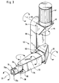
- FIG. 1 An embodiment of a multi-spindle turning machine according to the invention, shown in Fig. 1, comprises a generally designated 10 machine frame having a base 12, on which a stator 14 is arranged, in which a spindle drum 16 is rotatably mounted. On the stand 14, a superstructure 18 is also still arranged.
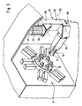
- the spindle drum 16 is, as shown in Fig. 2, rotatable on the stator 14 about a spindle drum axis 20 and has a plurality of preferably at the same radial distance around the spindle drum axis 20 arranged around workpiece spindles S1 to S6, which in turn about spindle axes A1 to A6 are rotatable relative to the spindle drum 16.
- the spindle drum 16 is rotatable relative to the stator 14 about the spindle drum axis 20 such that the individual workpiece spindles S1 to S6 are respectively movable in defined spindle stations ST1 to ST6, the spindle stations ST1 to ST6 being stationary relative to the stator 14 and thus advancing The spindle drum 16, for example, all spindles S1 to S6 can be brought into the spindle station ST1.
- each of the spindle stations ST1 to ST6 is assigned at least one tool carrier 24 which comprises a carriage system with a first carriage 26 which is movable relative to the stator 14 in the direction parallel to the spindle axis A in the respective spindle station ST and thus in a Z direction is and a second carriage 28 which relative to the first carriage 26 in the radial direction to that in the respective spindle station ST stationary spindle axis A and thus in an X direction is movable to move a tool 30 for machining a workpiece 30 in the X direction and the Z direction can.
- tool carrier 24 comprises a carriage system with a first carriage 26 which is movable relative to the stator 14 in the direction parallel to the spindle axis A in the respective spindle station ST and thus in a Z direction is and a second carriage 28 which relative to the first carriage 26 in the radial direction to that in the respective spindle station ST stationary spindle axis A and thus in an X direction is movable to move a tool
- the spindle stations ST are assigned a plurality of such tool carriers 24, for example two such tool carriers 24, as shown in the drawing in the example of the spindle stations ST1, ST2, ST5 and ST6 in FIG.
- each of the workpiece spindles S1 to S6 is provided with a workpiece holder 32 which, depending on the workpiece W, is designed, for example, as a collet or chuck.
- the workpieces W in the workpiece holders 32 are arranged such that they project into a lying in front of an end face 34 of the spindle drum 16 working space 36, wherein - as shown in FIGS. 1 and 2 - both the workpiece holders 32 of Workpiece spindles S1 to S6 as well as the tools 30 of the individual tool carriers 24 are located on the same side of the working space 36 and thus the working space 36 is accessible from its other sides without interference from the tool carrier 24 and the tools 30 and the workpiece holders 32.
- a swivel arm handling device 40 which is arranged in a region 38 located in front of the end face 34 and on a side of the working chamber 36 opposite the end side 34.
- the Schwenkarmhandhabungs worn 40 is provided, which, as shown in Fig. 1 and 3, one of the superstructure 18 in a Over the working space 36 extending away region 41 has arranged arranged foot 42, wherein the foot 42 is fixedly mounted on the region 41 of the superstructure 18.
- a Schwenkarmbasis 46 is rotatably mounted about a predominantlyschwenkachse 44, wherein the subjectschwenkachse 44 extends transversely to a plane 48 which is defined by a base surface 50 of the machine frame 10.
- the predominantlyschwenkachse 44 extends substantially in the vertical direction.
- a designated as a whole with 52 articulated arm is pivotally mounted by means of a first pivot joint 54, wherein the first pivot joint 54 has a transversely, preferably perpendicular to the solicitschwenkachse 44 extending first pivot axis 56.
- the articulated arm 52 comprises a first arm 58 extending from the first pivot joint 54, on which a second arm 64 of the articulated arm 52 is pivotably mounted by means of a articulated joint 60, which is pivotable about a pivot axis 62 parallel to the first pivot axis 56.
- a gripping arm 70 is pivotably mounted on a side opposite the articulated joint 60 by means of a second pivot joint 66, which is pivotable about a second pivot axis 68, which is thus pivotable overall by the second pivot joint 66 relative to the second arm 64 ,
- the second arm 64 is still provided with a transverse to the bending axis 62 axis of rotation 72, which also extends transversely to the second pivot axis 68, so that the second pivot joint 66 relative to the articulated joint 60 is rotatable and thus the second Schwenkarmachse 68 against the bending axis 62 rotatable is, with a vertical orientation of the axis of rotation 72 to the bending axis 62 and the second pivot axis 68, the second pivot axis 68 parallel to the bending axis 62 or perpendicular to the bending axis 62 extending or aligned in all intermediate rotational positions.
- a workpiece gripper 74 is provided on the gripping arm 70, which has, for example, two gripping jaws 76a, 76b in order to grasp the workpieces W.
- the workpiece gripper 74 can be held firmly on the gripper arm 70.
- a suitable solution for non-rotationally symmetrical workpieces provides that the workpiece gripper 74 relative to the Gripping arm 70 is rotatable about a transverse to the second pivot axis 68 extending axis of rotation 78, so as to be able to align the gripping jaws 76a and 76b in different rotational positions relative to the second pivot axis 68 can.
- the foot 42 of the Schwenkarmhandlingungs noticed 40 is arranged relative to the working space 36 that theticianschwenkachse 44, which preferably extends substantially in the vertical direction, is cut by the spindle drum axis 20 so that the foot 42 exactly centered in front of the end face 34 of the spindle drum 16 is, however, so that between the foot 42 and the front side 34 of the spindle drum 16, the working space 36 through which the Schwenkarmhandhabungs responded 40 engages when it wants to access the workpieces W in the workpiece holders 32.
- a maximum distance from a vertical, through the spindle drum axis 20 extending through the middle plane 82 having spindle stations, in Fig. 2 and 6 on the spindle stations ST2 and ST5 is the Schwenkarmhandhabungs worn 40th to rotate about the complicatschwenkachse 44 that the second arm 64 is in access to the workpiece spindle S in the spindle ST5 in a plane parallel to the personallyschwenkachse 44 extending plane 84 and in this by pivoting the articulated arm 52 about the first pivot axis 56 and / or a pivoting of the second arm 64 about the bending axis 62 is movable.
- the plane of movement 84 extends at an angle ⁇ to the vertical center plane 92, which is less than 45 °.
- the swivel arm handling device 40 is movable such that the second arm 64 lies in and can be moved in a plane of movement 86 which also runs parallel to the foot pivot axis 44 and with respect to FIG Center plane 82 is inclined by an angle ⁇ , which is also less than 45 °.
- angles .alpha. And .beta are equal in the case of similar workpieces W; in the case of workpieces W protruding at different distances into the working space 36, the angles .alpha. And .beta. Can be slightly different.
- pivoting of the pivot arm base 46 of the pivot arm handling device 40 about the foot pivot axis 44 is sufficient within an angular range ⁇ that results from the sum of the angles ⁇ and ⁇ when accessing the pivot arm handling device 40 Workpieces W should be possible in all workpiece holders 32 in all spindle stations ST1 to ST6.
- workpiece transport means In order to remove workpieces W from the workpiece holders 32 of the individual spindle stations ST1 to ST6 or to use in this, as a whole designated 90 workpiece transport means is provided which has a workpiece transfer chamber 92 arranged in this workpiece transfer positions 94 which are such that - shown in Fig. 6 - the smallest possible additional pivoting of the Schwenkarmhandhabungs worn 40 is required to the rigorousschwenkachse 44.
- the workpiece transfer positions 94 are indeed arranged on a side of the foot pivot axis 44 opposite the working space 36, but within the angle range between the planes of movement 84 and 86 predetermined by the angle ⁇ , so that it is not necessary to pivot the Schwenkarmhandgriffungs adopted 40 in a larger angular range about the rigorousschwenkachse 44.
- the workpiece transfer chamber 92 On the same side of the contemplatschwenkachse 44 arranged as the working space 36, but is also in this embodiment, the workpiece transfer chamber 92 such that the smallest possible pivoting of the Schwenkarmbasis 46 to the criticallyschwenkachse 44 is required to reach all workpiece transfer positions in the workpiece transfer chamber 92.
- the second embodiment of the multi-spindle turning machine according to the invention has the same parts as the first embodiment, so that the same reference numerals are used for the same parts and otherwise fully incorporated by reference to the comments on the first embodiment.
- the spindle ST5 is associated with a synchronous spindle SS5, which is held on one of the spindle station ST5 associated tool carrier 24 and with this in a coaxial with the spindle axis A5 standing position retractable and off this is out again.
- the workpiece gripper 74 ' is formed as a shaft gripper and has a gripping tongs 96, with which the workpiece gripper 74' is able to grip the workpiece W even if this is held in the synchronous spindle SS5 and thus the workpiece W also take the synchronous spindle SS5 or if necessary also insert into this.
- the tapped and held in the synchronous spindle SS5 workpiece W can then be removed from the workpiece gripper 74 'by means of the Schwenkarmhandhabungs worn 40 in the manner described in connection with the preceding embodiments and spent in the workpiece transfer chamber 92.
- the synchronous spindle SS5 is thus to be considered in the same way for the question of handling, as a further, the spindle ST5 associated workpiece spindle.
- the third embodiment fully corresponds to the preceding embodiments, so that the same parts are provided with the same reference numerals and is fully incorporated by reference to the statements to the preceding embodiments.
Landscapes
- Engineering & Computer Science (AREA)
- Mechanical Engineering (AREA)
- Turning (AREA)
Applications Claiming Priority (2)
| Application Number | Priority Date | Filing Date | Title |
|---|---|---|---|
| DE10310997A DE10310997A1 (de) | 2003-03-06 | 2003-03-06 | Mehrspindeldrehmaschine |
| EP04004319A EP1454711B1 (fr) | 2003-03-06 | 2004-02-26 | Tour multibroche avec manipulateur de pièces articulé |
Related Parent Applications (1)
| Application Number | Title | Priority Date | Filing Date |
|---|---|---|---|
| EP04004319A Division EP1454711B1 (fr) | 2003-03-06 | 2004-02-26 | Tour multibroche avec manipulateur de pièces articulé |
Publications (3)
| Publication Number | Publication Date |
|---|---|
| EP1752255A2 true EP1752255A2 (fr) | 2007-02-14 |
| EP1752255A3 EP1752255A3 (fr) | 2007-02-21 |
| EP1752255B1 EP1752255B1 (fr) | 2009-11-04 |
Family
ID=32797911
Family Applications (2)
| Application Number | Title | Priority Date | Filing Date |
|---|---|---|---|
| EP06021798A Expired - Lifetime EP1752255B1 (fr) | 2003-03-06 | 2004-02-26 | Tour multibroche avec manipulateur de pièces articulé |
| EP04004319A Expired - Lifetime EP1454711B1 (fr) | 2003-03-06 | 2004-02-26 | Tour multibroche avec manipulateur de pièces articulé |
Family Applications After (1)
| Application Number | Title | Priority Date | Filing Date |
|---|---|---|---|
| EP04004319A Expired - Lifetime EP1454711B1 (fr) | 2003-03-06 | 2004-02-26 | Tour multibroche avec manipulateur de pièces articulé |
Country Status (3)
| Country | Link |
|---|---|
| US (1) | US7131359B2 (fr) |
| EP (2) | EP1752255B1 (fr) |
| DE (3) | DE10310997A1 (fr) |
Cited By (1)
| Publication number | Priority date | Publication date | Assignee | Title |
|---|---|---|---|---|
| WO2009081443A3 (fr) * | 2007-12-24 | 2009-10-01 | Buffoli Transfer S.P.A. | Machine de transfert et procédé de travail améliorés |
Families Citing this family (14)
| Publication number | Priority date | Publication date | Assignee | Title |
|---|---|---|---|---|
| JP4833887B2 (ja) * | 2007-02-26 | 2011-12-07 | オークマ株式会社 | タレット刃物台及び工作機械 |
| JP5385675B2 (ja) * | 2009-05-08 | 2014-01-08 | 株式会社森精機製作所 | 旋削加工用工作機械 |
| IT1399706B1 (it) * | 2010-04-09 | 2013-04-26 | Danieli Off Mecc | Macchina per la filettatura di manicotti o simili, e relativo procedimento |
| CN103042430A (zh) * | 2013-01-04 | 2013-04-17 | 江苏天宏自动化科技有限公司 | 一种翻转式横移搬运夹爪 |
| JP6400369B2 (ja) * | 2014-07-24 | 2018-10-03 | Dmg森精機株式会社 | 工作機械及び該工作機械の配置構造 |
| DE102015116582B4 (de) * | 2015-09-30 | 2021-08-05 | Walter Maschinenbau Gmbh | Transportvorrichtung zum Transportieren eines Werkstücks |
| DE102016102952B4 (de) * | 2016-02-19 | 2023-02-02 | Ffg Werke Gmbh | Rundtakt-Werkzeugmaschine |
| CN108817423B (zh) * | 2018-07-26 | 2023-06-09 | 长沙航空职业技术学院 | 一种六轴车床 |
| CN109834299A (zh) * | 2019-01-15 | 2019-06-04 | 陈泽毅 | 双主轴数控车床 |
| IT201900005394A1 (it) * | 2019-04-08 | 2020-10-08 | Proquadro S R L | “Macchina utensile a controllo numerico” |
| IT201900005392A1 (it) * | 2019-04-08 | 2020-10-08 | Proquadro S R L | “Macchina utensile a controllo numerico” |
| CN111230218B (zh) * | 2020-01-27 | 2021-01-19 | 浙江舜特机械设备有限公司 | 一种基于平口的用于换热器生产的加工设备 |
| CN113523314B (zh) * | 2021-07-23 | 2022-06-07 | 四川众友机械有限责任公司 | 三联齿轮加工工艺和加工系统 |
| CN117020727B (zh) * | 2023-07-31 | 2025-12-05 | 厦门财鑫科技有限公司 | 一种数控机床全自动上料机构 |
Family Cites Families (18)
| Publication number | Priority date | Publication date | Assignee | Title |
|---|---|---|---|---|
| US1492103A (en) * | 1921-12-09 | 1924-04-29 | Niles Bementpond Co | Boring mill and the like |
| GB1442598A (en) * | 1972-07-13 | 1976-07-14 | Wickman Mach Tool Sales Ltd | Multi-spindle lathes having automatic workpiece handling apparatus |
| GB1442597A (en) | 1972-07-13 | 1976-07-14 | Wickman Mach Tool Sales Ltd | Multi-spindle lathe having an automatic workpiece loading and unloading apparatus |
| DE8418827U1 (de) * | 1984-06-22 | 1984-09-13 | Gildemeister Ag, 4800 Bielefeld | Werkstueckhandhabungseinrichtung fuer mehrspindel-drehautomaten |
| JPS63180492A (ja) * | 1987-01-21 | 1988-07-25 | 三菱電機株式会社 | 産業用ロボツト装置 |
| EP0298672A3 (fr) * | 1987-07-08 | 1989-12-06 | Wickman Bennett Machine Tool Company Limited | Tour multi-broches |
| US5168886A (en) * | 1988-05-25 | 1992-12-08 | Semitool, Inc. | Single wafer processor |
| JPH0634923Y2 (ja) * | 1988-11-09 | 1994-09-14 | マツダ株式会社 | 研削盤におけるワーク移送装置 |
| US4926723A (en) * | 1988-12-06 | 1990-05-22 | Ralph Earl Co., Inc. | Machine tool auxiliary function hydraulic system |
| DE4023771A1 (de) * | 1990-07-26 | 1992-01-30 | Rainer Dipl Ing Daumann | Werkstueckzu-/abfuehrung fuer cnc-mehrspindeldrehautomat |
| US5153973A (en) * | 1990-11-01 | 1992-10-13 | Kitamura Machinery Co., Ltd. | Work changer |
| US5309368A (en) * | 1992-01-21 | 1994-05-03 | Chern Shyi Tsae | Workpiece handling mechanism of a C-N-C lathe machine |
| US5239901A (en) * | 1992-09-11 | 1993-08-31 | Lin I Nan | CNC lathe |
| US5344264A (en) * | 1993-07-27 | 1994-09-06 | Hevoyan Varoujan H | Vise transport for milling machines |
| US5669751A (en) * | 1994-05-09 | 1997-09-23 | Cincinnati Milacron Inc. | Transport system for workpieces |
| EP0937539A1 (fr) * | 1998-02-24 | 1999-08-25 | Mikron SA Agno | Machine outil avec poste de travail multiple |
| US6640458B2 (en) * | 2002-03-25 | 2003-11-04 | Btm Corporation | End arm effector set-up |
| DE10226272A1 (de) | 2002-06-07 | 2004-01-08 | Index-Werke Gmbh & Co. Kg Hahn & Tessky | Mehrspindelwerkzeugmaschine |
-
2003
- 2003-03-06 DE DE10310997A patent/DE10310997A1/de not_active Ceased
- 2003-08-14 US US10/641,339 patent/US7131359B2/en not_active Expired - Lifetime
-
2004
- 2004-02-26 DE DE502004001975T patent/DE502004001975D1/de not_active Expired - Lifetime
- 2004-02-26 EP EP06021798A patent/EP1752255B1/fr not_active Expired - Lifetime
- 2004-02-26 EP EP04004319A patent/EP1454711B1/fr not_active Expired - Lifetime
- 2004-02-26 DE DE502004010332T patent/DE502004010332D1/de not_active Expired - Lifetime
Cited By (1)
| Publication number | Priority date | Publication date | Assignee | Title |
|---|---|---|---|---|
| WO2009081443A3 (fr) * | 2007-12-24 | 2009-10-01 | Buffoli Transfer S.P.A. | Machine de transfert et procédé de travail améliorés |
Also Published As
| Publication number | Publication date |
|---|---|
| EP1752255B1 (fr) | 2009-11-04 |
| EP1454711B1 (fr) | 2006-11-15 |
| DE502004001975D1 (de) | 2006-12-28 |
| DE10310997A1 (de) | 2004-09-23 |
| US7131359B2 (en) | 2006-11-07 |
| US20040173063A1 (en) | 2004-09-09 |
| EP1454711A1 (fr) | 2004-09-08 |
| EP1752255A3 (fr) | 2007-02-21 |
| DE502004010332D1 (de) | 2009-12-17 |
Similar Documents
| Publication | Publication Date | Title |
|---|---|---|
| DE60037400T2 (de) | Kombinierte drehmaschine mit nc steuerung | |
| EP3147073B1 (fr) | Machine-outil, en particulier fraiseuse multi-broches | |
| EP1733840B1 (fr) | Système de machine-outil avec un robot et un magazin pour outils | |
| EP1193027B1 (fr) | Tour | |
| EP1765550B1 (fr) | Machine-outil | |
| EP1027955B1 (fr) | Machine-outil | |
| EP1454711B1 (fr) | Tour multibroche avec manipulateur de pièces articulé | |
| EP1985411B1 (fr) | Agencement de machines-outils doté d'un changement de pièce et d'outil | |
| DE19749872A1 (de) | Drehmaschine | |
| EP1118428B2 (fr) | Tour | |
| EP1976665A1 (fr) | Machine-outil | |
| EP1570946B1 (fr) | Machine-outil avec au moins deux broches porte-outils et un disque à outils | |
| EP0995539A2 (fr) | Dispositif d'usinage de pièces | |
| EP0885686A1 (fr) | Centre d'usinage | |
| EP0154349B1 (fr) | Dispositif pour changer des outils ou des objets similaires dans la broche d'une machine-outil | |
| DE102013003769B4 (de) | Verzahnmaschine und Verfahren zur Herstellung eines verzahnten Werkstückes | |
| EP2881219B1 (fr) | Dispositif de changement d'outil destiné à être utilisé dans un centre d'usinage et centre d'usinage destiné à l'usinage mécanique d'une pièce à usiner | |
| EP1511596B1 (fr) | Tour multibroche | |
| EP1179387B1 (fr) | Machine outil pourvu d'une pince d'outillage et/ou d'un système de magasin d'outil | |
| DE102006042006B4 (de) | Drehmaschine | |
| EP1752241B1 (fr) | Tour d'usinage | |
| EP0129677A2 (fr) | Centre d'usinage pour travaux de fraisage et de perçage | |
| EP4201585A1 (fr) | Machine-outil multibroche | |
| DE102004004019B4 (de) | Drehmaschine | |
| DE20321615U1 (de) | Mehrspindeldrehmaschine |
Legal Events
| Date | Code | Title | Description |
|---|---|---|---|
| PUAI | Public reference made under article 153(3) epc to a published international application that has entered the european phase |
Free format text: ORIGINAL CODE: 0009012 |
|
| PUAL | Search report despatched |
Free format text: ORIGINAL CODE: 0009013 |
|
| AC | Divisional application: reference to earlier application |
Ref document number: 1454711 Country of ref document: EP Kind code of ref document: P |
|
| AK | Designated contracting states |
Kind code of ref document: A2 Designated state(s): CH CZ DE FR IT LI |
|
| AK | Designated contracting states |
Kind code of ref document: A3 Designated state(s): CH CZ DE FR IT LI |
|
| 17P | Request for examination filed |
Effective date: 20070817 |
|
| 17Q | First examination report despatched |
Effective date: 20070924 |
|
| AKX | Designation fees paid |
Designated state(s): CH CZ DE FR IT LI |
|
| GRAP | Despatch of communication of intention to grant a patent |
Free format text: ORIGINAL CODE: EPIDOSNIGR1 |
|
| GRAS | Grant fee paid |
Free format text: ORIGINAL CODE: EPIDOSNIGR3 |
|
| GRAA | (expected) grant |
Free format text: ORIGINAL CODE: 0009210 |
|
| AC | Divisional application: reference to earlier application |
Ref document number: 1454711 Country of ref document: EP Kind code of ref document: P |
|
| AK | Designated contracting states |
Kind code of ref document: B1 Designated state(s): CH CZ DE FR IT LI |
|
| REG | Reference to a national code |
Ref country code: CH Ref legal event code: EP |
|
| REF | Corresponds to: |
Ref document number: 502004010332 Country of ref document: DE Date of ref document: 20091217 Kind code of ref document: P |
|
| REG | Reference to a national code |
Ref country code: DE Ref legal event code: R096 Ref document number: 502004010332 Country of ref document: DE Effective date: 20091217 |
|
| REG | Reference to a national code |
Ref country code: CH Ref legal event code: NV Representative=s name: KIRKER & CIE S.A. |
|
| PG25 | Lapsed in a contracting state [announced via postgrant information from national office to epo] |
Ref country code: CZ Free format text: LAPSE BECAUSE OF FAILURE TO SUBMIT A TRANSLATION OF THE DESCRIPTION OR TO PAY THE FEE WITHIN THE PRESCRIBED TIME-LIMIT Effective date: 20091104 |
|
| PLBE | No opposition filed within time limit |
Free format text: ORIGINAL CODE: 0009261 |
|
| STAA | Information on the status of an ep patent application or granted ep patent |
Free format text: STATUS: NO OPPOSITION FILED WITHIN TIME LIMIT |
|
| 26N | No opposition filed |
Effective date: 20100805 |
|
| REG | Reference to a national code |
Ref country code: DE Ref legal event code: R097 Ref document number: 502004010332 Country of ref document: DE Effective date: 20100805 |
|
| REG | Reference to a national code |
Ref country code: DE Ref legal event code: R082 Ref document number: 502004010332 Country of ref document: DE Representative=s name: HOEGER, STELLRECHT & PARTNER PATENTANWAELTE MB, DE |
|
| REG | Reference to a national code |
Ref country code: FR Ref legal event code: PLFP Year of fee payment: 13 |
|
| REG | Reference to a national code |
Ref country code: FR Ref legal event code: PLFP Year of fee payment: 14 |
|
| REG | Reference to a national code |
Ref country code: FR Ref legal event code: PLFP Year of fee payment: 15 |
|
| REG | Reference to a national code |
Ref country code: DE Ref legal event code: R082 Ref document number: 502004010332 Country of ref document: DE Representative=s name: HOEGER, STELLRECHT & PARTNER PATENTANWAELTE MB, DE |
|
| PGFP | Annual fee paid to national office [announced via postgrant information from national office to epo] |
Ref country code: FR Payment date: 20230221 Year of fee payment: 20 Ref country code: CH Payment date: 20230303 Year of fee payment: 20 |
|
| PGFP | Annual fee paid to national office [announced via postgrant information from national office to epo] |
Ref country code: IT Payment date: 20230216 Year of fee payment: 20 Ref country code: DE Payment date: 20230227 Year of fee payment: 20 |
|
| P01 | Opt-out of the competence of the unified patent court (upc) registered |
Effective date: 20230517 |
|
| REG | Reference to a national code |
Ref country code: DE Ref legal event code: R071 Ref document number: 502004010332 Country of ref document: DE |
|
| REG | Reference to a national code |
Ref country code: CH Ref legal event code: PL |