EP1752409A2 - Dispositif d'assemblage avec quatre rails et procédé d'assemblage - Google Patents
Dispositif d'assemblage avec quatre rails et procédé d'assemblage Download PDFInfo
- Publication number
- EP1752409A2 EP1752409A2 EP06254185A EP06254185A EP1752409A2 EP 1752409 A2 EP1752409 A2 EP 1752409A2 EP 06254185 A EP06254185 A EP 06254185A EP 06254185 A EP06254185 A EP 06254185A EP 1752409 A2 EP1752409 A2 EP 1752409A2
- Authority
- EP
- European Patent Office
- Prior art keywords
- workload
- carriage
- quadrail
- disposed
- moving
- Prior art date
- Legal status (The legal status is an assumption and is not a legal conclusion. Google has not performed a legal analysis and makes no representation as to the accuracy of the status listed.)
- Granted
Links
Images


Classifications
-
- F—MECHANICAL ENGINEERING; LIGHTING; HEATING; WEAPONS; BLASTING
- F01—MACHINES OR ENGINES IN GENERAL; ENGINE PLANTS IN GENERAL; STEAM ENGINES
- F01D—NON-POSITIVE DISPLACEMENT MACHINES OR ENGINES, e.g. STEAM TURBINES
- F01D25/00—Component parts, details, or accessories, not provided for in, or of interest apart from, other groups
- F01D25/28—Supporting or mounting arrangements, e.g. for turbine casing
-
- B—PERFORMING OPERATIONS; TRANSPORTING
- B66—HOISTING; LIFTING; HAULING
- B66C—CRANES; LOAD-ENGAGING ELEMENTS OR DEVICES FOR CRANES, CAPSTANS, WINCHES, OR TACKLES
- B66C11/00—Trolleys or crabs, e.g. operating above runways
- B66C11/02—Trolleys or crabs, e.g. operating above runways with operating gear or operator's cabin suspended, or laterally offset, from runway or track
- B66C11/04—Underhung trolleys
-
- B—PERFORMING OPERATIONS; TRANSPORTING
- B66—HOISTING; LIFTING; HAULING
- B66C—CRANES; LOAD-ENGAGING ELEMENTS OR DEVICES FOR CRANES, CAPSTANS, WINCHES, OR TACKLES
- B66C11/00—Trolleys or crabs, e.g. operating above runways
- B66C11/12—Trolleys or crabs, e.g. operating above runways having hoisting gear adapted to special load-engaging elements and not otherwise provided for
-
- F—MECHANICAL ENGINEERING; LIGHTING; HEATING; WEAPONS; BLASTING
- F01—MACHINES OR ENGINES IN GENERAL; ENGINE PLANTS IN GENERAL; STEAM ENGINES
- F01D—NON-POSITIVE DISPLACEMENT MACHINES OR ENGINES, e.g. STEAM TURBINES
- F01D25/00—Component parts, details, or accessories, not provided for in, or of interest apart from, other groups
- F01D25/28—Supporting or mounting arrangements, e.g. for turbine casing
- F01D25/285—Temporary support structures, e.g. for testing, assembling, installing, repairing; Assembly methods using such structures
-
- F—MECHANICAL ENGINEERING; LIGHTING; HEATING; WEAPONS; BLASTING
- F05—INDEXING SCHEMES RELATING TO ENGINES OR PUMPS IN VARIOUS SUBCLASSES OF CLASSES F01-F04
- F05D—INDEXING SCHEME FOR ASPECTS RELATING TO NON-POSITIVE-DISPLACEMENT MACHINES OR ENGINES, GAS-TURBINES OR JET-PROPULSION PLANTS
- F05D2230/00—Manufacture
- F05D2230/60—Assembly methods
- F05D2230/68—Assembly methods using auxiliary equipment for lifting or holding
-
- Y—GENERAL TAGGING OF NEW TECHNOLOGICAL DEVELOPMENTS; GENERAL TAGGING OF CROSS-SECTIONAL TECHNOLOGIES SPANNING OVER SEVERAL SECTIONS OF THE IPC; TECHNICAL SUBJECTS COVERED BY FORMER USPC CROSS-REFERENCE ART COLLECTIONS [XRACs] AND DIGESTS
- Y02—TECHNOLOGIES OR APPLICATIONS FOR MITIGATION OR ADAPTATION AGAINST CLIMATE CHANGE
- Y02T—CLIMATE CHANGE MITIGATION TECHNOLOGIES RELATED TO TRANSPORTATION
- Y02T50/00—Aeronautics or air transport
- Y02T50/60—Efficient propulsion technologies, e.g. for aircraft
-
- Y—GENERAL TAGGING OF NEW TECHNOLOGICAL DEVELOPMENTS; GENERAL TAGGING OF CROSS-SECTIONAL TECHNOLOGIES SPANNING OVER SEVERAL SECTIONS OF THE IPC; TECHNICAL SUBJECTS COVERED BY FORMER USPC CROSS-REFERENCE ART COLLECTIONS [XRACs] AND DIGESTS
- Y10—TECHNICAL SUBJECTS COVERED BY FORMER USPC
- Y10T—TECHNICAL SUBJECTS COVERED BY FORMER US CLASSIFICATION
- Y10T29/00—Metal working
- Y10T29/49—Method of mechanical manufacture
- Y10T29/49316—Impeller making
- Y10T29/4932—Turbomachine making
-
- Y—GENERAL TAGGING OF NEW TECHNOLOGICAL DEVELOPMENTS; GENERAL TAGGING OF CROSS-SECTIONAL TECHNOLOGIES SPANNING OVER SEVERAL SECTIONS OF THE IPC; TECHNICAL SUBJECTS COVERED BY FORMER USPC CROSS-REFERENCE ART COLLECTIONS [XRACs] AND DIGESTS
- Y10—TECHNICAL SUBJECTS COVERED BY FORMER USPC
- Y10T—TECHNICAL SUBJECTS COVERED BY FORMER US CLASSIFICATION
- Y10T29/00—Metal working
- Y10T29/49—Method of mechanical manufacture
- Y10T29/49826—Assembling or joining
- Y10T29/49828—Progressively advancing of work assembly station or assembled portion of work
-
- Y—GENERAL TAGGING OF NEW TECHNOLOGICAL DEVELOPMENTS; GENERAL TAGGING OF CROSS-SECTIONAL TECHNOLOGIES SPANNING OVER SEVERAL SECTIONS OF THE IPC; TECHNICAL SUBJECTS COVERED BY FORMER USPC CROSS-REFERENCE ART COLLECTIONS [XRACs] AND DIGESTS
- Y10—TECHNICAL SUBJECTS COVERED BY FORMER USPC
- Y10T—TECHNICAL SUBJECTS COVERED BY FORMER US CLASSIFICATION
- Y10T29/00—Metal working
- Y10T29/49—Method of mechanical manufacture
- Y10T29/49826—Assembling or joining
- Y10T29/49895—Associating parts by use of aligning means [e.g., use of a drift pin or a "fixture"]
-
- Y—GENERAL TAGGING OF NEW TECHNOLOGICAL DEVELOPMENTS; GENERAL TAGGING OF CROSS-SECTIONAL TECHNOLOGIES SPANNING OVER SEVERAL SECTIONS OF THE IPC; TECHNICAL SUBJECTS COVERED BY FORMER USPC CROSS-REFERENCE ART COLLECTIONS [XRACs] AND DIGESTS
- Y10—TECHNICAL SUBJECTS COVERED BY FORMER USPC
- Y10T—TECHNICAL SUBJECTS COVERED BY FORMER US CLASSIFICATION
- Y10T29/00—Metal working
- Y10T29/49—Method of mechanical manufacture
- Y10T29/49998—Work holding
-
- Y—GENERAL TAGGING OF NEW TECHNOLOGICAL DEVELOPMENTS; GENERAL TAGGING OF CROSS-SECTIONAL TECHNOLOGIES SPANNING OVER SEVERAL SECTIONS OF THE IPC; TECHNICAL SUBJECTS COVERED BY FORMER USPC CROSS-REFERENCE ART COLLECTIONS [XRACs] AND DIGESTS
- Y10—TECHNICAL SUBJECTS COVERED BY FORMER USPC
- Y10T—TECHNICAL SUBJECTS COVERED BY FORMER US CLASSIFICATION
- Y10T29/00—Metal working
- Y10T29/53—Means to assemble or disassemble
- Y10T29/53435—Means to assemble or disassemble including assembly pallet
-
- Y—GENERAL TAGGING OF NEW TECHNOLOGICAL DEVELOPMENTS; GENERAL TAGGING OF CROSS-SECTIONAL TECHNOLOGIES SPANNING OVER SEVERAL SECTIONS OF THE IPC; TECHNICAL SUBJECTS COVERED BY FORMER USPC CROSS-REFERENCE ART COLLECTIONS [XRACs] AND DIGESTS
- Y10—TECHNICAL SUBJECTS COVERED BY FORMER USPC
- Y10T—TECHNICAL SUBJECTS COVERED BY FORMER US CLASSIFICATION
- Y10T29/00—Metal working
- Y10T29/53—Means to assemble or disassemble
- Y10T29/53539—Means to assemble or disassemble including work conveyor
- Y10T29/53543—Means to assemble or disassemble including work conveyor including transporting track
- Y10T29/53548—Means to assemble or disassemble including work conveyor including transporting track and work carrying vehicle
Definitions
- This invention relates to an ergonomic assembly process and, more particularly, relates to a quadrail ergonomic assembly process.
- the single point overhead hoist method has been employed throughout many industries. For instance, gas turbine engine manufacturers employ this method and others such as elevated rails and supports, static posts, and the like, which all employ hoists, to suspend engines and complete their assembly. For instance, elevated rails and supports may ultimately support the engine but a hoist must be employed to effectively place the engine upon the rails. And, static posts require the same hoisting procedure when placing the engine upon the typically used jack stands.
- a worker's safety may be compromised due to the potential for a suspended, dangling workload to fall.
- the engine itself must be assembled precisely and properly.
- An engine suspended from a hoist may potentially fall, inadvertently knock into another object or static structure, or suffer physical damage as a part to be installed inadvertently slips and falls within the engine.
- the "foreign object" must then be removed from within the engine and properly installed. However, each time the foreign object contacts an internal part, while falling through the engine, additional repairs may be required.
- a quadrail ergonomic apparatus broadly comprises two or more pathways designed to permit movement in two or more directions mounted to a static object above a surface; one or more carriages designed to move in two or more directions disposed within the two or more pathways; wherein each carriage is suspended above the surface from the pathways and is capable of maintaining a workload in place and permitting movement of the workload in at least four directions.
- a method for ergonomically assembling an apparatus comprises providing five or more carriages disposed in connection with two or more pathways mounted to a static object above a surface; disposing a workload in one or more of the five or more carriages; positioning each carriage containing the workload in a spatial relationship to one another; and assembling each of the workloads together using each of the carriages to form an apparatus.
- a quadrail ergonomic apparatus for use in assembling a product typically requiring the use of a hoist is described herein.
- the apparatus and its method of use employs a multiple rail system for suspending several carriages designed to hold parts of a product to be assembled.
- the carriages possess multiple degrees of freedom of motion in order to maintain, manipulate and orient the part making up the product.
- One or more workers may then complete assembly of each part, and then assemble the parts suspended within the carriages.
- the product may be assembled while disposed in a horizontal position.
- the work zone surrounding the suspended parts is ergonomically optimized by the vertically, axially and rotationally orienting the parts alone, and in combination, throughout the process.
- Asymmetric turbomachinery may also be assembled with ease due to the rotational capabilities of the carriages described herein as well as the ability to stack parts with core machinery, to variably adjust the height of the parts and core machinery and to flexibly manipulate the centerline of the parts and core machinery.
- the method for use of the quadrail ergonomic apparatus described herein is not limited to part and/or module level assembly processes, but may also be applicable to production, overhaul and the like.
- Each carriage may be capable of generally receiving and maintaining a workload or, more particularly, a part of a product to be assembled.
- the word "maintaining” is generally understood to mean the ability to secure a part in place, the ability to hold the part in place, and the ability to support or carry the weight of the part for any period of time.
- Each carriage may operate independently of each other, may be positioned and moved with precision, e.g., within a few thousandths of an inch, in any one of the directions described herein, and each may move at variable speeds alone or in combination with one another within and along the rails.
- Each carriage may maintain weights up to about 10,000 lbs (4550 kg).
- the carriages may be outfitted with logic systems and control modules to enable their self-alignment alone and in combination with each other and movement within and along the rails.
- logic systems and control modules are commercially available from Allen-Bradley, part of Rockwell Automation whose headquarters are located in Milwaukee, Wisconsin.
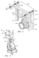
- a quadrail ergonomic apparatus 10 generally comprises a first pathway 11 comprising rails 12, 14, and a second pathway 13 comprising rails 16, 18 mounted to a static structure (not shown), that is, a stationary structure such as a ceiling or truss; each rail 12, 14, 16, 18 may be capable of receiving one or more carriages 20, 22, 24, 26, 28 and suspending carriages 20, 22, 24, 26, 28 above a surface (not shown). Each rail 12, 14, 16, 18 may comprise one or more mating features (not shown) capable of receiving a complementary mating feature disposed upon each carriage 20, 22, 24, 26, 28.
- First pathway 11 may operate independently of second pathway 13, and vice-versa.
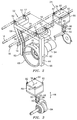
- first carriage 20 may comprise a body 30, one or more mating features 32 complementary to the mating feature of rails 16, 18 mounted to body 30 and means for suspending a part 34 above the surface and moving part 34 in four or more directions.
- Complementary mating features 32 may be disposed within rails 16, 18 to permit the movement of first carriage 20 in the direction(s) and range of motion allowed by rails 16, 18.
- the directions and range of motion allowed by rails 16, 18 permit first carriage 20 to move horizontally. However, this movement may be characterized differently depending upon the location of a worker with respect to first carriage 20.
- a worker standing on either side of part 34 [disposed within first carriage 20] has the perspective such that first carriage may be moved horizontally within rails 16, 18 in a left-to-right direction and a right-to-left direction as indicated by an arrow 36.
- a worker standing in front of part 34 [disposed within first carriage 20] has the perspective such that first carriage 20 may be moved horizontally within rails 16, 18 in a forward-to-backward direction and a backward-to-forward direction as also indicated by arrow 36.
- the means for suspending and moving part 34 may comprise an adjustable arm 38 comprising a first end 40 disposed in connection with body 30 and a second end 42 disposed in connection with part 34.
- Adjustable arm 38 may be capable of permitting part 34 to move vertically upwards and downwards in relation to the surface below as indicated by an arrow 44.
- adjustable arm 38 may be disposed in connection with body 30 such that a pivot mount, swivel mount, rotatable mount, ball-joint socket mount or any mount permitting the three hundred sixty degree rotation of adjustable arm 38 within body 30 in a clockwise direction and a counter-clockwise direction as indicated by an arrow 46.
- second carriage 22 may comprise a body 50, one or more mating features 52 complementary to a mating feature of rails 12, 14 mounted to body 50, and means for suspending a part 54 above the surface and moving part 54 in six or more directions.
- complementary mating features 52 may be disposed within rails 12, 14 to permit the movement of second carriage 22 in the direction(s) and range of motion allowed by rails 12, 14.
- the direction(s) and ranges of motion permitted by rails 12, 14 include those already described with respect to arrow 36.
- the means for suspending and moving said part 54 may comprise a first adjustable arm 56 comprising a first end 58 disposed in connection with body 50 and a second end 60 disposed in connection with part 54, a second adjustable arm 62 comprising a first end 64 disposed in connection with body 50 and a second end 66 disposed in connection with part 54, and a substantially circular harness capable 68 of accepting part 54.
- Body 50 may comprise a U-shaped cross-bar 74 to which both first adjustable arm 56 and second adjustable arm 62 are connected.
- Substantially circular harness 68 may concentrically maintain part 54 and permit its movement in a clockwise direction and a counter-clockwise direction as indicated by an arrow 70 about an axis 72.
- substantially circular harness 68 may also be known as a rollover ring.
- part 54 When part 54 is disposed within substantially circular harness 68, part 54 may be revolved about axis 72 so that the underside of part 54 may be exposed, and a worker may access the undercarriage of part 54 without the need to otherwise crawl underneath part 54.
- Substantially circular harness 68 may further comprise a lower half 68A and an upper half 68B such that lower half 68A may disengage from part 54 while carriage 22 still safely maintains part 54 in position.
- Carriage 22 may further comprise an electronic device designed to track its movement in relation to the other carriages and ensure their alignment in all directions with respect to each other.
- third carriage 24 may comprise a body 80, one or more mating features 82 complementary to the mating feature of rails 16, 18 mounted to body 80 and means for suspending a part 84 above the surface and moving part 84 in four or more directions.
- Complementary mating features 82 may be disposed within rails 16, 18 to permit the movement of third carriage 80 in the direction(s) and range of motion allowed by rails 16, 18.
- the directions and range of motion allowed by rails 16, 18 permit third carriage 80 to move horizontally as indicated by arrow 36. As described earlier, this movement may be characterized differently depending upon the location of a worker with respect to third carriage 80.
- the means for suspending and moving part 84 may comprise an adjustable arm 88 comprising a first end 90 disposed in connection with body 80 and a second end 92 disposed in connection with part 84.
- Adjustable arm 88 may be capable of permitting part 84 to move vertically upwards and downwards in relation to the surface below as indicated by an arrow 44.
- adjustable arm 88 may be disposed in connection with body 80 such that a pivot mount, swivel mount, rotatable mount, ball-joint socket mount or any mount permitting the three hundred sixty degree rotation of adjustable arm 88 within body 80 in a clockwise direction and a counter-clockwise direction as indicated by an arrow 46.
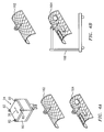
- fourth carriage 26 may comprise a body 100, one or more mating features 102 complementary to a mating feature of rails 12, 14 mounted to body 100, and means for suspending a part 104 above the surface and moving part 104 in six or more directions.
- Complementary mating features 102 may be disposed within rails 12, 14 to permit the movement of fourth carriage 26 in the direction(s) and range of motion allowed by rails 12, 14.
- the direction(s) and ranges of motion permitted by rails 12, 14 include those already described with respect to arrow 36.
- the means for suspending and moving said part 104 may comprise a first adjustable arm 106 comprising a first end 108 disposed in connection with body 100 and a second end 110 disposed in connection with a substantially circular harness support 120, a second adjustable arm 112 comprising a first end 114 disposed in connection with body 100 and a second end 116 disposed in connection with substantially circular harness support 120, and a substantially circular harness capable 118 of accepting part 104.
- first adjustable arm 106 and second adjustable arm 112 are capable of moving vertically upwards and downwards in relation to the surface and capable of moving horizontally in relation to the directions permitted by rails 12, 14 as indicated by arrow 36.
- substantially circular harness support 120 comprises a cross-bar comprising a first end disposed in connection with said second end 110 of first adjustable arm 106, a second end disposed in connection with second end 116 of second adjustable arm 112, and a mount for substantially circular harness 118 disposed therebetween.
- the substantially circular harness may concentrically maintain the part and permit its movement in a clockwise direction and a counter-clockwise direction as indicated by an arrow 122 about an axis 72.
- substantially circular harness 118 may also be known as a rollover ring.
- substantially circular harness may further comprise a lower half 118A and an upper half 118B which permits the removal of lower half 118A while still maintaining safely the part within carriage 26.
- fifth carriage 28 may comprise a body 130, one or more mating features 132 complementary to a mating feature of rails 16, 18 mounted to body 130, and means for suspending a part 134 above the surface and moving part 134 in six or more directions.
- Complementary mating features 132 may be disposed within rails 16, 18 to permit the movement of fifth carriage 28 in the direction(s) and range of motion allowed by rails 16, 18.
- the direction(s) and ranges of motion permitted by rails 16, 18 include those already described with respect to arrow 36.
- the means for suspending and moving part 134 comprises a first adjustable arm 136 comprising a first end 138 disposed in connection with said body 130 and a second end 140 disposed in connection with part 134 and comprising means for rotating a part about axis 142 parallel to the surface disposed in connection with part 134, and a second adjustable arm 146 comprising a first end 148 disposed in connection with body 130 and a second end 150 comprising means for rotating a part about axis 142 parallel to the surface disposed in connection with part 134.
- the means for rotating a part may be capable of rotating part 134 about axis 142 in a clockwise direction and a counter-clockwise direction as indicated by an arrow 152.
- first adjustable arm 136 and second adjustable arm 146 are capable of moving vertically upwards and downwards in relation to the surface and capable of moving horizontally in relation to the directions permitted by rails 16, 18 as indicated by arrow 36.
- quadrail ergonomic apparatus 10 will be described with respect to its use in assembling a gas turbine engine for an aircraft.
- assembly of a gas turbine engine may encompass one or more of the following steps in any particular order, the steps outlined are merely representative and do not constitute the only sequence and/or method(s) for assembling a gas turbine engine using the quadrail ergonomic apparatus described herein.
- the vertical height(s) and horizontal and rotational positioning of each part may be continuously adjusted to maintain an ergonomic work zone.
- quadrail ergonomic apparatus 10 may be mounted to a static structure (not shown) such that rails 12, 14, 16, 18 are mounted above a surface (not shown) and carriages 20, 22, 24, 26, 28 are suspended from the aforementioned rails via their respective mating parts and complimentary mating parts.
- a core, or part 84 may be positioned to be received by carriage 24.
- the core may at least comprise a turbine, a compressor and a combustor, already assembled.
- the core may be positioned beneath carriage 24 using any number of transportation devices such as, but not limited to, a CAPTAM stand, a loading cart, a side loading cart, and the like.
- a captan stand 160 may be utilized to position the core.
- carriage 24 may load the core onto carriage 22 such that the core may be concentrically received by substantially circular harness 68.
- Carriage 24 may be positioned to engage carriage 22 using rails 16, 18 while moving in the direction indicated by arrow 36.
- the core Once received by carriage 22, the core may be moved horizontally (arrow 36), vertically (arrow 44) and rotated about axis 72 (arrow 70) to permit workers complete access to the surface of the core.
- Carriage 22 may then determine whether the carriages are aligned vertically and horizontally with respect to one other and emits a signal to indicate that proper alignment is achieved. Once alignment is confirmed, carriage 24 may then receive other parts such as a low pressure turbine module (part 84), an upper fan duct (a part 162) and a lower fan duct (a part 164), not necessarily in that order, for assembly with the core (see FIG. 4B). As described earlier, these parts may be positioned to be received by carriage 24 using any one of, or a combination of, the aforementioned transportation devices, and the like, such as a side loading cart 168. Afterwards, carriage 24 may receive an augmentor duct (part 104) positioned using an aforementioned transportation device.
- a low pressure turbine module part 84
- an upper fan duct a part 162
- a lower fan duct a part 164
- Carriage 24 may engage carriage 26 and load the augmentor duct therein such that the augmentor duct may be concentrically disposed within substantially circular harness 118. Carriage 26 may then maintain the augmentor duct and permit workers to position the duct vertically and horizontally as well as rotate the duct in the directions indicated by arrow 122 along axis 72. (see FIG. 5)
- a fan module e.g., part 34
- Carriage 20 may engage carriage 22 at least in one of the directions indicated by arrow 36 in order to assemble together the fan module and core (part 54) maintained by carriage 22.
- a nozzle e.g., part 134
- Carriage 28 may engage 26 at least in one of the directions indicated by arrow 36 in order to assemble together the nozzle with the augmentor duct (part 104) maintained by carriage 26.
- External plumbing, controls and an accessory gearbox 166, and other parts not mentioned but within the scope of the aforementioned assembly process, may be ergonomically installed at the "ideal" angular and vertical location(s) relative to the workers perspective as is recognized and appreciated by one of ordinary skill in the art.
- the weight of the gas turbine engine may be principally supported by carriages 24, 26, which permits the removal of carriage 22 at some point as determined by one of ordinary skill in the art.
- a lower half of substantially circular harness 118A may be removed from carriage 26 such that lower half 118A may disengage from the gas turbine engine.
- the gas turbine engine is still maintained safely by carriages 24, 26.
- the gas turbine engine may then be lowered downwards as indicated by arrow 44 towards the surface and onto one of the aforementioned transportation devices.
Landscapes
- Engineering & Computer Science (AREA)
- Mechanical Engineering (AREA)
- General Engineering & Computer Science (AREA)
- Automatic Assembly (AREA)
- Invalid Beds And Related Equipment (AREA)
- Warehouses Or Storage Devices (AREA)
- Carriers, Traveling Bodies, And Overhead Traveling Cranes (AREA)
- Accommodation For Nursing Or Treatment Tables (AREA)
- Handcart (AREA)
Applications Claiming Priority (1)
| Application Number | Priority Date | Filing Date | Title |
|---|---|---|---|
| US11/203,026 US7779540B2 (en) | 2005-08-12 | 2005-08-12 | Apparatus and method for quadrail ergonomic assembly |
Publications (3)
| Publication Number | Publication Date |
|---|---|
| EP1752409A2 true EP1752409A2 (fr) | 2007-02-14 |
| EP1752409A3 EP1752409A3 (fr) | 2010-02-17 |
| EP1752409B1 EP1752409B1 (fr) | 2013-01-02 |
Family
ID=37428708
Family Applications (1)
| Application Number | Title | Priority Date | Filing Date |
|---|---|---|---|
| EP06254185A Not-in-force EP1752409B1 (fr) | 2005-08-12 | 2006-08-09 | Dispositif d'assemblage avec quatre rails et procédé d'assemblage |
Country Status (9)
| Country | Link |
|---|---|
| US (1) | US7779540B2 (fr) |
| EP (1) | EP1752409B1 (fr) |
| JP (1) | JP2007051008A (fr) |
| CN (1) | CN1915784A (fr) |
| AU (1) | AU2006201872A1 (fr) |
| BR (1) | BRPI0601610A (fr) |
| NO (1) | NO20063506L (fr) |
| NZ (1) | NZ547207A (fr) |
| SG (1) | SG130123A1 (fr) |
Cited By (12)
| Publication number | Priority date | Publication date | Assignee | Title |
|---|---|---|---|---|
| EP2811123A1 (fr) * | 2013-06-04 | 2014-12-10 | General Electric Company | Appareil pour pivoter une portion supérieure d'un carter de turbine |
| EP2955339A1 (fr) * | 2014-06-13 | 2015-12-16 | Gabrielle Murphy | Procede et systeme d'assemblage de moteur a turbine a gaz |
| WO2016198216A1 (fr) * | 2015-05-07 | 2016-12-15 | Nuovo Pignone Tecnologie Srl | Appareil d'assemblage/désassemblage pour dispositif mécanique à bride et procédé d'assemblage/désassemblage pour dispositifs mécaniques à bride |
| WO2017023181A1 (fr) * | 2015-08-06 | 2017-02-09 | General Electric Company | Ensemble d'alignement de structure de système de turbine |
| WO2017020881A1 (fr) * | 2015-07-31 | 2017-02-09 | MTU Aero Engines AG | Chariot de guidage pour un élément constitutif de réacteur |
| WO2017116242A1 (fr) * | 2015-12-31 | 2017-07-06 | General Electric Company | Bras de levage d'ensemble chambre de combustion, systèmes de levage d'ensemble chambre de combustion et turbomachines comportant ceux-ci |
| FR3068078A1 (fr) * | 2017-06-27 | 2018-12-28 | Safran Aircraft Engines | Dispositif et procede pour l'assemblage d'une turbomachine |
| WO2019068985A1 (fr) * | 2017-10-06 | 2019-04-11 | Safran Aircraft Engines | Dispositif pour l'assemblage d'une turbomachine, et procede utilisant le dispositif |
| EP3690203A1 (fr) * | 2019-02-01 | 2020-08-05 | Rolls-Royce plc | Système et procédé permettant d'assembler des composants d'un moteur à turbine à gaz |
| IT202200001070A1 (it) * | 2022-01-24 | 2023-07-24 | Nuovo Pignone Tecnologie Srl | Sistema per assemblare una turbomacchina |
| WO2024126921A1 (fr) * | 2022-12-16 | 2024-06-20 | Safran Nacelles | Outillage de manutention d'un capot d'entrée de turbomachine d'aéronef |
| RU2839890C2 (ru) * | 2022-01-24 | 2025-05-13 | НУОВО ПИНЬОНЕ ТЕКНОЛОДЖИ - С.р.л. | Система сборки турбомашины |
Families Citing this family (32)
| Publication number | Priority date | Publication date | Assignee | Title |
|---|---|---|---|---|
| DE102005052077B4 (de) * | 2005-10-28 | 2016-11-24 | Man Diesel & Turbo Se | Vorrichtung zur seitlichen Montage und Demontage eines Kompressorbarrels |
| US8672606B2 (en) * | 2006-06-30 | 2014-03-18 | Solar Turbines Inc. | Gas turbine engine and system for servicing a gas turbine engine |
| US7976266B2 (en) * | 2006-06-30 | 2011-07-12 | Solar Turbines Inc | Power system |
| US20080187431A1 (en) * | 2006-06-30 | 2008-08-07 | Ian Trevor Brown | Power system |
| US8590151B2 (en) * | 2006-06-30 | 2013-11-26 | Solar Turbines Inc. | System for supporting and servicing a gas turbine engine |
| US8061018B2 (en) * | 2007-11-30 | 2011-11-22 | Medallion Instrumentation Systems Llc | Machine for assembling fluid level senders |
| US7963542B2 (en) * | 2008-08-29 | 2011-06-21 | Solar Turbines Incorporated | Modular cart for a gas turbine engine |
| US9032620B2 (en) * | 2008-12-12 | 2015-05-19 | Nuovo Pignone S.P.A. | Method for moving and aligning heavy device |
| FR2952921B1 (fr) * | 2009-11-20 | 2012-05-25 | Snecma | Chariot de transport d'un module de moteur d'aeronef |
| CN102059549B (zh) * | 2010-11-12 | 2012-11-21 | 浙江大学 | 基于四个数控定位器的飞机发动机调姿安装系统及使用方法 |
| US8683670B2 (en) * | 2010-12-20 | 2014-04-01 | Turbine Tooling Solutions Llc | Method for partial disassembly of a bypass turbofan engine |
| US9228451B2 (en) * | 2011-05-03 | 2016-01-05 | Pratt & Whitney Canada Corp. | Gas turbine engine module adapter to a carrier |
| US20130233997A1 (en) * | 2012-03-12 | 2013-09-12 | United Technologies Corporation | Turbine engine case mount |
| US9476323B2 (en) * | 2012-05-31 | 2016-10-25 | United Technologies Corporation | Turbine gear assembly support having symmetrical removal features |
| US8910374B2 (en) * | 2012-10-04 | 2014-12-16 | General Electric Company | Service apparatus for turbomachine |
| US8931170B2 (en) * | 2012-12-12 | 2015-01-13 | Solar Turbines Inc. | Method of installing split fuel control module |
| EP2829690A1 (fr) | 2013-07-23 | 2015-01-28 | Alstom Technology Ltd | Ensemble de maintenance pouvant s'adapter à l'intérieur d'un moteur à turbine à gaz |
| JP5758529B1 (ja) * | 2014-06-26 | 2015-08-05 | 三菱日立パワーシステムズ株式会社 | ガスタービンの部品の取付又は取外し方法、この方法を実行する装置、この装置の設置方法 |
| US9616068B2 (en) | 2014-10-27 | 2017-04-11 | Pohela LLC | Animal training using cognitive enhancement |
| US10088167B2 (en) * | 2015-06-15 | 2018-10-02 | General Electric Company | Combustion flow sleeve lifting tool |
| FR3043000B1 (fr) * | 2015-10-29 | 2018-04-13 | Safran Aircraft Engines | Portique d'assemblage de moteur |
| US10208627B2 (en) | 2015-12-10 | 2019-02-19 | General Electric Company | Combustor assembly lift systems |
| US10125634B2 (en) | 2015-12-10 | 2018-11-13 | General Electric Company | Combustor assembly alignment and securement systems |
| WO2017116244A1 (fr) * | 2015-12-31 | 2017-07-06 | General Electric Company | Systèmes de levage d'ensembles chambre de combustion et leurs procédés d'utilisation pour installer et retirer des ensembles chambre de combustion |
| FR3058704B1 (fr) * | 2016-11-14 | 2018-11-16 | Safran Aircraft Engines | Berceau bipartite a coulissement pour turbopropulseur |
| DE102019201797A1 (de) * | 2019-02-12 | 2020-08-13 | MTU Aero Engines AG | Wendestand |
| JP7390963B2 (ja) * | 2020-04-20 | 2023-12-04 | 三菱重工コンプレッサ株式会社 | 吊り具、支持治具、回転機械の分解方法、及び回転機械の組立方法 |
| US11920482B2 (en) * | 2022-03-10 | 2024-03-05 | General Electric Company | Device for fixing position of adjustable rows of guide vanes of turbomachine |
| DE102023124522B3 (de) * | 2023-09-12 | 2024-12-05 | Lufthansa Technik Aktiengesellschaft | Vorrichtung und Verfahren zur Montage und Demontage von Bauteilen eines Flugzeugtriebwerks |
| FR3160727B1 (fr) * | 2024-03-27 | 2026-03-06 | Safran Aircraft Engines | Dispositif d’assemblage de turbomachine |
| FR3160728B1 (fr) * | 2024-03-27 | 2026-03-20 | Safran Aircraft Engines | Dispositif d’assemblage de turbomachine |
| FR3162426B1 (fr) * | 2024-05-27 | 2026-04-10 | Safran Aircraft Engines | Dispositif d’amortissement de chocs pour système de manutention d’un module de turbomachine d’aéronef, de préférence afin de protéger des opérateurs de chocs contre le système de manutention |
Family Cites Families (19)
| Publication number | Priority date | Publication date | Assignee | Title |
|---|---|---|---|---|
| US2825477A (en) * | 1953-09-04 | 1958-03-04 | Henry M Ross | Engine work stand and method of using the same |
| US4395180A (en) * | 1980-09-15 | 1983-07-26 | Westmont Industries | Engine unit maintenance complex |
| US4781517A (en) * | 1986-02-03 | 1988-11-01 | Clay-Mill Technical Systems, Inc. | Robotic automobile assembly |
| US4937929A (en) * | 1986-09-25 | 1990-07-03 | Honda Giken Kogyo Kabushiki Kaisha | Method and apparatus for transporting vehicle bodies, and vehicle assembling system |
| US4930213A (en) * | 1987-04-24 | 1990-06-05 | Mazda Motor Corporation | System for transferring vehicle body from a coating station to an assembly line and an overhead conveyor |
| JPH01197167A (ja) | 1988-02-02 | 1989-08-08 | Daido Steel Co Ltd | 物品受渡し装置 |
| US4928383A (en) * | 1988-10-18 | 1990-05-29 | Permaflex Company | Non-synchronous assembly system |
| GB2238761B (en) * | 1989-09-20 | 1993-06-02 | Honda Motor Co Ltd | Method of and apparatus for feeding and installing hinge pins for motor vehicle doors |
| US4991707A (en) * | 1990-01-12 | 1991-02-12 | Progressive Tool & Industries Co. | Bodyside panel handling conveyor |
| JP2895906B2 (ja) * | 1990-03-31 | 1999-05-31 | マツダ株式会社 | 自動車車体の組立装置 |
| NZ241415A (en) * | 1992-01-27 | 1995-04-27 | Air New Zealand Ltd | Gas turbine engine transporting frames |
| US5568189A (en) * | 1994-06-21 | 1996-10-22 | Kneller; Paul J. | Aerial support platform mechanism with five axes of motion |
| US5575607A (en) * | 1994-11-02 | 1996-11-19 | United Technologies Corporation | Jet engine transport vehicle lift system and a build cell |
| JP3088371B2 (ja) | 1997-12-25 | 2000-09-18 | 本田技研工業株式会社 | 自動二輪車の組立ライン |
| EP1112220A1 (fr) | 1998-07-11 | 2001-07-04 | Semitool, Inc. | Robots de manipulation de pieces a usiner micro-electronique |
| FR2801295B1 (fr) | 1999-11-19 | 2001-12-21 | Reel Sa | Unite de levage et de manutention de charges au sein d'une installation de production d'aluminium par electrolyse ignee et installation mettant en oeuvre une telle unite |
| DE10002541B4 (de) | 2000-01-21 | 2018-01-25 | Volkswagen Ag | Transportvorrichtung für Karosserien zur Montage von Kraftfahrzeugen |
| JP4031955B2 (ja) | 2002-06-26 | 2008-01-09 | 本田技研工業株式会社 | 自動車車体の組立方法 |
| KR20050085406A (ko) | 2002-12-08 | 2005-08-29 | 뒤르 악티엔게젤샤프트 | 자동차 조립, 이동, 및 검사 장치 |
-
2005
- 2005-08-12 US US11/203,026 patent/US7779540B2/en active Active
-
2006
- 2006-05-04 AU AU2006201872A patent/AU2006201872A1/en not_active Abandoned
- 2006-05-04 BR BRPI0601610-3A patent/BRPI0601610A/pt not_active Application Discontinuation
- 2006-05-12 NZ NZ547207A patent/NZ547207A/en unknown
- 2006-06-21 JP JP2006171350A patent/JP2007051008A/ja active Pending
- 2006-08-01 NO NO20063506A patent/NO20063506L/no not_active Application Discontinuation
- 2006-08-07 SG SG200605327-6A patent/SG130123A1/en unknown
- 2006-08-09 EP EP06254185A patent/EP1752409B1/fr not_active Not-in-force
- 2006-08-14 CN CNA2006101412659A patent/CN1915784A/zh active Pending
Non-Patent Citations (1)
| Title |
|---|
| None |
Cited By (22)
| Publication number | Priority date | Publication date | Assignee | Title |
|---|---|---|---|---|
| EP2811123A1 (fr) * | 2013-06-04 | 2014-12-10 | General Electric Company | Appareil pour pivoter une portion supérieure d'un carter de turbine |
| EP2955339A1 (fr) * | 2014-06-13 | 2015-12-16 | Gabrielle Murphy | Procede et systeme d'assemblage de moteur a turbine a gaz |
| US9885286B2 (en) | 2014-06-13 | 2018-02-06 | United Technologies Corporation | Gas turbine engine assembly method and system |
| US20180156125A1 (en) * | 2014-06-13 | 2018-06-07 | United Technologies Corporation | Gas turbine engine assembly method and system |
| US10533498B2 (en) | 2014-06-13 | 2020-01-14 | United Technologies Corporation | Gas turbine engine assembly method and system |
| WO2016198216A1 (fr) * | 2015-05-07 | 2016-12-15 | Nuovo Pignone Tecnologie Srl | Appareil d'assemblage/désassemblage pour dispositif mécanique à bride et procédé d'assemblage/désassemblage pour dispositifs mécaniques à bride |
| CN107873068A (zh) * | 2015-05-07 | 2018-04-03 | 诺沃皮尼奥内技术股份有限公司 | 用于带凸缘的机械装置的组装/拆卸设备和用于带凸缘的机械装置的组装/拆卸方法 |
| WO2017020881A1 (fr) * | 2015-07-31 | 2017-02-09 | MTU Aero Engines AG | Chariot de guidage pour un élément constitutif de réacteur |
| WO2017023181A1 (fr) * | 2015-08-06 | 2017-02-09 | General Electric Company | Ensemble d'alignement de structure de système de turbine |
| WO2017116242A1 (fr) * | 2015-12-31 | 2017-07-06 | General Electric Company | Bras de levage d'ensemble chambre de combustion, systèmes de levage d'ensemble chambre de combustion et turbomachines comportant ceux-ci |
| WO2019002725A1 (fr) * | 2017-06-27 | 2019-01-03 | Safran Aircraft Engines | Procédé d'assemblage d'une turbomachine |
| FR3068078A1 (fr) * | 2017-06-27 | 2018-12-28 | Safran Aircraft Engines | Dispositif et procede pour l'assemblage d'une turbomachine |
| US11326477B2 (en) | 2017-06-27 | 2022-05-10 | Safran Aircraft Engines | Method for assembling a turbomachine |
| WO2019068985A1 (fr) * | 2017-10-06 | 2019-04-11 | Safran Aircraft Engines | Dispositif pour l'assemblage d'une turbomachine, et procede utilisant le dispositif |
| FR3072137A1 (fr) * | 2017-10-06 | 2019-04-12 | Safran Aircraft Engines | Dispositif pour l'assemblage d'une turbomachine, et procede utilisant le dispositif |
| US11612970B2 (en) | 2017-10-06 | 2023-03-28 | Safran Aircraft Engines | Device for assembling a turbine engine, and method using the device |
| EP3690203A1 (fr) * | 2019-02-01 | 2020-08-05 | Rolls-Royce plc | Système et procédé permettant d'assembler des composants d'un moteur à turbine à gaz |
| IT202200001070A1 (it) * | 2022-01-24 | 2023-07-24 | Nuovo Pignone Tecnologie Srl | Sistema per assemblare una turbomacchina |
| WO2023138903A1 (fr) * | 2022-01-24 | 2023-07-27 | Nuovo Pignone Tecnologie - S.R.L. | Système d'assemblage de turbomachine |
| RU2839890C2 (ru) * | 2022-01-24 | 2025-05-13 | НУОВО ПИНЬОНЕ ТЕКНОЛОДЖИ - С.р.л. | Система сборки турбомашины |
| WO2024126921A1 (fr) * | 2022-12-16 | 2024-06-20 | Safran Nacelles | Outillage de manutention d'un capot d'entrée de turbomachine d'aéronef |
| FR3143561A1 (fr) * | 2022-12-16 | 2024-06-21 | Safran Nacelles | Outillage de manutention d’un capot de turbomachine d’aéronef |
Also Published As
| Publication number | Publication date |
|---|---|
| CN1915784A (zh) | 2007-02-21 |
| AU2006201872A1 (en) | 2007-03-01 |
| JP2007051008A (ja) | 2007-03-01 |
| SG130123A1 (en) | 2007-03-20 |
| EP1752409A3 (fr) | 2010-02-17 |
| NZ547207A (en) | 2007-10-26 |
| BRPI0601610A (pt) | 2007-08-14 |
| US7779540B2 (en) | 2010-08-24 |
| EP1752409B1 (fr) | 2013-01-02 |
| US20070033795A1 (en) | 2007-02-15 |
| NO20063506L (no) | 2007-02-13 |
Similar Documents
| Publication | Publication Date | Title |
|---|---|---|
| EP1752409B1 (fr) | Dispositif d'assemblage avec quatre rails et procédé d'assemblage | |
| US10801370B2 (en) | Apparatus for handling a turbomachine part | |
| US9486899B2 (en) | Method for positioning of equipment | |
| US9322504B2 (en) | Apparatus and system for positioning of equipment | |
| CN108789481B (zh) | 臂固定装置以及减速器更换方法 | |
| EP2917509B1 (fr) | Ensemble chambre de combustion modulaire instantané pour turbine à gaz industrielle et procédé pour installation | |
| JP2010209910A (ja) | ガスタービンケーシングの心合せ装置 | |
| JPH06510585A (ja) | 重い構成部品を取付けまた取外す方法及び装置 | |
| JP2019521934A (ja) | フック姿態検出キャリアを設置するフックアセンブリ | |
| WO2022193446A1 (fr) | Système de robot d'inspection | |
| US9896973B2 (en) | Assembly tool for exhaust turbochargers | |
| US10830104B2 (en) | Exhaust collector railing removal tool | |
| JP5029188B2 (ja) | エレベータの据付方法、及びエレベータ据付用のカム装置 | |
| US10519810B2 (en) | Manipulation of turbomachine combustors | |
| EP2108610A1 (fr) | Élévateur sans salle des machines | |
| EP3293359B1 (fr) | Manipulation de chambres de combustion de turbomachine | |
| JP3418346B2 (ja) | 重量物の脱着用支持装置 | |
| JP2021116792A (ja) | ガスタービン燃焼器取出し移送用吊治具および取出し移送方法。 | |
| KR101564353B1 (ko) | 플레어 팁 핸들링 장치의 비상정지 시스템 | |
| CN110238876A (zh) | 一种机械手 | |
| CN220499159U (zh) | 一种工件自动抓取夹具 | |
| KR102365385B1 (ko) | 천장 크레인용 새들 고정장치 | |
| US11807385B2 (en) | Turreted sensor installation and removal fixture | |
| JP2564945B2 (ja) | 鉄塔自動組立方法及びそのための自動組立システム | |
| CN121340188A (zh) | 一种多自由度换装装置 |
Legal Events
| Date | Code | Title | Description |
|---|---|---|---|
| PUAI | Public reference made under article 153(3) epc to a published international application that has entered the european phase |
Free format text: ORIGINAL CODE: 0009012 |
|
| AK | Designated contracting states |
Kind code of ref document: A2 Designated state(s): AT BE BG CH CY CZ DE DK EE ES FI FR GB GR HU IE IS IT LI LT LU LV MC NL PL PT RO SE SI SK TR |
|
| AX | Request for extension of the european patent |
Extension state: AL BA HR MK YU |
|
| PUAL | Search report despatched |
Free format text: ORIGINAL CODE: 0009013 |
|
| AK | Designated contracting states |
Kind code of ref document: A3 Designated state(s): AT BE BG CH CY CZ DE DK EE ES FI FR GB GR HU IE IS IT LI LT LU LV MC NL PL PT RO SE SI SK TR |
|
| AX | Request for extension of the european patent |
Extension state: AL BA HR MK RS |
|
| RIC1 | Information provided on ipc code assigned before grant |
Ipc: F01D 25/28 20060101ALI20100113BHEP Ipc: B66C 11/12 20060101ALI20100113BHEP Ipc: B66C 11/04 20060101AFI20061127BHEP |
|
| 17P | Request for examination filed |
Effective date: 20100816 |
|
| AKX | Designation fees paid |
Designated state(s): DE GB |
|
| 17Q | First examination report despatched |
Effective date: 20101014 |
|
| GRAP | Despatch of communication of intention to grant a patent |
Free format text: ORIGINAL CODE: EPIDOSNIGR1 |
|
| GRAS | Grant fee paid |
Free format text: ORIGINAL CODE: EPIDOSNIGR3 |
|
| GRAA | (expected) grant |
Free format text: ORIGINAL CODE: 0009210 |
|
| AK | Designated contracting states |
Kind code of ref document: B1 Designated state(s): DE GB |
|
| REG | Reference to a national code |
Ref country code: GB Ref legal event code: FG4D |
|
| REG | Reference to a national code |
Ref country code: DE Ref legal event code: R096 Ref document number: 602006033934 Country of ref document: DE Effective date: 20130228 |
|
| PLBE | No opposition filed within time limit |
Free format text: ORIGINAL CODE: 0009261 |
|
| STAA | Information on the status of an ep patent application or granted ep patent |
Free format text: STATUS: NO OPPOSITION FILED WITHIN TIME LIMIT |
|
| 26N | No opposition filed |
Effective date: 20131003 |
|
| REG | Reference to a national code |
Ref country code: DE Ref legal event code: R097 Ref document number: 602006033934 Country of ref document: DE Effective date: 20131003 |
|
| GBPC | Gb: european patent ceased through non-payment of renewal fee |
Effective date: 20130809 |
|
| PG25 | Lapsed in a contracting state [announced via postgrant information from national office to epo] |
Ref country code: DE Free format text: LAPSE BECAUSE OF NON-PAYMENT OF DUE FEES Effective date: 20140301 |
|
| REG | Reference to a national code |
Ref country code: DE Ref legal event code: R119 Ref document number: 602006033934 Country of ref document: DE Effective date: 20140301 |
|
| PG25 | Lapsed in a contracting state [announced via postgrant information from national office to epo] |
Ref country code: GB Free format text: LAPSE BECAUSE OF NON-PAYMENT OF DUE FEES Effective date: 20130809 |